JAGUAR XFR 2010 1.G Workshop Manual
Manufacturer: JAGUAR, Model Year: 2010, Model line: XFR, Model: JAGUAR XFR 2010 1.GPages: 3039, PDF Size: 58.49 MB
Page 1661 of 3039
Published: 11-May-2011
Speed Control - V8 5.0L Petrol/V8 S/C 5.0L Petrol - Speed Control Switch
Removal and Installation
Removal
NOTE: Removal steps in this procedure may contain installation details.
1. Make the SRS system safe.
Refer to: Standard Workshop Practices (100-00 General Information, Description and Operation).
2. Refer to: Driver Air Bag Module (501-20B Supplemental Restraint System, Removal and Installation).
3. Refer to: Upshift Paddle Switch (307-05A Automatic Transmission/Transaxle External Controls - V6 3.0L Petrol, Removal and
Installation).
4. Refer to: Downshift Paddle Switch (307-05A Automatic Transmission/Transaxle External Controls - V6 3.0L Petrol, Removal and
Installation).
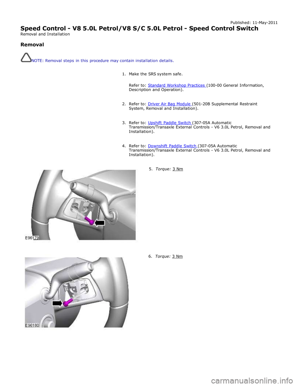
5. Torque: 3 Nm 6. Torque: 3 Nm
Page 1662 of 3039
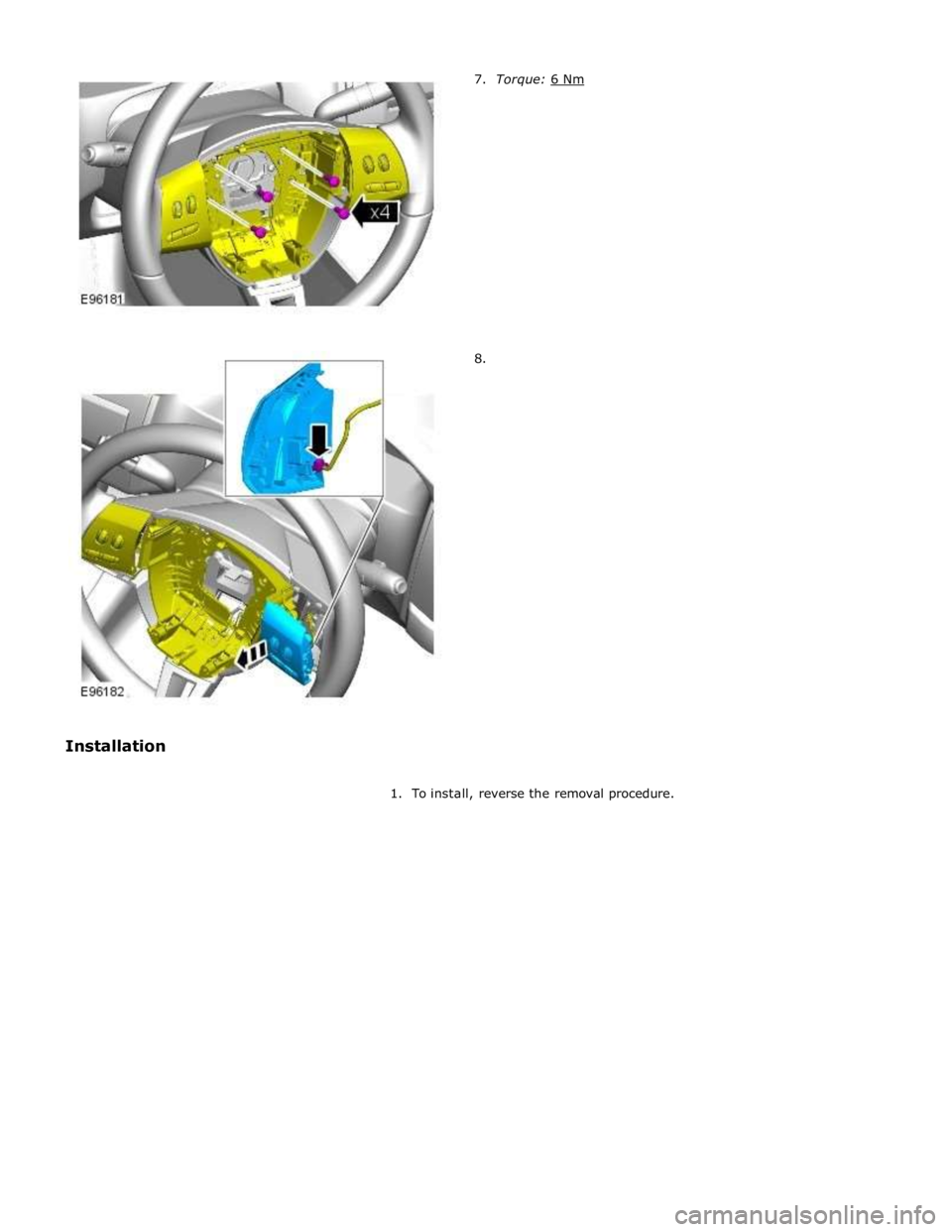
8.
1. To install, reverse the removal procedure.
Page 1663 of 3039
Climate Control System - General Information -
Lubricants, Fluids, Sealers and Adhesives
NOTE: NAS vehicles. Published: 29-Jan-2014
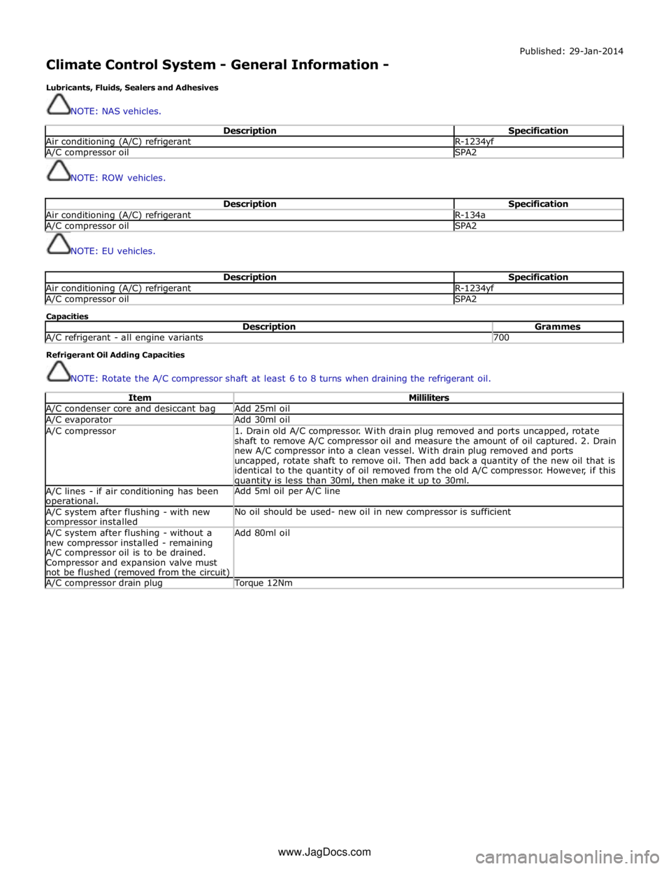
Description Specification Air conditioning (A/C) refrigerant R-1234yf A/C compressor oil SPA2
NOTE: ROW vehicles.
Description Specification Air conditioning (A/C) refrigerant R-134a A/C compressor oil SPA2
NOTE: EU vehicles.
Description Specification Air conditioning (A/C) refrigerant R-1234yf A/C compressor oil SPA2 Capacities
Description Grammes A/C refrigerant - all engine variants 700 Refrigerant Oil Adding Capacities
NOTE: Rotate the A/C compressor shaft at least 6 to 8 turns when draining the refrigerant oil.
Item Milliliters A/C condenser core and desiccant bag Add 25ml oil A/C evaporator Add 30ml oil A/C compressor
1. Drain old A/C compressor. With drain plug removed and ports uncapped, rotate
shaft to remove A/C compressor oil and measure the amount of oil captured. 2. Drain
new A/C compressor into a clean vessel. With drain plug removed and ports
uncapped, rotate shaft to remove oil. Then add back a quantity of the new oil that is
identical to the quantity of oil removed from the old A/C compressor. However, if this quantity is less than 30ml, then make it up to 30ml. A/C lines - if air conditioning has been operational. Add 5ml oil per A/C line A/C system after flushing - with new compressor installed No oil should be used- new oil in new compressor is sufficient A/C system after flushing - without a
new compressor installed - remaining
A/C compressor oil is to be drained.
Compressor and expansion valve must
not be flushed (removed from the circuit) Add 80ml oil A/C compressor drain plug Torque 12Nm www.JagDocs.com
Page 1664 of 3039
Published: 11-Jul-2014
Climate Control System - General Information - Climate Control System
Diagnosis and Testing
Principles of Operation
For a detailed description of the Climate Control System, refer to the relevant Description and Operation sections in the
Workshop Manual. REFER to:
Air Distribution and Filtering (412-01 Climate Control, Description and Operation), Air Distribution and Filtering (412-01 Climate Control, Description and Operation), Air Distribution and Filtering (412-01 Climate Control, Description and Operation), Heating and Ventilation (412-01 Climate Control, Description and Operation), Heating and Ventilation (412-01 Climate Control, Description and Operation), Heating and Ventilation (412-01 Climate Control, Description and Operation), Air Conditioning (412-01 Climate Control, Description and Operation), Air Conditioning (412-01 Climate Control, Description and Operation), Air Conditioning (412-01 Climate Control, Description and Operation), Control Components (412-01 Climate Control, Description and Operation), Control Components (412-01 Climate Control, Description and Operation), Control Components (412-01 Climate Control, Description and Operation), Electric Booster Heater (412-02 Auxiliary Climate Control, Description and Operation), Electric Booster Heater (412-02 Auxiliary Climate Control, Description and Operation), Electric Booster Heater (412-02 Auxiliary Climate Control, Description and Operation).
Inspection and Verification
WARNING: Servicing must be carried out by personnel familiar with both vehicle system and the charging and testing
equipment. All operations must be carried out in a well ventilated area away from open flame and heat sources.
CAUTION: Diagnosis by substitution from a donor vehicle is NOT acceptable. Substitution of control modules does not
guarantee confirmation of a fault, and may also cause additional faults in the vehicle being tested and/or the donor vehicle.
NOTE: Check and rectify basic faults before beginning diagnostic routines involving pinpoint tests.
1. Verify the customer concern
2. Visually inspect for obvious signs of damage and system integrity
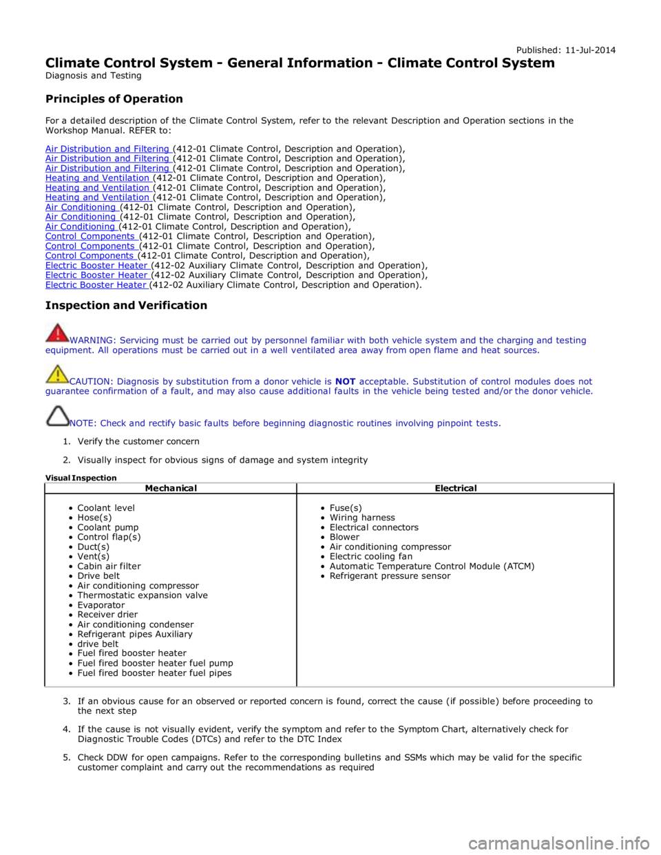
Visual Inspection
Mechanical Electrical
Coolant level
Hose(s)
Coolant pump
Control flap(s)
Duct(s)
Vent(s)
Cabin air filter
Drive belt
Air conditioning compressor
Thermostatic expansion valve
Evaporator
Receiver drier
Air conditioning condenser
Refrigerant pipes Auxiliary
drive belt
Fuel fired booster heater
Fuel fired booster heater fuel pump
Fuel fired booster heater fuel pipes
Fuse(s)
Wiring harness
Electrical connectors
Blower
Air conditioning compressor
Electric cooling fan
Automatic Temperature Control Module (ATCM)
Refrigerant pressure sensor
3. If an obvious cause for an observed or reported concern is found, correct the cause (if possible) before proceeding to
the next step
4. If the cause is not visually evident, verify the symptom and refer to the Symptom Chart, alternatively check for
Diagnostic Trouble Codes (DTCs) and refer to the DTC Index
5. Check DDW for open campaigns. Refer to the corresponding bulletins and SSMs which may be valid for the specific
customer complaint and carry out the recommendations as required
Page 1665 of 3039
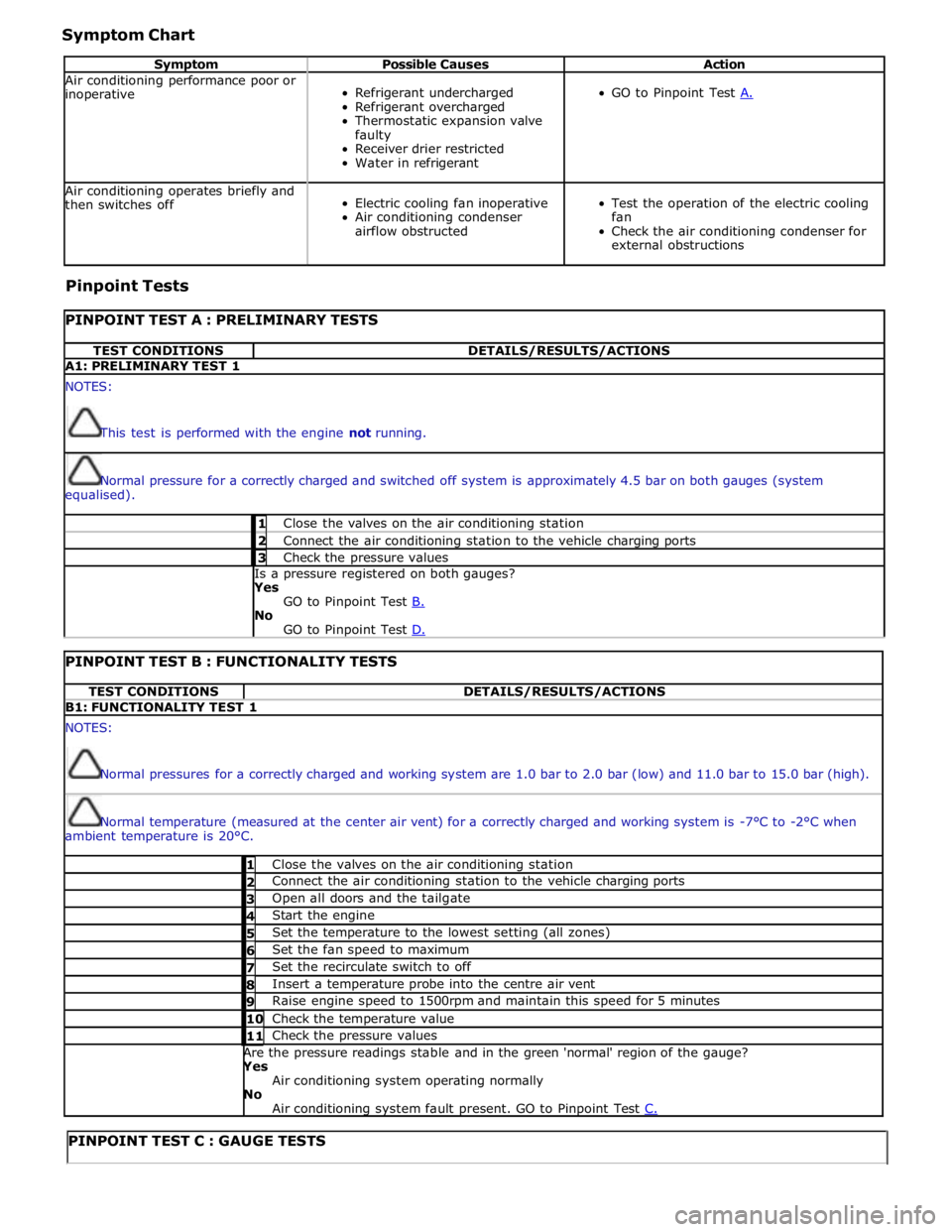
Symptom Chart
Symptom Possible Causes Action Air conditioning performance poor or
inoperative
Refrigerant undercharged
Refrigerant overcharged
Thermostatic expansion valve
faulty
Receiver drier restricted
Water in refrigerant
GO to Pinpoint Test A. Air conditioning operates briefly and
then switches off
Electric cooling fan inoperative
Air conditioning condenser
airflow obstructed
Test the operation of the electric cooling
fan
Check the air conditioning condenser for
external obstructions Pinpoint Tests
PINPOINT TEST A : PRELIMINARY TESTS TEST CONDITIONS DETAILS/RESULTS/ACTIONS A1: PRELIMINARY TEST 1 NOTES:
This test is performed with the engine not running.
Normal pressure for a correctly charged and switched off system is approximately 4.5 bar on both gauges (system
equalised). 1 Close the valves on the air conditioning station 2 Connect the air conditioning station to the vehicle charging ports 3 Check the pressure values Is a pressure registered on both gauges? Yes
GO to Pinpoint Test B. No
GO to Pinpoint Test D.
PINPOINT TEST B : FUNCTIONALITY TESTS TEST CONDITIONS DETAILS/RESULTS/ACTIONS B1: FUNCTIONALITY TEST 1 NOTES:
Normal pressures for a correctly charged and working system are 1.0 bar to 2.0 bar (low) and 11.0 bar to 15.0 bar (high).
Normal temperature (measured at the center air vent) for a correctly charged and working system is -7°C to -2°C when
ambient temperature is 20°C. 1 Close the valves on the air conditioning station 2 Connect the air conditioning station to the vehicle charging ports 3 Open all doors and the tailgate 4 Start the engine 5 Set the temperature to the lowest setting (all zones) 6 Set the fan speed to maximum 7 Set the recirculate switch to off 8 Insert a temperature probe into the centre air vent 9 Raise engine speed to 1500rpm and maintain this speed for 5 minutes 10 Check the temperature value 11 Check the pressure values Are the pressure readings stable and in the green 'normal' region of the gauge? Yes
Air conditioning system operating normally No
Air conditioning system fault present. GO to Pinpoint Test C.
PINPOINT TEST C : GAUGE TESTS
Page 1666 of 3039
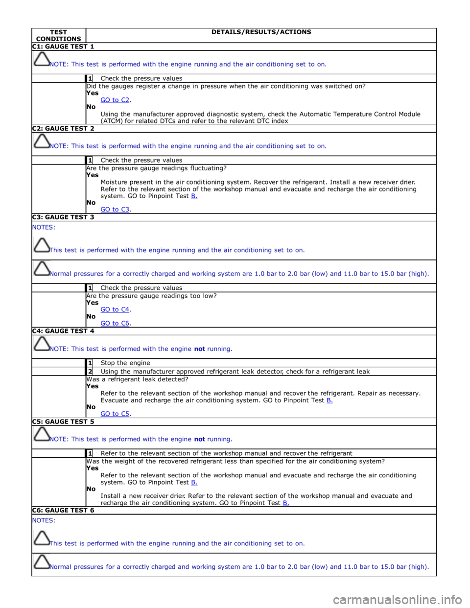
TEST
CONDITIONS DETAILS/RESULTS/ACTIONS C1: GAUGE TEST 1
NOTE: This test is performed with the engine running and the air conditioning set to on. 1 Check the pressure values Did the gauges register a change in pressure when the air conditioning was switched on? Yes
GO to C2. No
Using the manufacturer approved diagnostic system, check the Automatic Temperature Control Module (ATCM) for related DTCs and refer to the relevant DTC index C2: GAUGE TEST 2
NOTE: This test is performed with the engine running and the air conditioning set to on. 1 Check the pressure values Are the pressure gauge readings fluctuating? Yes
Moisture present in the air conditioning system. Recover the refrigerant. Install a new receiver drier.
Refer to the relevant section of the workshop manual and evacuate and recharge the air conditioning
system. GO to Pinpoint Test B. No
GO to C3. C3: GAUGE TEST 3 NOTES:
This test is performed with the engine running and the air conditioning set to on.
Normal pressures for a correctly charged and working system are 1.0 bar to 2.0 bar (low) and 11.0 bar to 15.0 bar (high). 1 Check the pressure values Are the pressure gauge readings too low? Yes
GO to C4. No
GO to C6. C4: GAUGE TEST 4
NOTE: This test is performed with the engine not running. 1 Stop the engine 2 Using the manufacturer approved refrigerant leak detector, check for a refrigerant leak Was a refrigerant leak detected? Yes
Refer to the relevant section of the workshop manual and recover the refrigerant. Repair as necessary.
Evacuate and recharge the air conditioning system. GO to Pinpoint Test B. No
GO to C5. C5: GAUGE TEST 5
NOTE: This test is performed with the engine not running. 1 Refer to the relevant section of the workshop manual and recover the refrigerant Was the weight of the recovered refrigerant less than specified for the air conditioning system? Yes
Refer to the relevant section of the workshop manual and evacuate and recharge the air conditioning
system. GO to Pinpoint Test B. No
Install a new receiver drier. Refer to the relevant section of the workshop manual and evacuate and recharge the air conditioning system. GO to Pinpoint Test B. C6: GAUGE TEST 6 NOTES:
This test is performed with the engine running and the air conditioning set to on.
Normal pressures for a correctly charged and working system are 1.0 bar to 2.0 bar (low) and 11.0 bar to 15.0 bar (high).
Page 1667 of 3039
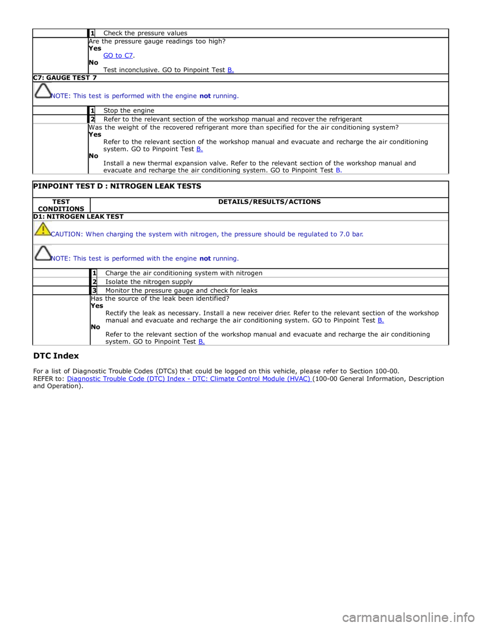
1 Check the pressure values Are the pressure gauge readings too high? Yes
GO to C7. No
Test inconclusive. GO to Pinpoint Test B. C7: GAUGE TEST 7
NOTE: This test is performed with the engine not running. 1 Stop the engine 2 Refer to the relevant section of the workshop manual and recover the refrigerant Was the weight of the recovered refrigerant more than specified for the air conditioning system? Yes
Refer to the relevant section of the workshop manual and evacuate and recharge the air conditioning
system. GO to Pinpoint Test B. No
Install a new thermal expansion valve. Refer to the relevant section of the workshop manual and
evacuate and recharge the air conditioning system. GO to Pinpoint Test B.
PINPOINT TEST D : NITROGEN LEAK TESTS TEST
CONDITIONS DETAILS/RESULTS/ACTIONS D1: NITROGEN LEAK TEST
CAUTION: When charging the system with nitrogen, the pressure should be regulated to 7.0 bar.
NOTE: This test is performed with the engine not running. 1 Charge the air conditioning system with nitrogen 2 Isolate the nitrogen supply 3 Monitor the pressure gauge and check for leaks Has the source of the leak been identified?
Yes
Rectify the leak as necessary. Install a new receiver drier. Refer to the relevant section of the workshop
manual and evacuate and recharge the air conditioning system. GO to Pinpoint Test B. No
Refer to the relevant section of the workshop manual and evacuate and recharge the air conditioning system. GO to Pinpoint Test B.
DTC Index
For a list of Diagnostic Trouble Codes (DTCs) that could be logged on this vehicle, please refer to Section 100-00.
REFER to: Diagnostic Trouble Code (DTC) Index - DTC: Climate Control Module (HVAC) (100-00 General Information, Description and Operation).
Page 1668 of 3039
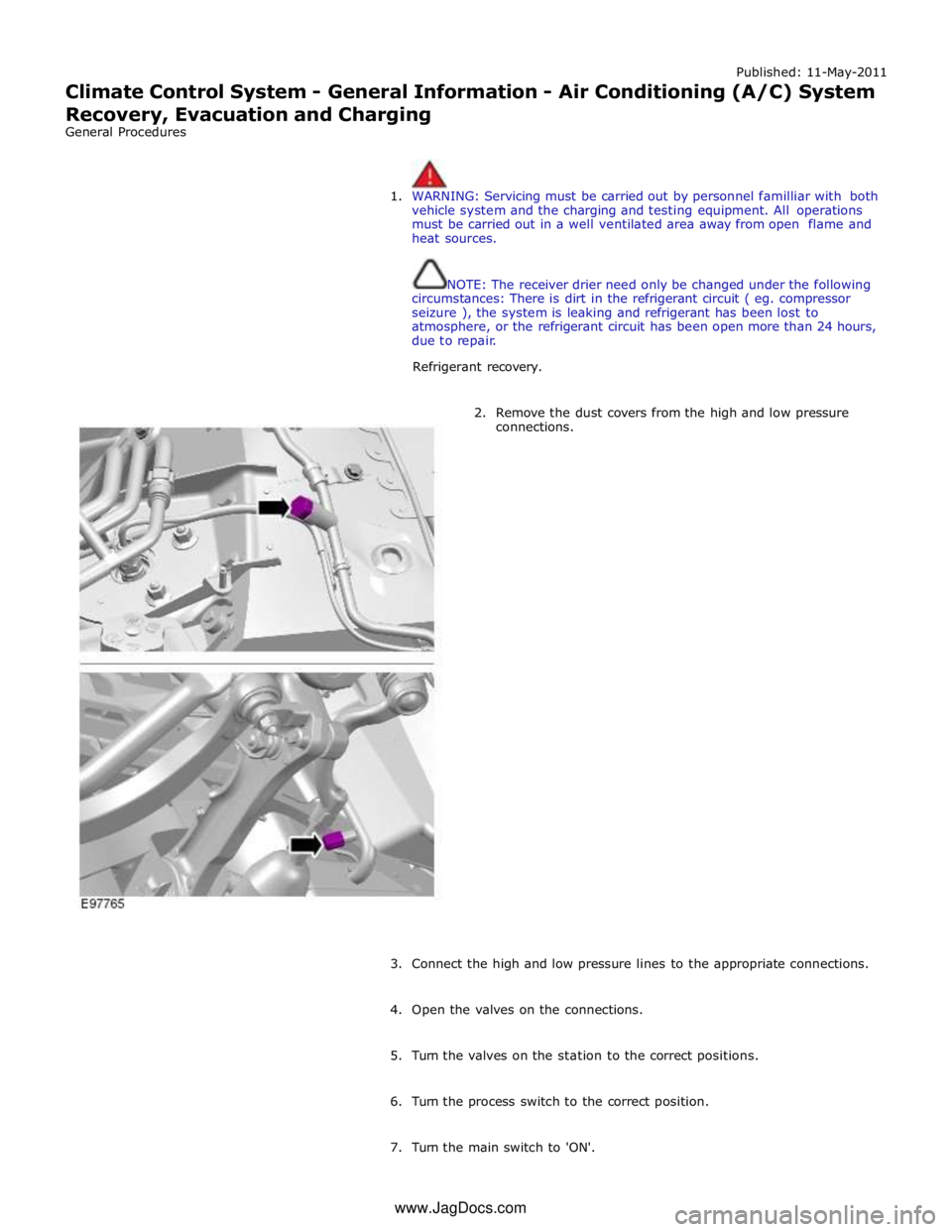
Published: 11-May-2011
Climate Control System - General Information - Air Conditioning (A/C) System
Recovery, Evacuation and Charging
General Procedures
1. WARNING: Servicing must be carried out by personnel familliar with both
vehicle system and the charging and testing equipment. All operations
must be carried out in a well ventilated area away from open flame and
heat sources.
NOTE: The receiver drier need only be changed under the following
circumstances: There is dirt in the refrigerant circuit ( eg. compressor
seizure ), the system is leaking and refrigerant has been lost to
atmosphere, or the refrigerant circuit has been open more than 24 hours,
due to repair.
Refrigerant recovery.
2. Remove the dust covers from the high and low pressure
connections.
3. Connect the high and low pressure lines to the appropriate connections.
4. Open the valves on the connections.
5. Turn the valves on the station to the correct positions.
6. Turn the process switch to the correct position.
7. Turn the main switch to 'ON'. www.JagDocs.com
Page 1669 of 3039

8. WARNING: Refrigerant must always be recycled before re-use to ensure
that the purity of the refrigerantis high enough for safe use in the air
conditioning system. Recycling should always be carried out with
equipment which is design certified by Underwriter Laboratory Inc. for
compliance with SEA J1991. Other equipment may not recycle refrigerant
to the required level of purity. R143a Refrigerant Recover Recycling
Recharging station must not be used with any other type of
refrigerant.Refrigerant R134a from domestic and comercial sources must
not be used in motor vehicles air conditioning systems.
Allow the system to recover the refrigerant from the system.
9. Close the valves on the refrigerant station.
10. Turn the main switch 'OFF'.
11. Close the valves on the connections.
12. Disconnect the high and low pressure connections.
13. Install the dust covers to the connectors.
14. Open the tap at the rear of the station to drain the refrigerant oil.
15. Measure and record the quantity of refrigerant oil recovered from the
system.
16. Close the tap at the rear of the station.
17. Evacuation.
18. Remove the dust covers from the high and low pressure connections.
19. Connect the high and low pressure lines to the appropriate connections.
20. Open the valves on the connections.
21. Turn the valves on the station to the correct positions.
22. Turn the process switch to the correct position.
23. Turn the main switch to 'ON'.
24. Allow the station to evacuate the A/C system.
25. CAUTION: The system must be evacuated immediatley before
recharging commences. Delay between evacuation and recharging is not
permitted
Recharging
26. Close the valves on the refrigerant station.
Page 1670 of 3039

27. Close the valve on the oil charger.
28. Disconnect the yellow line from the refrigerant station.
29. Remove the cover from the oil charger.
30. Pour the correct quantity of refrigerant oil into the oil charger.
31. Install the cover to the oil charger.
32. Connect the yellow line to the refrigerant station.
33. Open the valve on the oil charger.
34. Move the pointer on the refrigerant gauge to mark the position of the
refrigerant drop.
35. Slowly open the correct valve on the refrigerant to allow the vacuum to
pull the refrigerant into the system.
36. Close the valve on the refrigerant station when the correct amount of
refrigerant has been drawn into the air conditioning system.
37. Turn the main switch 'OFF'.
38. Close the valves on the connections.
39. Disconnect the high and low pressure connections.