box JAGUAR XFR 2010 1.G Workshop Manual
[x] Cancel search | Manufacturer: JAGUAR, Model Year: 2010, Model line: XFR, Model: JAGUAR XFR 2010 1.GPages: 3039, PDF Size: 58.49 MB
Page 2537 of 3039
7 Windshield washer pump 8 Wiper/Washer switch - RH (right-hand) steering column multifunction switch 9 Instrument cluster 10 CJB (central junction box) 11 BJB (battery junction box)
WINDSHIELD WIPERS System Operation
Operation of the wipers and washers is controlled by the CJB in response to driver inputs from the wiper control switch and signals from the rain/light sensor. The instrument cluster monitors the condition of the wiper/washer control switch and
transmits driver requests to the CJB over the medium speed CAN bus.
The wiper control switch is connected via hardwired connections to the instrument cluster. The instrument cluster outputs on 4
wires a reference voltage to the wash/wipe switch, the auto wiper switch, the wiper switch and the flick wipe switch. All the
switches are connected to the instrument cluster on a common ground. Each switch function is connected to ground via a
resistor or series of resistors and the instrument cluster monitors the ground signal and determines which function has been
selected. The instrument cluster then outputs the appropriate message on the medium speed CAN bus to the CJB which responds to the requested wiper function. The CJB then activates the appropriate function either directly or via relays in the EJB for the wipers and headlamp powerwashers. Speed Dependent Mode
When the wipers are operating, a vehicle speed signal received by the CJB on the high speed CAN bus is used to operate a speed dependent mode. If the wipers are in fast wipe and the vehicle speed decreases to below 2 km/h (1.2 mph), the wipers
will reduce to the normal wipe speed. When the vehicle speed increases to above 8 km/h (5 mph) the fast wiper speed
selection is restored. If slow speed is selected and the vehicle speed drops below 2km/h (1.2 mph), the wipers will operate in
the intermittent mode. When the vehicle speed increases to above 8 km/h (5 mph) the slow wiper speed selection is restored
– this feature is configurable by the dealer using the approved Jaguar diagnostic system.
Wiper Motor
The wiper motor is controlled by the CJB. The CJB is connected to a wiper motor normal/fast relay in the EJB on 2 wires. The CJB is also connected to a wiper run/park relay, also located in the EJB.
Driver requests are received by the CJB which energizes the wiper motor normal/fast relay in the appropriate mode (normal or fast wipe) and also energizes the run/park relay in the run mode by providing a ground for the relay coils. When wiper
operation is deselected by the driver, the CJB monitors a park switch which is integral with the wiper motor. On receipt of a signal from the park switch, the CJB de-energises the run/park relay, removing the power supply through the normal/fast relay, stopping the wipers in the park position on the windshield.
The wiper motor is a DC (direct current) motor which drives a gear wheel via a worm drive attached to the motor spindle. The
motor has 3 sets of brushes with one brush connected to ground. When the normal/fast relay is energized in the normal
position, a power feed is supplied to the brush directly opposite the ground brush and operates the motor at slow speed.
When the relay is energized in the fast position, a power feed is connected to the second motor brush, which is offset from the
ground brush and operates the motor at the fast speed. With power supplied through the offset brush, the current flows
through fewer motor coil windings. This results in a lower resistance to current flow to the ground brush and produces a higher
motor rotational speed.
WINDSHIELD WASHERS
The windshield washers are controlled by the CJB. A driver request for washer operation, via the wiper control switch, is passed to the instrument cluster on the LIN bus. The instrument cluster passes the message to the CJB on the medium speed CAN bus.
The CJB energizes the windshield washer pump during the up stroke of the first 2 wash/wipe cycles. This ensures that wiper fluid is pushed to the sides of the windshield and eliminates the trail of fluid which can occur if the fluid is pushed to the
bottom of the windshield. The wipers will continue for 3 more cycles, followed after a delay of 4 seconds, by a single dry wipe.
NOTE: The dry wipe feature is configurable using an approved Jaguar diagnostic system.
The operation of the washer pump on the wiper up stroke only is configurable using an approved Jaguar diagnostic system.
The washer button can be pressed and held and the wipers will operate continuously for up to 10 seconds. After this period
when the button is released, the wipers will continue for 3 more cycles, followed after a delay, by a single dry wipe. After this
period washing will be inhibited, the wipers will continue for 3 more cycles, followed after a delay, by a single dry wipe.
Reactivating the switch will recommence the wash/wipe cycle.
RESERVOIR LEVEL SWITCH
The level switch is connected directly to the CJB. The switch is operated by a float which closes contacts within the switch when the fluid level falls to below the switch level. When the contacts are closed a ground path is completed from the CJB through the switch. This is sensed by the CJB which issues a message to the instrument cluster which displays a low fluid level warning.
Page 2559 of 3039

Published: 11-May-2011
Roof Opening Panel - Roof Opening Panel - Component Location
Description and Operation
Component Location
Item Description 1 CJB (central junction box) 2 Roof opening panel, rocker switch 3 Rear window sunblind, switch 4 Roof opening panel, motor 5 Roof opening panel, control module 6 Roof opening panel 7 Rear window sunblind 8 Rear window sunblind, motor assembly 9 Drain tubes (4 off) 10 ABS (anti-lock brake system) module www.JagDocs.com
Page 2561 of 3039

Published: 11-May-2011
Roof Opening Panel - Roof Opening Panel - System Operation and
Component Description
Description and Operation
Control Diagram
NOTE: A = Hardwired
Item Description 1 Battery 2 Megafuse (250 A) 3 Rear window sunblind, switch 4 Rear window sunblind, motor 5 ABS (anti-lock brake system) module 6 Roof opening panel, control module 7 Roof opening panel, rocker switch 8 CJB (central junction box)
Page 2612 of 3039
Published: 26-Jun-2012
Supplemental Restraint System - Air Bag and Safety Belt Pretensioner
Supplemental Restraint System (SRS) - System Operation and Component Description
Description and Operation
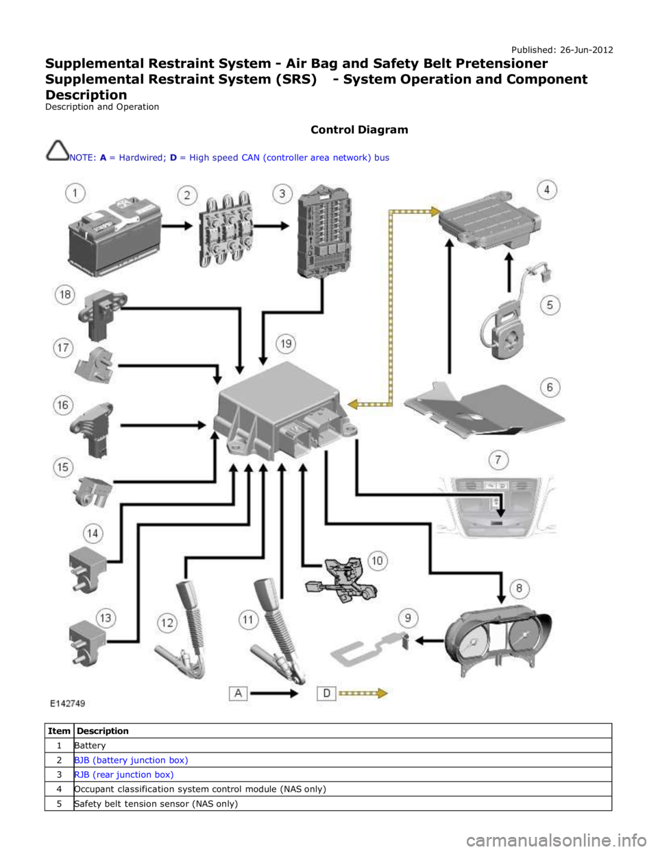
Control Diagram
NOTE: A = Hardwired; D = High speed CAN (controller area network) bus
Item Description 1 Battery 2 BJB (battery junction box) 3 RJB (rear junction box) 4 Occupant classification system control module (NAS only) 5 Safety belt tension sensor (NAS only)
Page 2683 of 3039

Published: 11-May-2011
Pedestrian Protection System - Pedestrian Protection System - System
Operation and Component Description
Description and Operation
Control Diagram
NOTE: A = Hardwired; D = High speed CAN (controller area network) bus; N = Medium speed CAN bus
Item Description 1 Battery 2 CJB (central junction box) 3 Instrument cluster 4 LH (left-hand) hood actuator 5 RH (right-hand) hood actuator 6 Pedestrian protection system control module
Page 2684 of 3039
7 RH accelerometer 8 LH accelerometer 9 RJB (rear junction box) 10 BJB (battery junction box)
System Operation
The pedestrian protection system is operational when the vehicle is traveling at speeds between approximately 20 km/h (12.4
mph) and 45 km/h (28 mph). A vehicle speed signal is received by the pedestrian protection system control module over the
high speed CAN bus.
The system is able to determine if contact is made with a pedestrian or another object, such as a traffic cone, using signals
from accelerometers mounted behind the front bumper. When the system determines contact is made with a pedestrian it fires
the actuators to lift the rear of the hood approximately 130 mm within 35 ms of the 'fire' signal.
When an impact condition is registered, the pedestrian protection system control module outputs an impact signal on the high
speed CAN bus. This signal is used by the RJB to initiate the hazard warning lamps. If this occurs, the hazard warning lamp switch is disabled for the remainder of the current ignition cycle.
If the pedestrian protection system control module detects a fault with the system, it outputs a message on the high speed
CAN bus to the instrument cluster message center. On receipt of this, the message center will display the message 'CHECK PEDESTRIAN SYSTEM'.
The pedestrian protection system control module also stores the VIN (vehicle identification number). If a new control module
is fitted to the vehicle the Jaguar approved diagnostic tool must be used to program the unit with the vehicles VIN.
When the vehicle is delivered from the factory the pedestrian protection system is in a 'safe' plant mode. Normal operating
mode should be activated using the Jaguar approved diagnostic tool during the Pre-Delivery Inspection (PDI) prior to delivery
to the customer. For additional information, refer to the PDI manual.
If any damage is caused to the front of the vehicle, be it cosmetic or structural, repairs must be carried out in line with the
processes contained in the workshop manual. Failure to carry out the correct repair process could compromise operation of the
pedestrian protection system. Refer to GTR for the latest information.
The vehicle must be left for 1 minute after disconnecting the battery before any work can be carried out on the pedestrian
protection system.
Failure Mode Detection
In service, if any fault is detected, or any part of the system is recognized as not being present, the message center displays
the warning 'Check Pedestrian System'.
The bonnet deployment actuators are non-serviceable components, and if they must be replaced due to a fault, or due to
having been deployed, or following any other accident, their barcode labels must be read and recorded in the service database
against the vehicle VIN for security purposes.
After deployment of the pedestrian protection system, the vehicle must be stopped as soon as it is safe to do so. The hazard
warning lamps will be activated and can only be switched off by pressing the engine START/STOP button to turn the engine off
and on again. A warning message 'CHECK PEDESTRIAN SYSTEM' will appear on the message center and the vehicle should be
transported to the nearest dealer/authorised repairer. The vehicle must not be driven when the bonnet has been deployed.
NOTE: If the warning message 'CHECK PEDESTRIAN SYSTEM' appears in the message center when the bonnet has not
been deployed, the vehicle should be taken to the nearest dealer/authorised repairer immediately. It can be driven.
If any significant damage occurs to the front bumper it should be inspected by a dealer/authorised repairer as soon as
possible.
CONTROL MODULE Component Description
The control module is mounted below the hood release lever behind the side trim in the left hand front footwell.
The deployment signal is received from the pedestrian protection system control module. The second-generation system
adopted for XF is all-new to Jaguar and, although similar, differs from that introduced on XK by having an accelerometer-based
sensing system rather than a contact-sensing system. The accelerometer-based system is supplied by Bosch. Mounted very
close to the skin of the bumper, it examines the characteristics of vibration waves caused by impact. Its response time is
quicker, because it does not rely on the front of the bumper being loaded. It uses the 'saved' time to make more complex
decisions, and so has fewer error states. The speed of vehicle and the length of the bonnet define the time available to get
the bonnet into its deployed and stabilized position. It is possible, therefore, to create a time-line counting back from the
predicted moment of head impact to the time when the deployment signals need to be sent. That in turn defines a time from
first contact to decision time.
www.JagDocs.com
Page 2731 of 3039

Seam Sealer
A heat cured, PVC based sealant is applied to specific joint seams during factory assembly. This material is not suitable for
service use and during repair and should be substituted by an approved seam sealer.
NOTE: Where seams are inaccessible following the reassembly or fitting of components, ensure that a paste-type seam
sealer is applied to such seams. Certain seams also become inaccessible after the completion of panel repairs. In such
instances apply seam sealer and paint before final assembly.
Apply seam sealers after the application of primer and before the application of top coat. The sealer must form a continuous
bead, with the profile of the bead dependent on the type of seam. If the seam sealer is applied with a brush take particular
care to maintain the required coverage of the seam.
Ensure that all accessible repair seams are sealed following a repair. Damage to a vehicle often flexes areas of the body
remote from the impact. As a result the seam sealer in these areas may be disturbed by subsequent straightening and repair
operations. Check all seams in the vicinity of the area undergoing repair for evidence of cracked seam sealer, then clean out as
required and apply fresh seam sealer using the following procedure:
Clean the affected seam and re-treat any exposed metal areas with a suitable etch phosphate primer.
Treat affected area with an etch-acid primer.
Apply appropriate seam sealer as necessary.
apply appropriate colour coat (and under body sealer as applicable).
Provided access is adequate, apply seam sealer to both sides of a repair joint. Where access is limited to one side only, (e.g.
box section), treat the affected box member with cavity wax.
Cavity Wax
After repairs, always re-treat these areas with an approved cavity wax. In addition, treat all interior surfaces which have been
disturbed during repairs whether they have been treated in production or not. This includes all box members, cavities and door
interiors.
Before wax injection, ensure that the cavity to be treated is free from any contamination or foreign matter. Where necessary,
clear out any debris.
Ensure that cavity wax is applied after the final paint process and before refitting any trim components.
During application ensure that the wax covers all flanges and seam areas and that it is adequately applied to all repaired
areas of both new and existing panels.
It should be noted that new panel assemblies and complete body shells are supplied without wax injection treatment. Ensure
that such treatment is carried out after repairs.
Effective cavity wax protection is vital. Always observe the following points:
Complete all paint refinish operations before wax application.
Check the spray pattern of injection equipment.
Mask all areas not to be waxed.
Remove body fixings, such as seat belt retractors, if contamination is at all likely.
Move door glasses to fully closed position before treating door interiors.
Treat body areas normally covered by trim before refitting items.
Check that body and door drain holes are clear after the protective wax has dried.
Keep all equipment clean, especially wax injection nozzles.
Page 2766 of 3039

Published: 11-May-2011
Front End Sheet Metal Repairs - Fender Apron Panel Closing Panel
Removal and Installation
Removal
1. NOTE: The fender apron panel closing panel is
manufactured from mild steel.
The fender apron panel closing panel is serviced as a
separate weld-on panel.
2. The fender apron panel closing panel is replaced in conjunction with:
Front bumper cover
Front fender
3. For additional information relating to this repair procedure please see
the following:
For additional information, refer to: Health and Safety Precautions (100-00 General Information, Description and Operation) /
Body Repairs (501-25A Body Repairs - General Information, Description and Operation) /
Corrosion Protection (501-25B Body Repairs - Corrosion Protection, Description and Operation) /
Body and Frame (501-26 Body Repairs - Vehicle Specific Information and Tolerance Checks, Description and Operation).
4. Remove the front fender.
For additional information, refer to: Front Fender (501-27 Front End Sheet Metal Repairs, Removal and Installation).
5. Disconnect the generator electrical connectors.
6. Remove the pedestrian protection hood actuator.
For additional information, refer to: Pedestrian Protection Hood Actuator LH (501-20C Pedestrian Protection System, Removal and Installation) / Pedestrian Protection Hood Actuator RH (501-20C Pedestrian Protection System, Removal and Installation).
7. Remove the secondary bulkhead panel.
For additional information, refer to: Secondary Bulkhead Panel LH - 3.0L NA V6 - AJ27 (501-02 Front End Body Panels, Removal and Installation) / Secondary Bulkhead Panel RH - 3.0L NA V6 - AJ27 (501-02 Front End Body Panels, Removal and Installation).
8. Remove the pedestrian protection actuator bracket.
9. Release and position the fuse box to one side.
10. Release and position the wiring harness to one side.
Page 2798 of 3039

Actuation, Removal and Installation).
12. Remove the left-hand and right-hand front seats.
For additional information, refer to: Front Seat (501-10 Seating, Removal and Installation).
13. Remove the heater core and evaporator core housing.
For additional information, refer to: Heater Core and Evaporator Core Housing (412-01 Climate Control, Removal and Installation).
14. Remove the front safety belt retractor.
For additional information, refer to: Front Safety Belt Retractor (501-20A Safety Belt System, Removal and Installation).
15. Remove the B-pillar side impact sensor.
For additional information, refer to: B-Pillar Side Impact Sensor (501-20B Supplemental Restraint System, Removal and Installation).
16. Remove the left-hand and right-hand front floor covering.
17. Remove the rear floor covering.
18. If the left-hand front side member and suspension top mount assembly
is to be repaired, remove the left-hand rear foot well duct.
19. If the right-hand front side member and suspension top mount assembly
is to be repaired, remove the right-hand rear foot well duct.
20. If the drivers side front side member and suspension top mount is being
repaired, remove the pedal box.
21. Release and position the insulating material at the inner bulkhead to
one side.
22. Release and position the inner bulkhead and floor panel wiring harness
to one side.
23. Drain the fuel tank.
For additional information, refer to: Fuel Tank Draining (310-00 Fuel System - General Information, General Procedures).
24. If the left-hand front side member and suspension top mount assembly
is to be repaired, remove the left-hand under shield.
25. If the right-hand front side member and suspension top mount assembly
is to be repaired, remove the right-hand under shield.
26. If the left-hand front side member and suspension top mount assembly
is to be repaired, remove the fuel supply and return pipes.
27. For diesel engine vehicles only, if the left-hand front side member and
suspension top mount assembly is to be repaired, remove the fuel
cooler.
28. If the right-hand front side member and suspension top mount assembly
is to be repaired, release and position the underfloor wiring harness to
Page 2857 of 3039

Panel Sheet Metal Repairs, Removal and Installation).
7. Remove the side air curtain module.
For additional information, refer to: Side Air Curtain Module (501-20B Supplemental Restraint System, Removal and Installation).
8. Remove the front seat.
For additional information, refer to: Front Seat (501-10 Seating, Removal and Installation).
9. Remove the floor covering.
10. If the passenger side A-pillar reinforcement is to be repaired, remove
the heater core and evaporator core housing.
For additional information, refer to: Heater Core and Evaporator Core Housing (412-01 Climate Control, Removal and Installation).
11. If the right-hand A-pillar reinforcement is to be repaired, remove the
central junction box.
For additional information, refer to: Central Junction Box (CJB) (418-00 Module Communications Network, Removal and Installation).
12. If the drivers side A-pillar reinforcement is to be repaired, remove the
pedal box.
13. Release and lay aside the insulating material at the inner bulkhead.
14. Release and position aside the inner bulkhead and floor panel wiring
harness.
15. NOTE: The NVH components may have already been
removed on the outer panel.
Remove the upper and lower NVH components and if
undamaged retain for reuse.