box JAGUAR XFR 2010 1.G Workshop Manual
[x] Cancel search | Manufacturer: JAGUAR, Model Year: 2010, Model line: XFR, Model: JAGUAR XFR 2010 1.GPages: 3039, PDF Size: 58.49 MB
Page 2133 of 3039

DTC Description Possible Causes Action B1C39-29
Key Lock Switch - Signal
invalid
Key lock switch signal invalid,
stuck/jammed
Switch held for longer than 20
seconds
Key lock switch circuit short to
ground (where connected)
Key lock switch failure
Central Junction Box fault
Refer to the electrical circuit diagrams and
the key lock switch circuit. Clear the DTC
and retest. If no other DTCs are present,
ignore this fault. If the DTC returns, suspect
an internal fault with the Central Junction
Box. Refer to the warranty policy and
procedures manual if a module is suspect B1D06-11
Left Turn Indicator -
Circuit short to ground
Left turn signal short circuit to
ground
Refer to the electrical circuit diagrams and
check left turn signal for short circuit to
ground B1D06-15
Left Turn Indicator -
Circuit short to battery
or open
Left turn signal short circuit to
power
Left turn signal high resistance,
open circuit
Refer to the electrical circuit diagrams and
check left turn signal for short circuit high
resistance, open circuit B1D07-11
Right Turn Indicator -
Circuit short to ground
Right turn signal short circuit to
ground
Refer to the electrical circuit diagrams and
check right turn signal for short circuit to
ground B1D07-15
Right Turn Indicator -
Circuit short to battery
or open
Right turn signal circuit short
circuit to power
Right turn signal circuit high
resistance, open circuit
Refer to the electrical circuit diagrams and
check right turn signal for short circuit high
resistance, open circuit B1D17-11 Battery Backed Sounder
- Circuit short to ground
Battery backed sounder
inclination sensor control circuit
- short to ground
Refer to the electrical circuit diagrams and
check battery backed sounder inclination
sensor control circuit for short to ground B1D18-11
Volumetric Sensor -
Circuit short to ground
Intrusion sensor module supply
circuit - short to ground
Carry out any pinpoint tests associated with
this DTC using the manufacturer approved
diagnostic system. Refer to the electrical
circuit diagrams and check intrusion sensor
module supply circuit for short to ground B1D97-96 Tilt Sensor - Component
internal failure
Component internal failure
Suspect the battery backed sounder, check
and install a new battery backed sounder as
required C1B14-11
Sensor Supply #1 -
Circuit short to ground
Short to ground
Refer to the electrical circuit diagrams and
test window sensor supply circuit for short
to ground C1B14-15
Sensor Supply #1 -
Circuit short to battery
or open
Short to power or open circuit
Refer to the electrical circuit diagrams and
test window sensor supply circuit for short
to power or open circuit C1B15-11 Sensor Supply Voltage A
- Circuit short to ground
Position sensor supply circuit
short to ground
Position sensor fault
Refer to the electrical circuit diagrams and
check the position sensor supply circuit
between the rear door module and the
window motor. If the problem persists,
renew the window motor C1B15-15 Sensor Supply Voltage A
- Circuit short to battery
or open
Position sensor supply circuit
short to power or open circuit
Position sensor fault
Refer to the electrical circuit diagrams and
check the position sensor supply circuit
between the rear door module and the
window motor. If the problem persists,
renew the window motor P1624-13
Anti-Theft System -
Circuit open
RJB anti-theft signal circuit -
open circuit
Refer to the electrical circuit diagrams and
check RJB anti-theft signal circuit for open
circuit
Page 2134 of 3039

DTC Description Possible Causes Action P254F-13
Engine Hood Switch
Circuit/Open - Circuit
open
Hood ajar switch signal circuit -
open circuit
Refer to the electrical circuit diagrams and
check hood ajar switch signal circuit for open
circuit U0010-00
Medium Speed CAN
Communication Bus - No
sub type information
Medium speed CAN
communication Bus
Carry out network integrity test using
manufacturer approved diagnostic system.
Refer to electrical circuit diagrams and test
Medium speed CAN network for open, short
circuit and high resistance U0140-00
Lost Communication
With CJB - No sub type
information
Logged when subscribed CAN
message missing from CJB
Refer to the electrical circuit diagrams and
test power and ground supplies to Central
Junction Box. Check CAN network between
Driver Door Module and Central Junction
Box. Carry out network integrity test using
manufacturer approved diagnostic system U0208-00
Lost Communication
With Driver Seat Module
(DSM) - No sub type
information
Missing message
Refer to the electrical circuit diagrams and
test power and ground supplies to Driver
Seat Module. Check CAN network between
Driver Door Module and Driver Seat Module.
Carry out network integrity test using
manufacturer approved diagnostic system U0300-00
Internal Control Module
Software Incompatibility
- No sub type
information
Car configuration file mismatch
with vehicle specification
NOTE: After updating the car configuration
file, set the ignition to on and wait 30 seconds
before clearing the DTCs
Using the manufacturer approved diagnostic
system, check and up-date the car
configuration file as necessary U2002-24
Switch - Signal stuck
high
Signal stuck high
Clear DTC and re-test. If DTC remains,
install a new passenger side window switch U2004-24
Auxiliary Switch Pack -
Signal stuck high
Signal stuck high
Left or right rear door local
switch pressed for longer than
20 seconds
Switch circuit short to ground or
power
Refer to the electrical circuit diagrams and
check the left and right door switch circuits U2010-11
Switch Illumination -
Circuit short to ground
Switch illumination circuit short
to ground
Refer to electrical circuit diagrams and check
the switch illumination circuit U2012-08
Car Configuration
Parameter(s) - Bus
signal/message failures
Bus signal/message failures
Cycle the ignition status and re-test. If DTC
remains, re-configure the RJB using the
manufacturer approved diagnostic system U2013-24
Switch Pack - Signal
stuck high
Signal stuck high
Clear DTC and re-test. If DTC remains,
install a new driver side window switch pack U2014-44
Control Module
Hardware - Data
memory failure
Data Memory Failure
Install a new DDM/PDM, Refer to the
warranty policy and procedures manual if a
module is suspect U2100-00
Initial Configuration Not
Complete - No sub type
information
Driver/passenger door module is
not configured correctly
Re-configure the DDM/PDM using the
manufacturer approved diagnostic system U2101-00
Control Module
Configuration
Incompatible - No sub
type information
Car configuration file mismatch
with vehicle specification
Re-configure the module using the
manufacturer approved diagnostic system.
Check the configuration of the Car
Configuration File (CCF)
Page 2140 of 3039
Published: 11-May-2011
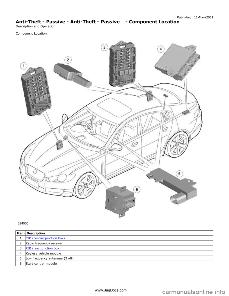
Anti-Theft - Passive - Anti-Theft - Passive - Component Location
Description and Operation
Component Location
Item Description 1 CJB (central junction box) 2 Radio frequency receiver 3 RJB (rear junction box) 4 Keyless vehicle module 5 Low frequency antennae (3 off) 6 Start control module www.JagDocs.com
Page 2142 of 3039
Published: 22-Apr-2013
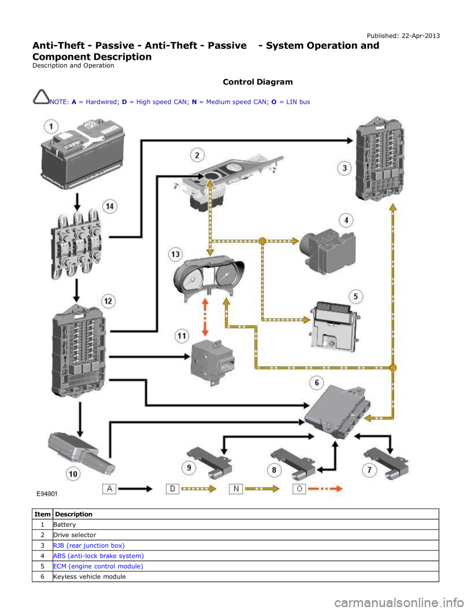
Anti-Theft - Passive - Anti-Theft - Passive - System Operation and
Component Description
Description and Operation
Control Diagram
NOTE: A = Hardwired; D = High speed CAN; N = Medium speed CAN; O = LIN bus
Item Description 1 Battery 2 Drive selector 3 RJB (rear junction box) 4 ABS (anti-lock brake system) 5 ECM (engine control module) 6 Keyless vehicle module
Page 2143 of 3039
7 Low frequency antenna - front 8 Low frequency antenna - center 9 Low frequency antenna - rear 10 Radio frequency receiver 11 Start control module 12 CJB (central junction box) 13 Instrument cluster 14 Megafuse (250 amp)
System Operation
The passive start function prevents the vehicle from being started by unauthorized persons. It does this by immobilizing the
ignition, fuel and engine crank functions. The system is automatic and requires no input from the driver.
At the request of the CJB, the keyless vehicle module prompts each of the Low Frequency (LF) antennae to output a signal. When the Smart Key is in the vehicle cabin, it detects the LF signals and responds with a Radio Frequency (RF)
data-identification signal back to the keyless vehicle module via the RF receiver.
If the data received matches that stored in the keyless vehicle module it continues the passive start process by
communicating a 'Smart Key valid’ signal to the CJB via the medium speed CAN (controller area network) bus.
Once the CJB receives the authorization and confirms a response with an internal calculation, it passes the result to the
instrument cluster on the medium speed CAN bus.
Before the instrument cluster sends a mobilization signal to the ECMit will exchange encrypted data with: The electric steering lock mechanism to authorize unlocking the steering column.
The RJB to authorize fuel pump operation. Once the RJB receives the authorization and confirms the response with an internal calculation, it will enable the FPDM (fuel pump driver module).
The CJB to authorize the ignition status. If the drive selector is in the park position and the driver presses the brake
pedal and simultaneously presses the start/stop switch, the CJB interprets this as an engine crank request. Before the
engine crank request is allowed, the CJB compares a brake pressure signal received from the ABS module. The brake pressure signal is compared to an internally stored threshold value within the CJB. If the signal is greater than the
stored threshold value, a crank request signal is sent to the ECM on the high speed CAN bus.
Once these factors have been confirmed, and the vehicle is in 'Park', the engine can be started by pressing the brake pedal and
the Stop/Start button simultaneously.
NOTES:
If the keyless vehicle module fails to locate the Smart Key, the message 'SMART KEY NOT FOUND PLEASE INSERT IN
SLOT' will appear in the instrument cluster message center. When inserted the start control module will read the transponder
within the Smart Key. If the transponder identification is valid, authorization will be transmitted to the instrument cluster on
the LIN (local interconnect network) bus.
When the vehicle is delivered from the factory the passive start function is inhibited. In this condition the vehicle can
only be started by placing the Smart Key in the start control module. The system should be switched on during the Pre-Delivery
Inspection (PDI) using the Jaguar approved diagnostic system. For additional information, refer to the PDI Manual.
To ensure optimum long term reliability of the smart key the battery must be replaced with a brand new, unused battery. If a
used battery is installed the "SMART KEY BATTERY LOW" message may not be cleared. To avoid contamination of the contacts
the battery should be removed from its packaging and installed into the smart key while wearing gloves. To confirm that the
replacement battery is working correctly press the unlock button twice while holding the smart key outside the vehicle, then
enter the vehicle with the smart key, press the start button and confirm that the "SMART KEY BATTERY LOW" message is not
displayed.
Start Control Module Component Description
The start control module is used if the keyless vehicle module is unable to authorise the Smart Key.
If the keyless vehicle module is unable to identify the Smart Key, for example if the Smart Key battery voltage is low or there
is local RF interference, the transponder within the Smart Key can be read in the conventional manner. The driver will be
alerted to this by a chime and a message in the instrument cluster message center 'SMART KEY NOT FOUND PLEASE INSERT IN
SLOT'.
Once inserted the start control module will read the transponder within the Smart Key. If the transponder identification is
valid, authorization will be transmitted to the instrument cluster on the LIN bus.
NOTE: Inserting the Smart Key into the start control module will not charge the Smart Key battery. The battery is
non-chargeable and must be replaced if defective.
Page 2145 of 3039
Anti-Theft - Passive (Description and Operation), Anti-Theft - Passive (Description and Operation).
Inspection and Verification
Anti-theft - Passive
The best method to confirm the correct operation of the Passive Anti-Theft System (PATS) is to check the LED (located in the
center of the instrument panel). The LED should illuminate solid for 3 seconds, when the ignition status is set to ON, and then
extinguish. This validates all PATS functions (i.e. the key transponder matches a stored key code, the challenge/response
sequence between the respective modules was successful resulting in the EMS being enabled).
Ignition fails to operate
Check that the smart key is located within the vehicle interior, and that it is the correct one for the vehicle.
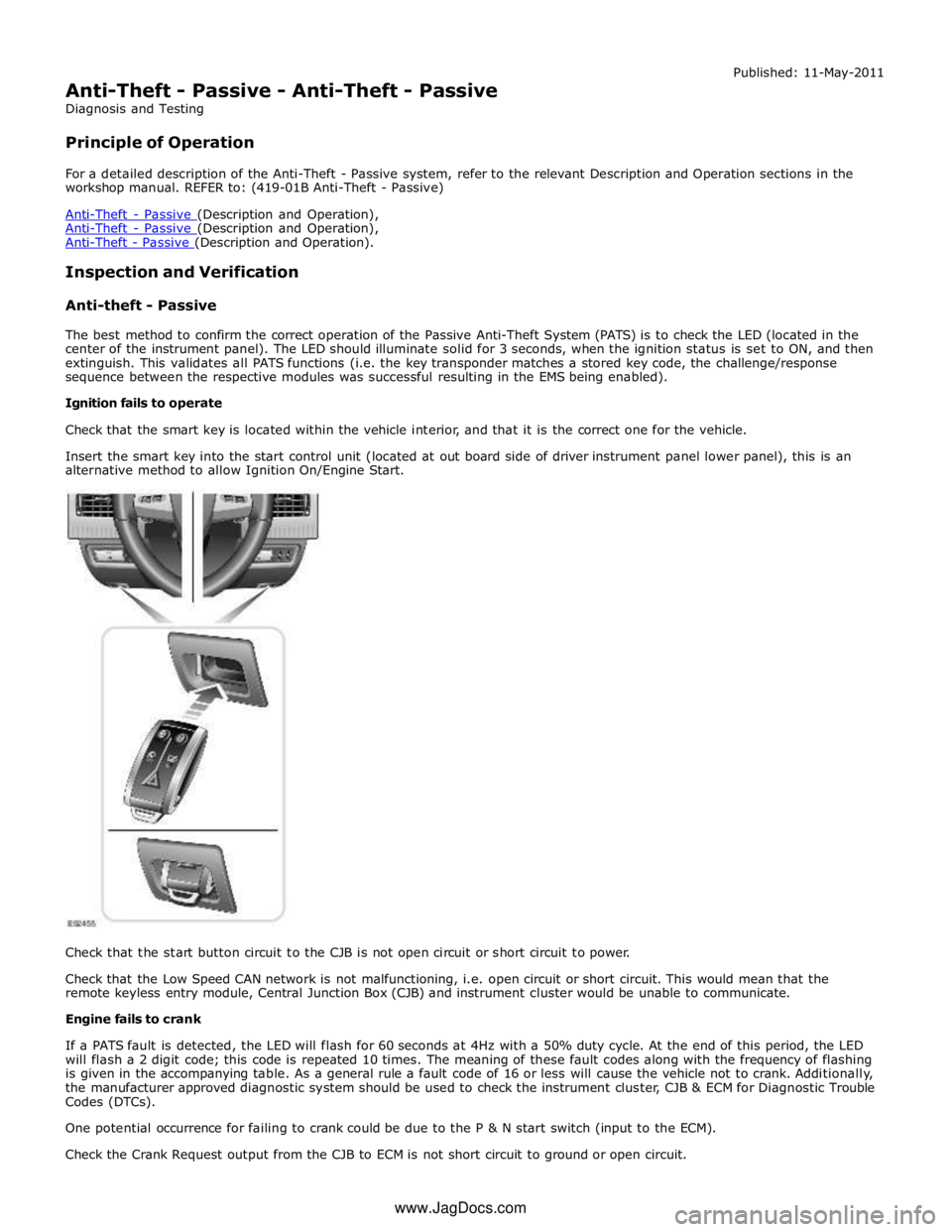
Insert the smart key into the start control unit (located at out board side of driver instrument panel lower panel), this is an
alternative method to allow Ignition On/Engine Start.
Check that the start button circuit to the CJB is not open circuit or short circuit to power.
Check that the Low Speed CAN network is not malfunctioning, i.e. open circuit or short circuit. This would mean that the
remote keyless entry module, Central Junction Box (CJB) and instrument cluster would be unable to communicate.
Engine fails to crank
If a PATS fault is detected, the LED will flash for 60 seconds at 4Hz with a 50% duty cycle. At the end of this period, the LED
will flash a 2 digit code; this code is repeated 10 times. The meaning of these fault codes along with the frequency of flashing
is given in the accompanying table. As a general rule a fault code of 16 or less will cause the vehicle not to crank. Additionally,
the manufacturer approved diagnostic system should be used to check the instrument cluster, CJB & ECM for Diagnostic Trouble
Codes (DTCs).
One potential occurrence for failing to crank could be due to the P & N start switch (input to the ECM).
Check the Crank Request output from the CJB to ECM is not short circuit to ground or open circuit. www.JagDocs.com
Page 2163 of 3039

9 RJB (rear junction box) 10 Battery monitoring system module 11 Rear view camera 12 Driver's side rear door module 13 Driver's door module 14 Driver's seat switches 15 Driver's seat module 16 Start control module 17 Clockspring 18 Battery backed sounder 19 TCM (transmission control module) 20 Generator 21 CJB (central junction box) 22 ECM (engine control module)
Page 2170 of 3039
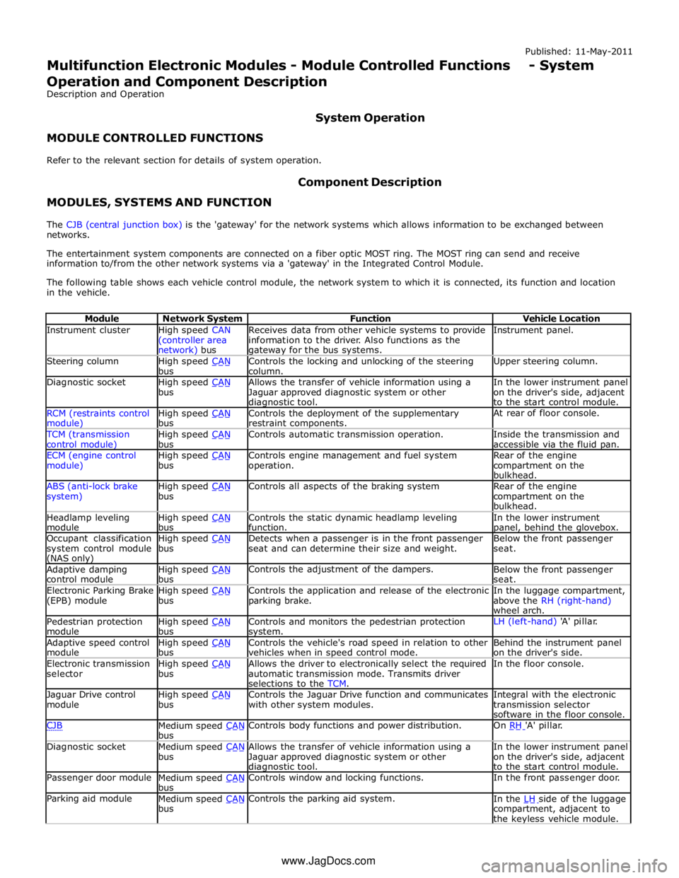
Instrument cluster
High speed CAN
(controller area network) bus Receives data from other vehicle systems to provide
information to the driver. Also functions as the gateway for the bus systems. Instrument panel. Steering column
High speed CAN bus Controls the locking and unlocking of the steering
column. Upper steering column. Diagnostic socket
High speed CAN bus Allows the transfer of vehicle information using a
Jaguar approved diagnostic system or other diagnostic tool. In the lower instrument panel
on the driver's side, adjacent
to the start control module. RCM (restraints control module) High speed CAN bus Controls the deployment of the supplementary
restraint components. At rear of floor console. TCM (transmission
control module) High speed CAN bus Controls automatic transmission operation.
Inside the transmission and
accessible via the fluid pan. ECM (engine control
module) High speed CAN bus Controls engine management and fuel system
operation. Rear of the engine
compartment on the
bulkhead. ABS (anti-lock brake
system) High speed CAN bus Controls all aspects of the braking system
Rear of the engine
compartment on the
bulkhead. Headlamp leveling
module High speed CAN bus Controls the static dynamic headlamp leveling
function. In the lower instrument panel, behind the glovebox. Occupant classification
system control module (NAS only) High speed CAN bus Detects when a passenger is in the front passenger
seat and can determine their size and weight. Below the front passenger
seat. Adaptive damping
control module High speed CAN bus Controls the adjustment of the dampers.
Below the front passenger
seat. Electronic Parking Brake
(EPB) module High speed CAN bus Controls the application and release of the electronic
parking brake. In the luggage compartment,
above the RH (right-hand)
wheel arch. Pedestrian protection
module High speed CAN bus Controls and monitors the pedestrian protection system. LH (left-hand) 'A' pillar. Adaptive speed control
module High speed CAN bus Controls the vehicle's road speed in relation to other
vehicles when in speed control mode. Behind the instrument panel
on the driver's side. Electronic transmission
selector High speed CAN bus Allows the driver to electronically select the required
automatic transmission mode. Transmits driver
selections to the TCM. In the floor console. Jaguar Drive control
module High speed CAN bus Controls the Jaguar Drive function and communicates
with other system modules. Integral with the electronic
transmission selector
software in the floor console. CJB
Medium speed CAN bus Controls body functions and power distribution. On RH 'A' pillar. Diagnostic socket
Medium speed CAN bus Allows the transfer of vehicle information using a
Jaguar approved diagnostic system or other diagnostic tool. In the lower instrument panel
on the driver's side, adjacent
to the start control module. Passenger door module
Medium speed CAN bus Controls window and locking functions. In the front passenger door. Parking aid module
Medium speed CAN bus Controls the parking aid system.
In the LH side of the luggage compartment, adjacent to
the keyless vehicle module. www.JagDocs.com
Page 2171 of 3039
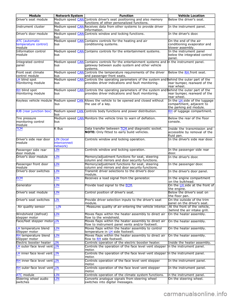
Module Network System Function Vehicle Location
Driver's seat module Medium speed CAN Controls driver's seat positioning and also memory Below the driver's seat. bus functions of other personalized functions.
Instrument cluster Medium speed CAN Receives data from other systems to provide driver In the instrument panel. bus information.
Driver's door module Medium speed CAN Controls window and locking functions. In the driver's door. bus
ATC (automatic Medium speed CAN Contains controls for the heating and air On the end of the air
temperature control)
module bus conditioning systems.
conditioning evaporator and
blower assembly.
Information control Medium speed CAN Contains controls for the entertainment systems. In the instrument panel module bus
below the integrated control
panel.
Integrated control Medium speed CAN Contains controls for the entertainment systems and In the instrument panel. panel bus
gateway between audio system and other vehicle
systems.
Front seat climate Medium speed CAN Controls the temperature requirements of the driver Below the RH front seat. control module bus and passenger front seats.
LH blind spot Medium speed CAN Controls the operating parameters of the system and Behind the outer part of the monitoring module bus provides driver indications and fault monitoring.
rear bumper, rearward of the
rear wheel.
RH blind spot Medium speed CAN Controls the operating parameters of the system and Behind the outer part of the monitoring module bus provides driver indications and fault monitoring.
rear bumper, rearward of the
rear wheel.
Keyless vehicle module Medium speed CAN Allows the vehicle to be opened and closed without In the LH side of the luggage bus the use of a key.
compartment, adjacent to
the parking aid module.
RJB (rear junction box) Medium speed CAN Controls body functions and power distribution. RH of luggage compartment. bus
Tire pressure Medium speed CAN Monitors the vehicle tires to warn of deflation. Below the rear of the floor monitoring control
module bus console.
TCM K Bus Data transfer between TCM and diagnostic socket. NOTE: Only fitted to early build vehicles. Inside the transmission and
accessible by removal of the
fluid pan.
Driver's side rear door
module LIN (local
interconnect
network) Controls window and locking operation. In the driver's side rear door.
Passenger side rear
door module LIN Controls window and locking operation. In the passenger side rear
door.
Driver's door module LIN Memory/adjustment functions for seat, steering
column and mirrors and door security functions. In the driver's door.
Passenger front door
module LIN Memory/adjustment functions for seat, steering
column and mirrors and door security functions. In the passenger door.
Driver's door switches LIN Transmit driver selections to the driver's door
module. In the driver's door panel.
ECM LIN Receives a load signal from the generator. In the engine compartment
on the bulkhead.
Generator LIN Provide load signal to the ECM. On the LH side at the front of the engine.
Driver's seat module LIN Control position of driver's seat. Below the driver's seat on
the floor pan.
Driver's seat switches LIN Provide driver selection inputs to the driver's seat
module. On the outside of the trim
panel on the driver's seat.
Air quality sensor LIN Measures quality of air entering the vehicle interior. At the front of the vehicle,
behind the air intake grill.
Windshield (defrost)
stepper motor LIN Moves flaps within the heater assembly to direct air
flow to the windshield. On the heater assembly.
Face/feet stepper motor LIN Moves flaps within the heater assembly to direct air
flow to instrument panel vents and/or footwell. On the heater assembly.
LH temperature blend
stepper motor
RH temperature blend
stepper motor LIN Moves flaps within the heater assembly to control
temperature in LH side footwell.
LIN Moves flaps within the heater assembly to direct air
flow to RH side footwell. On the heater assembly.
On the heater assembly.
Electric booster heater LIN Controls operation of the electric booster heater. Inside the heater assembly.
LH outer face level vent LIN Controls the operation of the face level vent stepper In the instrument panel.
motor.
LH inner face level vent LIN Controls the operation of the face level vent stepper In the instrument panel.
motor.
RH inner face level vent LIN Controls operation of the face level vent stepper
motor.
RH outer face level vent LIN Controls operation of the face level vent stepper
motor. In the instrument panel.
In the instrument panel.
ATC module LIN Controls operation of the climate system functions. In the instrument panel.
Steering wheel audio
switches LIN Converts analogue signals from steering wheel
switches into digital messages. On the steering wheel.
Page 2293 of 3039

Published: 04-Nov-2013
Rear View Mirrors - Rear View Mirrors - System Operation and Component Description
Description and Operation
Control Diagram
NOTE: A = Hardwired, N = Medium speed CAN (controller area network) bus, O = LIN (local interconnect network) bus
Item Description 1 RJB (rear junction box) 2 RH (right-hand) door module 3 RH door mirror 4 LH (left-hand)side door mirror 5 Interior mirror 6 Battery