box JAGUAR XFR 2010 1.G Workshop Manual
[x] Cancel search | Manufacturer: JAGUAR, Model Year: 2010, Model line: XFR, Model: JAGUAR XFR 2010 1.GPages: 3039, PDF Size: 58.49 MB
Page 2451 of 3039

a power supply to operate the glovebox latch to unlock the glovebox.
The glove box opening is inhibited by the CJB if the anti-theft alarm system is armed and if valet mode is selected using the Touch Screen Display (TSD). The CJB detects the voltage signal from the switch but will not operate the glovebox latch if other condition exists.
GLOVEBOX SWITCH DESCRIPTION Component Description
The conventional glove box switch is located behind the instrument panel veneer. The round button of the switch is visible
through an aperture in the veneer.
Two screws hold the switch in position behind the veneer. The veneer panel has two bosses which the screws are threaded
into.
Page 2488 of 3039

10 Engine-compartment-lid striker 11 Engine-compartment-lid safety hook and guide Central Locking and Keyless Vehicle Locking
Item Description 1 CJB (central junction box) 2 Keyless vehicle, RH front door antenna * – integral to the handle 3 Keyless vehicle, RH rear door antenna * – integral to the handle 4 Central locking radio frequency receiver 5 RJB (rear junction box) 6 Keyless vehicle, luggage compartment antenna * 7 Keyless vehicle module 8 Keyless vehicle, LH rear door antenna * – integral to the handle 9 Keyless vehicle, LH front door antenna * – integral to the handle Comments:
(* Only with passive entry option fitted)
Page 2490 of 3039

Note: A = Hardwired; N = Medium speed CAN (controller area network); O = LIN (local interconnect network) bus 1 Battery 2 Megafuse (250 A) 3 RJB (rear junction box) 4 Door module - front passenger 5 Door ajar switch - front passenger 6 Door latch - front passenger
Page 2491 of 3039

8 Door latch - RH rear passenger 9 Door ajar switch - RH rear passenger 10 Door latch - LH (left-hand) rear passenger 11 Door ajar switch - LH rear passenger 12 Door module - LH rear passenger 13 Door ajar switch - driver door 14 Door latch - driver door 15 Door module - driver door 16 CJB (central junction box) 17 Central-locking radio-frequency receiver 18 Keyless vehicle module Luggage Compartment Lid and Fuel Filler Door Locking
Page 2495 of 3039
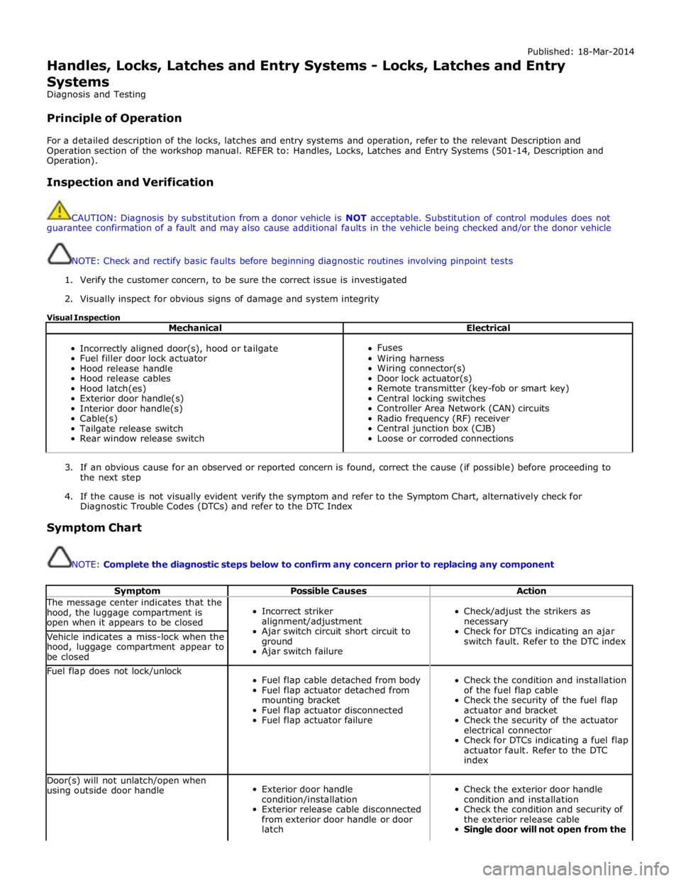
Published: 18-Mar-2014
Handles, Locks, Latches and Entry Systems - Locks, Latches and Entry Systems
Diagnosis and Testing
Principle of Operation
For a detailed description of the locks, latches and entry systems and operation, refer to the relevant Description and
Operation section of the workshop manual. REFER to: Handles, Locks, Latches and Entry Systems (501-14, Description and
Operation).
Inspection and Verification
CAUTION: Diagnosis by substitution from a donor vehicle is NOT acceptable. Substitution of control modules does not
guarantee confirmation of a fault and may also cause additional faults in the vehicle being checked and/or the donor vehicle
NOTE: Check and rectify basic faults before beginning diagnostic routines involving pinpoint tests
1. Verify the customer concern, to be sure the correct issue is investigated
2. Visually inspect for obvious signs of damage and system integrity
Visual Inspection
Mechanical Electrical
Incorrectly aligned door(s), hood or tailgate
Fuel filler door lock actuator
Hood release handle
Hood release cables
Hood latch(es)
Exterior door handle(s)
Interior door handle(s)
Cable(s)
Tailgate release switch
Rear window release switch
Fuses
Wiring harness
Wiring connector(s)
Door lock actuator(s)
Remote transmitter (key-fob or smart key)
Central locking switches
Controller Area Network (CAN) circuits
Radio frequency (RF) receiver
Central junction box (CJB)
Loose or corroded connections
3. If an obvious cause for an observed or reported concern is found, correct the cause (if possible) before proceeding to
the next step
4. If the cause is not visually evident verify the symptom and refer to the Symptom Chart, alternatively check for
Diagnostic Trouble Codes (DTCs) and refer to the DTC Index
Symptom Chart
NOTE: Complete the diagnostic steps below to confirm any concern prior to replacing any component
Symptom Possible Causes Action The message center indicates that the
hood, the luggage compartment is
open when it appears to be closed
Incorrect striker
alignment/adjustment
Ajar switch circuit short circuit to
ground
Ajar switch failure
Check/adjust the strikers as
necessary
Check for DTCs indicating an ajar
switch fault. Refer to the DTC index Vehicle indicates a miss-lock when the
hood, luggage compartment appear to
be closed Fuel flap does not lock/unlock
Fuel flap cable detached from body
Fuel flap actuator detached from
mounting bracket
Fuel flap actuator disconnected
Fuel flap actuator failure
Check the condition and installation
of the fuel flap cable
Check the security of the fuel flap
actuator and bracket
Check the security of the actuator
electrical connector
Check for DTCs indicating a fuel flap
actuator fault. Refer to the DTC
index Door(s) will not unlatch/open when
using outside door handle
Exterior door handle
condition/installation
Exterior release cable disconnected
from exterior door handle or door
latch
Check the exterior door handle
condition and installation
Check the condition and security of
the exterior release cable
Single door will not open from the
Page 2496 of 3039

Symptom Possible Causes Action outside (but opens from the
inside) GO to Pinpoint Test A. Door(s) will not unlatch/open when
using inside door handle
Child lock(s) engaged
Interior door handle
condition/installation
Interior release cable disconnected
from interior door handle or door
latch
Check that the child locks are
disengaged
Check the interior door handle
condition and installation
Check the condition and security of
the interior release cable
Single Door Will Not Open From
The Inside (but opens from the
outside) GO to Pinpoint Test B. Door(s) will not lock/unlock from key
fob, key or internal lock switch
Wiring harness/connectors
Central junction box (CJB)
Door lock switch
Cable fault
Check for relevant stored DTCs
Once any DTC related faults have
been rectified continue with the
diagnostic steps below
No lock / unlock function from
key-fob GO to Pinpoint Test C. Door ajar or miss lock signal at
message centre when door(s) are
closed or alarm triggering
Wiring harness
Instrument cluster
Incorrect striker
alignment/adjustment
Ajar switch circuit short circuit to
ground
Ajar switch failure
Latch Mounted Door Ajar Switch
Test GO to Pinpoint Test D. DTC Index
For a list of Diagnostic Trouble Codes (DTCs) that could be logged on this vehicle, please refer to Section 100-00.
REFER to: Communications Network (418-00, Diagnosis and Testing) /
Locks, Latches and Entry Systems - DTC: With (501-14, Diagnosis and Testing).
Pinpoint Test
PINPOINT TEST A : SINGLE DOOR WILL NOT OPEN FROM THE OUTSIDE (BUT OPENS FROM THE INSIDE) TEST CONDITIONS DETAILS/RESULTS/ACTIONS A1: CHECK THE EXTERIOR DOOR RELEASE CABLE TO EXTERIOR DOOR HANDLE IS INSTALLED CORRECTLY
1 Remove the door trim panel as necessary 2 Confirm the exterior door release cable is correctly installed to the exterior door handle Is the cable correctly installed?
Yes
GO to A2. No
Page 2505 of 3039

Body wiring harness / connectors
Door wiring harness / connectors
Alarm control module
Central junction box (CJB)
Door Latch ajar switch
To investigate the functioning of the door ajar switch contained within the door latch, to prove or eliminate the door
latch mounted door ajar switch as the root cause, follow the process below. This will prevent the unnecessary replacement of
a correctly functioning door latch 1 Remove door trim from door 2 Disconnect door harness from latch for access to connector pins for latch electrical testing 3 Inspect latch module for any visual damage NOTES:
Figure 1 - Unlatched position shown
Figure 2 - First safety latched position shown
Figure 3 - Fully latched position shown
Test will not work if latch is only in first safety latch position 4 Using a small screw driver or similar, rotate latch claw to the second fully latched position (figure 3)
5 Carry out continuity test between terminals 1 and 4 (left side) or 8 and 4 (right side) with claw closed Does the continuity test pass? Yes
The latch ajar switch is working correctly. Do not replace latch.
Investigate for fault elsewhere in vehicle system
Page 2534 of 3039
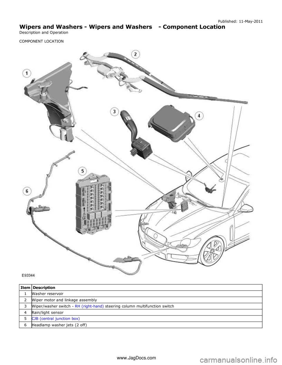
Published: 11-May-2011
Wipers and Washers - Wipers and Washers - Component Location
Description and Operation
COMPONENT LOCATION
Item Description 1 Washer reservoir 2 Wiper motor and linkage assembly 3 Wiper/washer switch - RH (right-hand) steering column multifunction switch 4 Rain/light sensor 5 CJB (central junction box) 6 Headlamp washer jets (2 off) www.JagDocs.com
Page 2535 of 3039
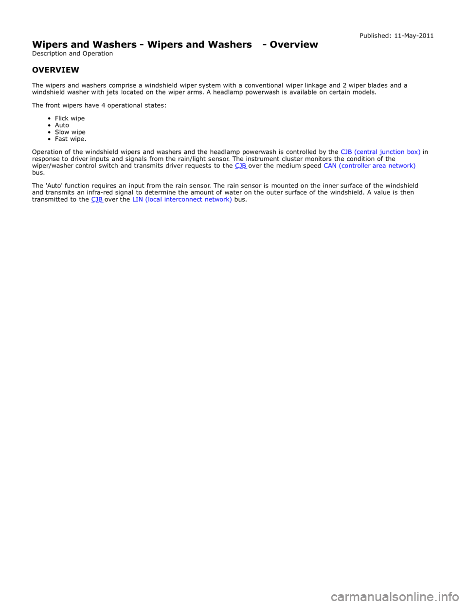
Wipers and Washers - Wipers and Washers - Overview
Description and Operation
OVERVIEW Published: 11-May-2011
The wipers and washers comprise a windshield wiper system with a conventional wiper linkage and 2 wiper blades and a
windshield washer with jets located on the wiper arms. A headlamp powerwash is available on certain models.
The front wipers have 4 operational states:
Flick wipe
Auto
Slow wipe
Fast wipe.
Operation of the windshield wipers and washers and the headlamp powerwash is controlled by the CJB (central junction box) in
response to driver inputs and signals from the rain/light sensor. The instrument cluster monitors the condition of the
wiper/washer control switch and transmits driver requests to the CJB over the medium speed CAN (controller area network) bus.
The 'Auto' function requires an input from the rain sensor. The rain sensor is mounted on the inner surface of the windshield
and transmits an infra-red signal to determine the amount of water on the outer surface of the windshield. A value is then
transmitted to the CJB over the LIN (local interconnect network) bus.
Page 2536 of 3039

Published: 11-May-2011
Wipers and Washers - Wipers and Washers - System Operation and
Component Description
Description and Operation
Control Diagram
NOTE: A = Hardwired; N = Medium speed CAN (controller area network) bus; O = LIN (local interconnect network) bus
Item Description 1 Battery 2 EJB (engine junction box) 3 Wiper motor 4 Headlamp washer pump 5 Rain/Light sensor 6 Washer reservoir fluid level switch