box JAGUAR XFR 2010 1.G Workshop Manual
[x] Cancel search | Manufacturer: JAGUAR, Model Year: 2010, Model line: XFR, Model: JAGUAR XFR 2010 1.GPages: 3039, PDF Size: 58.49 MB
Page 2295 of 3039
On vehicles installed with a driver's power operated memory seat and memory exterior mirrors, a potentiometer is incorporated
within each mirror motor and is used to provide information regarding the actual motor positions. The current position and
memory positions of each door mirror motor are maintained and stored within the corresponding door control module.
The memory exterior mirror positions are also monitored and stored within door control module memory when the reverse gear
mirror dip function is used.
When reverse gear is selected, the door control module stores the current mirror positions and will then dip the passenger
mirror glass to a default dip position. While reverse gear is selected it is possible to store a preferred dipped mirror position by
adjusting the driver/passenger mirror glass to the desired position via the mirror switch pack. When the desired position is
achieved using the switch, the new dip positions will be automatically stored by the door control module when reverse gear is
de-selected. Therefore when reverse gear is re-selected, the dip position recalled by the door control module will be the new
reverse gear mirror dip stored position. When reverse gear is deselected the mirror glass will automatically move to the previous
stored position prior to reverse gear selection.
If the driver selects a memory recall function using the memory seat switch pack, the driver's memory seat and exterior
memory mirrors are moved to a stored memory position.
Exterior mirrors with the power fold/auto fold feature incorporate a motor located in the hinge of each exterior mirror arm.
Operation of the power fold feature is achieved using the exterior mirror switch pack. Operation of the auto fold feature is
achieved using the remote handset.
The power fold function is active when the ignition is in power mode 6 (Ignition).
Both exterior mirrors will power fold when the mirror switch pack 'L' and 'R' switches are pressed together. Pressing the
switches again will unfold the mirrors.
When the instrument cluster is configured for the auto fold feature, the mirrors will fold in when the remote handset lock
button is pressed. The mirrors will unfold when the vehicle is unlocked using the remote handset unlock button.
NOTE: If the mirrors are folded in using the mirror switch pack (power fold) and the vehicle is then locked, subsequent
unlocking of the vehicle will not unfold the mirrors.
When the remote handset unlock button is operated, the CJB recognizes the remote handset for that vehicle and acknowledges the request. The door control modules are connected directly to the AJB (auxiliary junction box) for power supply to the
exterior mirror folding motors.
When the vehicle is locked the door control modules reverse the polarity of the mirror fold motor, power and ground
connections to operate the mirrors in the opposite direction.
Exterior mirror heating is provided with heater elements bonded to the back of the mirror glass. Power supply for the mirror
heating elements is provided by the corresponding driver or passenger door control module via the RJB. The door control modules receive a power supply from the RJB, and are both connected on the medium speed CAN bus to the ATC (automatic temperature control) module. A ground terminal from each door control module completes the circuit. The ATC module automatically controls the mirror heating function whenever the ignition is in power mode 4 (Accessory) and power mode 6
(Ignition).
Operation of the exterior mirror heaters is fully automatic and not controllable by the driver. Exterior mirror heater operation is
determined by ambient air temperature and windshield wiper status. When ambient air temperature reaches a pre-determined
level, the ATC module broadcasts an exterior mirror heating request to the door modules over the medium speed CAN bus. On receipt of this message, the door modules provide feed and ground connections to both exterior mirror heater elements.
The mirror heating is controlled in two phases, the initial heating phase and a second PWM (pulse width modulation) controlled
phase. In the first phase the heater elements in the mirrors are permanently powered for a pre-determined length of time. This
length of time varies with the ambient temperature. During the second PWM phase, the heater elements are turned on and off every 30 seconds. The amount of time the exterior mirror heaters are operational increases if the windshield wipers are
switched on. This ensures the mirrors remain mist free in damp and wet conditions, where there is an increased risk of misting.
Page 2312 of 3039
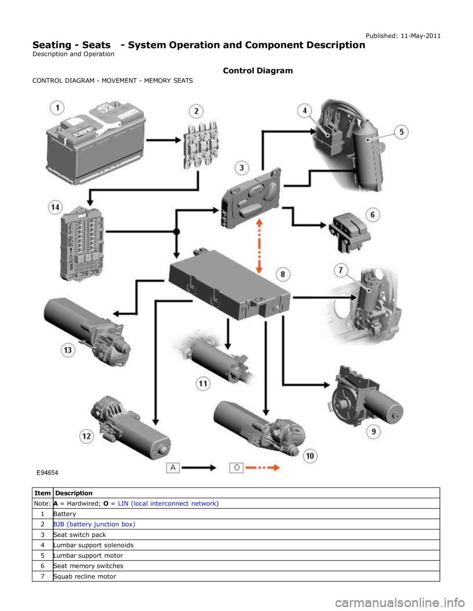
Note: A = Hardwired; O = LIN (local interconnect network) 1 Battery 2 BJB (battery junction box) 3 Seat switch pack 4 Lumbar support solenoids 5 Lumbar support motor 6 Seat memory switches 7 Squab recline motor
Page 2313 of 3039

9 Head restraint motor 10 Cushion tilt motor 11 Cushion extension motor 12 Seat slide motor 13 Seat height motor 14 CJB (central junction box)
Page 2314 of 3039

Note:
A =
Hardwired;
N
=
Medium
speed
CAN
(controller
area
network) bus;
P
=
MOST
ring
1
Battery
2
BJB
3
ATC
(automatic
temperature
control) module
4
RJB
(rear
junction
box)
5
Touch Screen
Display
(TSD)
6
Information
and
Entertainment
module
www.JagDocs.com
Page 2329 of 3039
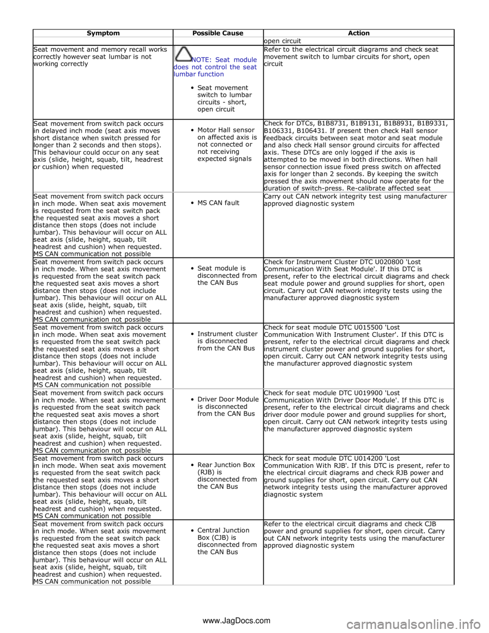
Symptom Possible Cause Action open circuit Seat movement and memory recall works
correctly however seat lumbar is not
working correctly
NOTE: Seat module
does not control the seat
lumbar function
Seat movement
switch to lumbar
circuits - short,
open circuit Refer to the electrical circuit diagrams and check seat
movement switch to lumbar circuits for short, open
circuit Seat movement from switch pack occurs
in delayed inch mode (seat axis moves
short distance when switch pressed for
longer than 2 seconds and then stops). This behaviour could occur on any seat
axis (slide, height, squab, tilt, headrest
or cushion) when requested
Motor Hall sensor
on affected axis is
not connected or
not receiving
expected signals Check for DTCs, B1B8731, B1B9131, B1B8931, B1B9331,
B106331, B106431. If present then check Hall sensor
feedback circuits between seat motor and seat module
and also check Hall sensor ground circuits for affected
axis. These DTCs are only logged if the axis is
attempted to be moved in both directions. When hall
sensor connection issue fixed press switch on affected
axis for longer than 2 seconds. By keeping the switch
pressed the axis movement should now operate for the
duration of switch-press. Re-calibrate affected seat Seat movement from switch pack occurs
in inch mode. When seat axis movement
is requested from the seat switch pack
the requested seat axis moves a short
distance then stops (does not include
lumbar). This behaviour will occur on ALL
seat axis (slide, height, squab, tilt
headrest and cushion) when requested.
MS CAN communication not possible
MS CAN fault Carry out CAN network integrity test using manufacturer
approved diagnostic system Seat movement from switch pack occurs
in inch mode. When seat axis movement
is requested from the seat switch pack
the requested seat axis moves a short
distance then stops (does not include
lumbar). This behaviour will occur on ALL
seat axis (slide, height, squab, tilt
headrest and cushion) when requested.
MS CAN communication not possible
Seat module is
disconnected from
the CAN Bus Check for Instrument Cluster DTC U020800 'Lost
Communication With Seat Module'. If this DTC is
present, refer to the electrical circuit diagrams and check
seat module power and ground supplies for short, open
circuit. Carry out CAN network integrity tests using the
manufacturer approved diagnostic system Seat movement from switch pack occurs
in inch mode. When seat axis movement
is requested from the seat switch pack
the requested seat axis moves a short
distance then stops (does not include
lumbar). This behaviour will occur on ALL
seat axis (slide, height, squab, tilt
headrest and cushion) when requested.
MS CAN communication not possible
Instrument cluster
is disconnected
from the CAN Bus Check for seat module DTC U015500 'Lost
Communication With Instrument Cluster'. If this DTC is
present, refer to the electrical circuit diagrams and check
instrument cluster power and ground supplies for short,
open circuit. Carry out CAN network integrity tests using
the manufacturer approved diagnostic system Seat movement from switch pack occurs
in inch mode. When seat axis movement
is requested from the seat switch pack
the requested seat axis moves a short
distance then stops (does not include
lumbar). This behaviour will occur on ALL
seat axis (slide, height, squab, tilt
headrest and cushion) when requested.
MS CAN communication not possible
Driver Door Module
is disconnected
from the CAN Bus Check for seat module DTC U019900 'Lost
Communication With Driver Door Module'. If this DTC is
present, refer to the electrical circuit diagrams and check
driver door module power and ground supplies for short,
open circuit. Carry out CAN network integrity tests using
the manufacturer approved diagnostic system Seat movement from switch pack occurs
in inch mode. When seat axis movement
is requested from the seat switch pack
the requested seat axis moves a short
distance then stops (does not include
lumbar). This behaviour will occur on ALL
seat axis (slide, height, squab, tilt
headrest and cushion) when requested.
MS CAN communication not possible
Rear Junction Box
(RJB) is
disconnected from
the CAN Bus Check for seat module DTC U014200 'Lost
Communication With RJB'. If this DTC is present, refer to
the electrical circuit diagrams and check RJB power and
ground supplies for short, open circuit. Carry out CAN
network integrity tests using the manufacturer approved
diagnostic system Seat movement from switch pack occurs
in inch mode. When seat axis movement
is requested from the seat switch pack
the requested seat axis moves a short
distance then stops (does not include
lumbar). This behaviour will occur on ALL
seat axis (slide, height, squab, tilt
headrest and cushion) when requested.
MS CAN communication not possible
Central Junction
Box (CJB) is
disconnected from
the CAN Bus Refer to the electrical circuit diagrams and check CJB
power and ground supplies for short, open circuit. Carry
out CAN network integrity tests using the manufacturer
approved diagnostic system www.JagDocs.com
Page 2340 of 3039
Seating - Seats Vehicles With: Climate Controlled Seats
Diagnosis and Testing
Principle of Operation Published: 16-Apr-2014
For a detailed description of the seating systems and operation, refer to the relevant description and operation section of the
workshop manual. REFER to: (501-10 Seating)
Seats (Description and Operation), Seats (Description and Operation), Seats (Description and Operation).
Inspection and Verification
CAUTION: Diagnosis by substitution from a donor vehicle is NOT acceptable. Substitution of control modules does not
guarantee confirmation of a fault and may also cause additional faults in the vehicle being checked and/or the donor vehicle
NOTES:
If the control module or a component is suspect and the vehicle remains under manufacturer warranty, refer to the
warranty policy and procedures manual, or determine if any prior approval programme is in operation, prior to the installation
of a new module/component
Check and rectify basic faults before beginning diagnostic routines involving pinpoint tests
If DTCs are recorded and, after performing the pinpoint tests, a fault is not present, an intermittent concern may be the
cause. Always check for loose connections and corroded terminals
The DTC index containing an actions list is for guidance only any reference to “check and install new blower unit” should
only be carried out following failure confirmation using the pin out diagnostics and/or the over temperature and fluid/air leak
diagnostics contained below. The recording of a DTC does NOT signify a permanently failed unit
The climate system functions in a manner that means any detected error state either intermittent or permanent will shut
down the complete seat climate system until the next ignition cycle, this does not mean that both climate units within the one
seat have failed. This shut down is design intent to protect the system to ensure that the fault detected does not damage the
units, it is possible that both units are functioning correctly and that the fault lies elsewhere within the system. The following
process can be carried out without removing either the seats or the climate units from the vehicle and should correctly identify
any failed units, this should ensure that only failed units are changed under warranty. Any units exhibiting the correct reading
as per process below, should NOT be changed under warranty. If all units have a correct reading then re-confirm customer
symptom, if customer symptom is still present then carry out further system checks
1. Verify the customer concern
2. Visually inspect for obvious signs of mechanical or electrical damage
Visual Inspection
Mechanical Electrical
Seat heater switch condition and installation
Battery condition and state of charge
Fuses
Harnesses and connectors
Seat heater switch(es)
Seat heater elements
Seat module(s)
Ignition switch
Battery junction box
Central junction box
LIN circuit
3. If an obvious cause for an observed or reported concern is found, correct the cause (if possible) before proceeding to
the next step
4. If the cause is not visually evident, carry out normal dealer warranty process, perform on-demand self test, check for
DTCs and refer to the relevant DTC index
5. Allow 30 mins since the last seat/cooled operation prior to carrying out pin testing detailed below in the section
"Connector and Pin Information"
Page 2352 of 3039

DTC Description Possible Causes Action U0010-88
Medium Speed CAN
Communication Bus -
Bus off
Medium speed CAN
communication - Bus off
Refer to the electrical circuit diagrams and check
the power and ground connections to the module
Using the manufacturer approved diagnostic
system, complete a CAN network integrity test
Carry out on demand self test using manufacturer
approved diagnostic system to confirm rectification U0140-00
Lost Communication
With Body Control
Module - No sub type
information
Lost communication with
central junction box
NOTE: This DTC may be stored even though no fault
condition is present and should be ignored unless the
customer has reported a climate seat concern. Clear the
DTC and retest. Verify the customer concern prior to
diagnosis
Refer to the electrical circuit diagrams and check
the power and ground connections to the module
Using the manufacturer approved diagnostic
system, complete a CAN network integrity test
Refer to the electrical circuit diagrams and check
the CAN network between the front seat climate
control module and central junction box
Carry out on demand self test using manufacturer
approved diagnostic system to confirm rectification U0142-00 Lost Communication
Lost communication with
Refer to the electrical circuit diagrams and check With Body Control Module "B" - No sub rear junction box the power and ground connections to the module type information Using the manufacturer approved diagnostic system, complete a CAN network integrity test Refer to the electrical circuit diagrams and check the CAN network between the front seat climate control module and rear junction box Carry out on demand self test using manufacturer approved diagnostic system to confirm rectification U0155-00
Lost Communication
With Instrument Panel
Cluster (IPC) Control
Module - No sub type
information
Lost communication with
instrument cluster
Refer to the electrical circuit diagrams and check
the power and ground connections to the module
Using the manufacturer approved diagnostic
system, complete a CAN network integrity test
Refer to the electrical circuit diagrams and check
the CAN network between the front seat climate
control module and instrument cluster
Carry out on demand self test using manufacturer
approved diagnostic system to confirm rectification U0156-00 Lost Communication
Lost communication with
Refer to the electrical circuit diagrams and check With Information Center "A" - No sub rear seat entertainment the power and ground connections to the module type information control module Using the manufacturer approved diagnostic system, complete a CAN network integrity test Refer to the electrical circuit diagrams and check the CAN network between the front seat climate control module and rear seat entertainment control module Carry out on demand self test using manufacturer approved diagnostic system to confirm rectification U0300-00
Internal Control Module
Software
Incompatibility - No
sub type information
Software stored in front
seat climate control
module is not compatible
with master configuration
Check the front seat climate control module is
configured correctly
Reconfigure the front seat climate control module
using the manufacturer approved diagnostic
system. Clear the DTC and retest the system
Carry out on demand self test using manufacturer
approved diagnostic system to confirm rectification U0401-00
Invalid Data Received
From ECM/PCM - No
sub type information
The engine control module
has transmitted engine
speed quality factor CAN
signal at a specific value
for a greater than expected
time period
Check the engine control module for related DTCs
and refer to the relevant DTC index
On software levels previous to 8X23-14B663-AE
clear the DTC and take no further action if the
system is operating correctly
Page 2353 of 3039
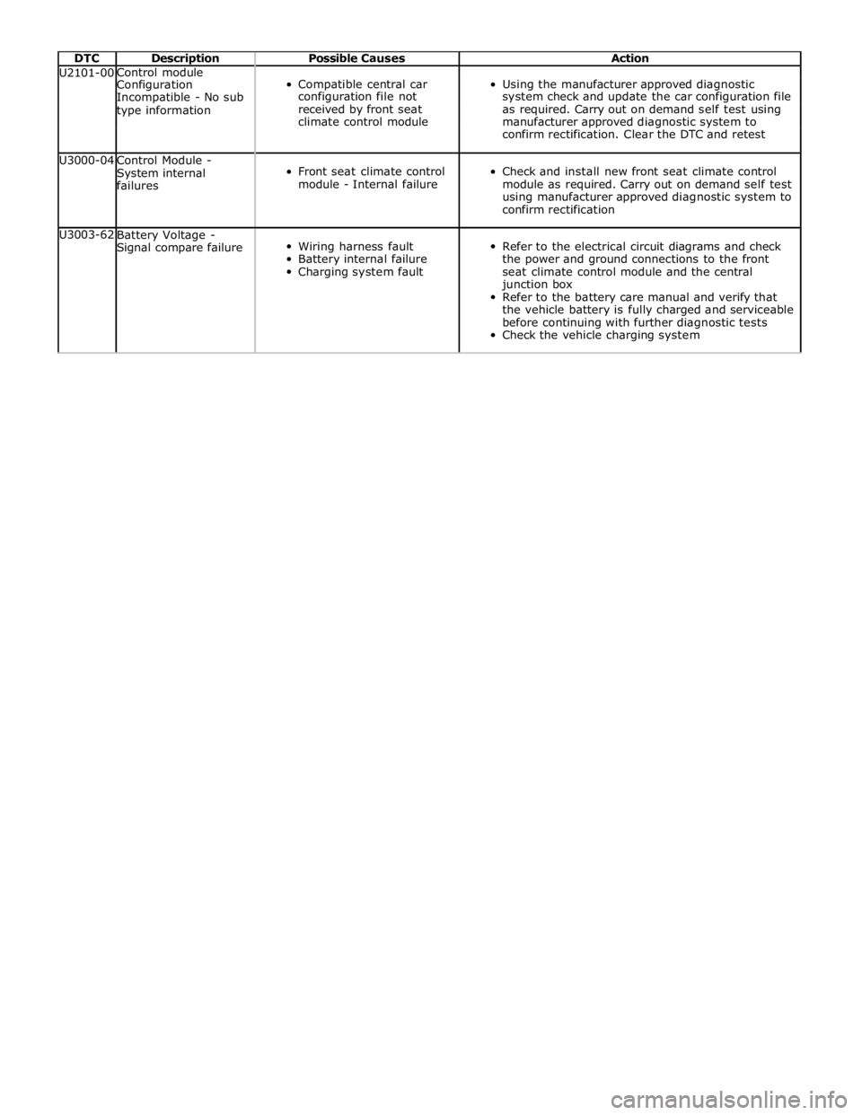
DTC Description Possible Causes Action U2101-00 Control module
Compatible central car
Using the manufacturer approved diagnostic Configuration Incompatible - No sub configuration file not system check and update the car configuration file type information received by front seat as required. Carry out on demand self test using climate control module manufacturer approved diagnostic system to confirm rectification. Clear the DTC and retest U3000-04
Control Module -
System internal
failures
Front seat climate control
module - Internal failure
Check and install new front seat climate control
module as required. Carry out on demand self test
using manufacturer approved diagnostic system to
confirm rectification U3003-62
Battery Voltage -
Signal compare failure
Wiring harness fault
Battery internal failure
Charging system fault
Refer to the electrical circuit diagrams and check
the power and ground connections to the front
seat climate control module and the central
junction box
Refer to the battery care manual and verify that
the vehicle battery is fully charged and serviceable
before continuing with further diagnostic tests
Check the vehicle charging system
Page 2414 of 3039

Published: 24-Jan-2013
Glass, Frames and Mechanisms - Glass, Frames and Mechanisms - System
Operation and Component Description
Description and Operation
Control Diagram
NOTE: A = Hardwired; N = Medium speed CAN; O = LIN bus
Item Description 1 Battery 2 Megafuse (250 amp) 3 CJB (central junction box) 4 RJB (rear junction box) 5 Window control switches - driver's door 6 Door module – driver's door www.JagDocs.com
Page 2449 of 3039
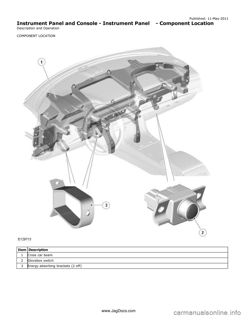
Published: 11-May-2011
Instrument Panel and Console - Instrument Panel - Component Location
Description and Operation
COMPONENT LOCATION
Item Description 1 Cross car beam 2 Glovebox switch 3 Energy absorbing brackets (2 off) www.JagDocs.com