box JAGUAR XFR 2010 1.G Workshop Manual
[x] Cancel search | Manufacturer: JAGUAR, Model Year: 2010, Model line: XFR, Model: JAGUAR XFR 2010 1.GPages: 3039, PDF Size: 58.49 MB
Page 2 of 3039

Table of ContentsContents1: General Information
100: Service Information
100-00: General Information
Description and OperationAbout This Manual
Application and Use of Specifications
Battery and Battery Charging Health and Safety Precautions
Brake System Health and Safety Precautions
Diesel Fuel System Health and Safety Precautions
General Service Information
Health and Safety Precautions
How To Use This Manual
Important Safety Instructions
Petrol and Petrol-Ethanol Fuel Systems Health and Safety Precautions
Solvents, Sealants and Adhesives
Standard Workshop Practices
Symbols Glossary
Supplemental Restraint System (SRS) Health and Safety Precautions
Road/Roller Testing
Window Glass Health and Safety Precautions
Diagnostic Trouble Code (DTC) IndexDTC: Adaptive Damping Module (SUMB)
Diagnostic Trouble Code (DTC) IndexDTC: Anti-Lock Braking System (ABS)
Diagnostic Trouble Code (DTC) IndexDTC: Audio Amplifier Module (AAM)
Diagnostic Trouble Code (DTC) IndexDTC: Blind Spot Monitoring System Module (SODL/SODR)
Diagnostic Trouble Code (DTC) IndexDTC: Central Junction Box (CJB)
Diagnostic Trouble Code (DTC) IndexDTC: Climate Control Module (HVAC)
Diagnostic Trouble Code (DTC) IndexDTC: Digital Audio Broadcast Module (DABM)
Diagnostic Trouble Code (DTC) IndexDTC: Driver Door Module/Passenger Door Module (DDM/PDM)
Diagnostic Trouble Code (DTC) IndexDTC: Driver/Passenger Seat Module (DSM/PSM)
Diagnostic Trouble Code (DTC) IndexDTC: Electric Parking Brake (PBM)
Diagnostic Trouble Code (DTC) Index V8 S/C 5.0L Petrol, DTC: Engine Control Module (ECM)
Diagnostic Trouble Code (DTC) IndexDTC: Front Seat Climate Control Module (DCSM)
Diagnostic Trouble Code (DTC) IndexDTC: Headlamp Control Module (HCM)
Diagnostic Trouble Code (DTC) IndexDTC: Instrument Cluster (IPC)
Diagnostic Trouble Code (DTC) IndexDTC: Integrated Audio Module (IAM)
Diagnostic Trouble Code (DTC) IndexDTC: Integrated Control Panel (FCIMB)
Page 3 of 3039

Diagnostic Trouble Code (DTC) IndexDTC: Occupant Classification System (OCS)
Diagnostic Trouble Code (DTC) IndexDTC: Parking Aid Module (PAM)
Diagnostic Trouble Code (DTC) IndexDTC: Pedestrian Protection System Control Module (PPSCM)
Diagnostic Trouble Code (DTC) IndexDTC: Rear Differential Control Module (RDCM)
Diagnostic Trouble Code (DTC) IndexDTC: Rear Junction Box (RJB)
Diagnostic Trouble Code (DTC) IndexDTC: Remote Keyless Entry Module (RFA)
Diagnostic Trouble Code (DTC) IndexDTC: Restraints Control Module (RCM)
Diagnostic Trouble Code (DTC) IndexDTC: Satellite Digital Audio Radio System Module (SARM)
Diagnostic Trouble Code (DTC) IndexDTC: Speed Control Module (CCM)
Diagnostic Trouble Code (DTC) IndexDTC: Steering Column Lock Module (VIM)
Diagnostic Trouble Code (DTC) IndexDTC: Television Module (TVM)
Diagnostic Trouble Code (DTC) IndexDTC: Tire Pressure Monitoring System Module (TPM)
Diagnostic Trouble Code (DTC) IndexDTC: Touch Screen Display (FCDIM)
Diagnostic Trouble Code (DTC) IndexVehicles With: 6HP28 6-Speed Automatic Transmission, DTC:
Transmission Control Module (TCM)
Diagnostic Trouble Code (DTC) IndexDTC: Transmission Shift Module (GSM)
Diagnostic Trouble Code (DTC) IndexDTC: Portable Audio Interface Control Module (PAICM)
Diagnostic Trouble Code (DTC) IndexDTC: Hybrid Digital Radio Control Module (HDRCM)
Diagnostic Trouble Code (DTC) IndexDTC: Infotainment Control Module (ICM)
Diagnostic Trouble Code (DTC) IndexDTC: Telephone Module (TEL)100-01: Identification Codes
Description and OperationIdentification Codes100-02: Jacking and Lifting
Description and OperationJacking
Lifting100-04: Noise, Vibration and Harshness
Description and OperationNoise, Vibration and Harshness (NVH)Diagnosis and TestingNoise, Vibration and Harshness (NVH)General ProceduresExhaust System Neutralizing2: Chassis
204: Suspension
204-00: Suspension System - General InformationSpecificationDiagnosis and TestingSuspension SystemGeneral ProceduresCamber and Caster Adjustment
Page 23 of 3039

Removal and InstallationApproach Lamp
Headlamp Assembly
Headlamp Leveling Front Sensor
Headlamp Leveling Rear Sensor
High Mounted Stoplamp
Rear Fog Lamp
Rear Lamp Assembly
Side Turn Signal Lamp417-02: Interior Lighting
Description and OperationComponent Location
Overview
System Operation and Component DescriptionDiagnosis and TestingInterior Lighting417-04: Daytime Running Lamps (DRL)
Description and OperationOverview
System Operation and Component Description418: Electrical Distribution
418-00: Module Communications Network
Description and OperationOverview
System Operation and Component DescriptionDiagnosis and TestingCommunications NetworkRemoval and InstallationAuxiliary Junction Box (AJB)
Central Junction Box (CJB)418-02: Wiring Harnesses
Description and OperationWiring HarnessGeneral ProceduresWiring Harness RepairRemoval and InstallationLuggage Compartment Lid Wiring Harness419: Electronic Feature Group
419-01A: Anti-Theft - Active
Description and OperationComponent Location
Overview
Page 52 of 3039

Air Conditioning A/C Accelerator Pedal Position APP
Is a multitrack sensor which inputs the drivers demand into the engine
control module (ECM) After Bottom Dead Center ABDC Event occurring after bottom dead center After Top Dead Center ATDC Event occurring after top dead center Anti-lock Brake System ABS
System which prevents wheel lock-up under braking by sensing lack of
rotation of a wheel(s) and diverting fluid pressure away from it (them) Alternating Current ac Amplitude Modulation AM Automatic Temperature Control ATC Automatic Transmission Fluid ATF Ampere A SI unit of current Ampere hour Ah Barometric Pressure BARO Pressure of surrounding air at any given temperature and altitude Battery positive voltage B+ The positive voltage from a battery or any circuit connected directly to it Before Bottom Dead Center BBDC Event occurring before bottom dead center Before Top Dead Center BTDC Event occurring before top dead center Bottom Dead Center BDC Lowest point of piston travel in a reciprocating engine Battery Junction Box BJB Brake Pedal Position BPP Brake Horsepower BHP
Effective horsepower developed by an engine or motor, as measured by a
brake applied to its output shaft British Standard BS Standard specification issued by the British Standards Institution Brake Traction Control System BTCS
Page 53 of 3039

Bus Topology of a
communication
network Coast Clutch Solenoid CCS Camshaft Position CMP Indicates camshaft position Carbon dioxide CO² Colorless gas with a density of approximately 1.5 times that of air Carbon monoxide CO Poisonous gas produced as the result of incomplete combustion Chlorofluorocarbon CFC Catalytic converter
In-line exhaust system device used to reduce the level of engine exhaust
emissions Celsius C
SI term for the Centigrade scale, with freezing point at zero and boiling point at 100 degrees Compact Disc CD Cylinder Head Temperature
Sensor CHT Sensor A sensor for measuring the temperature of the cylinder head Central Junction Box CJB Crankshaft Position CKP Indicates crankshaft position Clutch Pedal Position CPP Indicates clutch pedal position Controller Area Network CAN
A communication system which allows control modules to be linked together Constant Velocity CV Cubic centimeter cm³ Central Security Module CSM Electronic module to support security system functionality Data Link Connector DLC
Connector providing access and/or control of the vehicle information, operating conditions, and diagnostic information Driver Door Module DDM Electronic module to support driver door functionality Driver Seat Module DSM Electronic module to support driver seat functionality Daytime Running Lamps DRL Deutsche Institut fur Normung DIN German standards regulation body Diagnostic Trouble Code DTC
An alpha/numeric identifier for a fault condition identified by the On-Board Diagnostic (OBD) system Direct current dc
Current which flows in one direction only, though it may have appreciable pulsations in its magnitude Domestic Data Bus D2B Digital Versatile Disc DVD Electronic Automatic Temperature Control EATC
Exhaust Gas Recirculation EGR Exhaust Gas Recirculation Temperature Sensor EGRT Sensing EGR function based on temperature change Electronic Brake Force
Distribution EBD
Engine Control Module ECM Electronic module to support engine functionality Electronic Crash Sensor ECS Sensor to measure severity of impact Engine Coolant Temperature ECT Engine Oil Pressure EOP European On-Board Diagnostic EOBD Electronic Pressure Control EPC Electrically Erasable
Programmable Read-Only Memory EEPROM
Erasable Programmable
Read-Only Memory EPROM
Evaporative Emission EVAP
System designed to prevent fuel vapor from escaping into the atmosphere. Typically includes a charcoal filled canister to absorb fuel vapor Flash Electrically Erasable
Programmable Read-Only Memory FEEPROM
Front Electronic Module FEM Flash Erasable Programmable
Read-Only Memory FEPROM
Frequency Modulation FM Fuel Pump Driver Module FPDM Fuel Rail Pressure FRP Generic Electronic Module GEM Ground GND
Electrical conductor used as a common return for an electrical circuit or
circuits, and with a relative zero potential Global Positioning System GPS Global System for Mobile
Communication GSM
Gross Vehicle Weight GVW Heated Oxygen Sensor HO2S Electrically heated oxygen sensor which induces fuelling corrections
Page 117 of 3039

DTC Description Possible Causes Action Sensor or Left Rear
Vertical Acceleration
Sensor or Right Rear
Vertical Acceleration
Sensor supply partial
short to other circuit
or ground
Left Front Vertical
Acceleration Sensor or
Right Front Vertical
Acceleration Sensor or
Left Rear Vertical
Acceleration Sensor or
Right Rear Vertical
Acceleration Sensor
internal failure
Internal control
module failure U0001-88
High speed CAN
communication
bus - Bus off
Lost Communication
With Engine Control
Module (ECM) (CAN
Bus circuit fault)
Check Engine Control Module for stored DTCs. Refer to the
electrical circuit diagrams and check CAN Bus circuit for faults,
check CAN circuits for open circuits or shorts to power, ground
or other circuits U0100-00
Lost
Communication
With ECM/PCM A
- No sub type
information
Missing message from
ECM
Check Engine Control Module for stored DTCs. Refer to the
electrical circuit diagrams and check CAN Bus for circuit fault U0101-00
Lost
Communication
with TCM - No
sub type
information
Lost Communication
with Transmission
control module (TCM)
(CAN Bus circuit fault)
Check Transmission Control Module for stored DTCs. Refer to
the electrical circuit diagrams and check CAN Bus for circuit
fault U0103-00
Lost
Communication
With Gear Shift
Control Module
A - No sub type
information
Lost Communication
With Gear Shift
Module (GSM) (CAN
Bus circuit fault)
Check Gear Shift Module for stored DTCs. Refer to the
electrical circuit diagrams and check Can Bus for circuit faults U0121-00
Lost
Communication
With Anti-Lock
Brake System
(ABS) Control
Module - No sub type information
Lost Communication
With Anti-Lock Brake
System (ABS) Control
Module (CAN Bus
circuit fault)
Check Anti lock Brake System Control Module for stored DTCs.
Refer to the electrical circuit diagrams and check Can Bus
circuit to Anti lock Brake System Control Module for circuit
faults U0132-00 Lost
Lost Communication
Check Air Suspension Control Module for stored DTCs. Refer to Communication With Suspension With Air Suspension the electrical circuit diagrams and check CAN Bus circuit to Air Control Module Control Module (CAN Suspension Control Module for circuit faults A - No sub type Bus circuit fault information U0136-00
Lost
Communication
With Differential
Control Module -
Rear - No sub type information
Lost Communication
With Rear Differential
Control Module (CAN
Bus circuit fault)
Check Rear Differential Control Module for stored DTCs. Refer
to the electrical circuit diagrams and check Can Bus circuit to
Rear Differential Control Module for circuit faults U0140-00
Lost
Communication
With Body
Control Module -
No sub type
information
Lost Communication
With Body Control
Module (Front Smart
Junction Box) (CAN
Bus circuit fault)
Check Body Control Module for stored DTCs. Refer to the
electrical circuit diagrams and check CAN Bus circuit to Body
Control Module for faults U0142-00
Lost
Communication
With Body
Control Module
B - No sub type
information
Lost Communication
with rear smart
junction box (CAN Bus
circuit fault)
Check Rear Smart Junction Box for stored DTCs. Refer to the
electrical circuit diagrams and check Can Bus circuit to Rear
Smart Junction Box for faults U0155-00
Lost
Communication
With Instrument
Panel Cluster
Lost Communication
With Instrument Panel
Cluster (IPC) Control
Check Instrument Panel Cluster for stored DTCs. Refer to the
electrical circuit diagrams and check CAN Bus to Instrument
Panel Cluster for circuit fault
Page 118 of 3039

DTC Description Possible Causes Action (IPC) Control
Module - No sub
type information Module (CAN bus
circuit fault) U0300-00
Internal control
module software
incompatibility -
No sub type
information
CAN master
configuration ID
incorrect
Check Front Smart Junction Box vehicle configuration file,
check part number of adaptive damping control module U0401-68
Invalid Data
Received from
ECM/PCM A -
Event
information
Invalid Data Received
from Engine Control
Module
Check Engine Control Module for DTCs. Refer to the relevant
DTC index U0402-68
Invalid Data
Received from TCM - Event
information
Invalid Data Received
from Transmission
control module
Check for Transmission Control Module DTCs. Refer to relevant
DTC index U0404-68
Invalid Data
Received from
Gear Shift
Control Module
A - Event
information
Invalid data received
from gear shift control
module
Check Gear Shift Control Module for DTCs. Refer to the
relevant DTC index U0415-68
Invalid Data
Received From
Anti-Lock Brake
System (ABS)
Control Module -
Event
information
Invalid Data Received
From Anti-Lock Brake
System (ABS) Control
Module
Check for Anti lock Brake System DTCs. Refer to the relevant
DTC index U0421-68
Invalid Data
Received from
Suspension
Control Module
A - Event
information
Invalid Data Received
From Air Suspension
Control Module
Check Air Suspension Control Module for stored DTCs. Refer to
the relevant DTC index U0422-68
Invalid Data
Received From
Body Control
Module - Event
information
Invalid Data Received
From Body Control
Module (Front Smart
Junction Box)
Check Body Control Module (Front Smart Junction Box) for
stored DTCs. Refer to the relevant DTC index U0437-68
Invalid Data
Received From
Differential
Control Module -
Rear - Event
information
Invalid Data Received
From Rear Differential
Control Module
Check Rear Differential Control Module for stored DTCs. Refer
to the relevant DTC index U0443-68
Invalid Data
Received From
Body Control
Module B -
Event
information
Invalid Data Received
From body control
module B (Rear Smart
Junction Box)
Check rear smart junction box for DTCs and refer to relevant
DTC index U1A14-00 CAN
initialization
failure - No sub type information
CAN network harness
short, disconnected
Refer to circuit diagrams and check CAN Bus circuit for fault
(short to power, ground or open circuit) U2100-00
Initial
Configuration
Not Complete -
No sub type
information
Car Configuration
Data not loaded (New
Body Control Module
(Front Smart Junction
Box) fitted to vehicle
and not initialized)
Internal Body Control
Module (Front Smart
Junction Box) failure
Install car config to Front Smart Junction Box. Clear DTC and
retest systems U2101-00
Control Module
Configuration
Incompatible -
No sub type
information
Car Configuration
Data transmitted over
CAN does not match
adaptive damping
control module
internal config
Carry out the new module software installation procedure
Page 132 of 3039

DTC Description Possible Causes Action the CAN network U0140-00
Lost Communication
With Body Control
Module - No sub type
information
No sub type information
Refer to the electrical circuit diagrams and check
the power and ground connections to the module.
Using the manufacturer approved diagnostic
system, complete a CAN network integrity test.
Refer to the electrical circuit diagrams and check
the CAN network between the Central Junction
Box and Blind Spot Monitoring System Module U0155-00
Lost Communication
With Instrument Panel
Cluster (IPC) Control
Module - No sub type
information
No sub type information
Refer to the electrical circuit diagrams and check
the power and ground connections to the module.
Using the manufacturer approved diagnostic
system, complete a CAN network integrity test.
Refer to the electrical circuit diagrams and check
the CAN network between the Instrument Cluster
and Blind Spot Monitoring System Module U0232-00
Lost Communication
With Blind Spot
Monitoring System
Module - Left - No sub
type information
CAN bus circuit fault
Harness fault between left
side mirror and left side
module
Refer to the electrical circuit diagrams and check
the power and ground connections to the module.
Using the manufacturer approved diagnostic
system, complete a CAN network integrity test.
Refer to the electrical circuit diagrams and check
the CAN network between the left Blind Spot
Monitoring System Module and the right Blind
Spot Monitoring System Module
Refer to the electrical circuit diagrams and check
the left side harness between the left side mirror
and left hand module U0233-00
Lost Communication
With Blind Spot
Monitoring System
Module - Right - No sub
type information
CAN bus circuit fault
Harness fault between
right side mirror and right
side module
Refer to the electrical circuit diagrams and check
the power and ground connections to the module.
Using the manufacturer approved diagnostic
system, complete a CAN network integrity test.
Refer to the electrical circuit diagrams and check
the CAN network between the left Blind Spot
Monitoring System Module and the right Blind
Spot Monitoring System Module
Refer to the electrical circuit diagrams and check
the right side harness between the right side
mirror and right hand module U0300-00
Internal Control Module
Software Incompatibility
- No sub type
information
No sub type information
Check Central Junction Box for related DTCs and
refer to the relevant DTC Index. Check Restraints
Control Module for related DTCs and refer to DTC
Index. Check correct components are installed
and that the latest software version is installed U0415-68
Invalid Data Received
From Anti-Lock Brake
System (ABS) Control
Module - event
information
Event information
Using the manufacturer approved diagnostic
system check the central junction box and the
anti-lock brake system (ABS) control module for
related DTCs and refer to the relevant DTC Index U0422-68
Invalid Data Received
From Body Control
Module - Event
information
Event information
Check the Central Junction Box for related DTCs
and refer to the relevant DTC index U2100-00
Initial Configuration Not
Complete - No sub type
information
Car Configuration File
information not received
completely
Check/amend Car Configuration File using
manufacturer approved diagnostic system U2101-00
Control Module
Configuration
Incompatible - No sub
type information
Car Configuration File
information incompatible
to Control module
Check/amend Car Configuration File using
manufacturer approved diagnostic system U3000-44
Control Module - Data
memory failure
Control module data
memory failure
Refer to the electrical circuit diagrams and check
the power and ground circuits to the component.
Refer to the warranty policy and procedures
manual if a module is suspect
Page 133 of 3039

DTC Description Possible Causes Action U3000-47
Control Module -
Watchdog/safety
microcontroller failure
Control module internal
watchdog/safety
MicroController failure
Refer to the electrical circuit diagrams and check
the power and ground circuits to the component.
Refer to the warranty policy and procedures
manual if a module is suspect U3000-49
Control Module - Internal
electronic failure
Control module internal
electronic failure (internal
error)
Clear DTC, cycle ignition and retest. If fault
persists, refer to the electrical circuit diagrams
and check the power and ground circuits to the
component. Repair as required, clear DTC and
retest
If fault persists, check and install a new
blindspot monitoring control module as required.
Refer to the warranty policy and procedures
manual if a module is suspect U3003-62
Battery Voltage - Signal
compare failure
Mis-match in battery
voltage, between Central
Junction Box and Blind
Spot Monitoring System
module, of 2 volts or more
Check the module connector for security and
integrity. Refer to the electrical circuit diagrams
and check the Control module supply voltage.
Check vehicle battery voltage and state of
charge. Check the power signal line to the
module
Page 134 of 3039
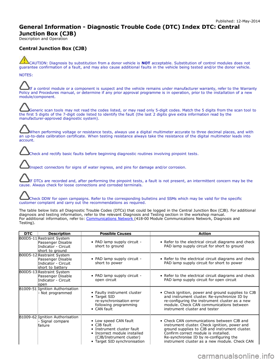
Published: 12-May-2014
General Information - Diagnostic Trouble Code (DTC) Index DTC: Central Junction Box (CJB)
Description and Operation
Central Junction Box (CJB)
CAUTION: Diagnosis by substitution from a donor vehicle is NOT acceptable. Substitution of control modules does not
guarantee confirmation of a fault, and may also cause additional faults in the vehicle being tested and/or the donor vehicle.
NOTES:
If a control module or a component is suspect and the vehicle remains under manufacturer warranty, refer to the Warranty
Policy and Procedures manual, or determine if any prior approval programme is in operation, prior to the installation of a new
module/component.
Generic scan tools may not read the codes listed, or may read only 5-digit codes. Match the 5 digits from the scan tool to
the first 5 digits of the 7-digit code listed to identify the fault (the last 2 digits give extra information read by the
manufacturer-approved diagnostic system).
When performing voltage or resistance tests, always use a digital multimeter accurate to three decimal places, and with
an up-to-date calibration certificate. When testing resistance always take the resistance of the digital multimeter leads into
account.
Check and rectify basic faults before beginning diagnostic routines involving pinpoint tests.
Inspect connectors for signs of water ingress, and pins for damage and/or corrosion.
If DTCs are recorded and, after performing the pinpoint tests, a fault is not present, an intermittent concern may be the
cause. Always check for loose connections and corroded terminals.
Check DDW for open campaigns. Refer to the corresponding bulletins and SSMs which may be valid for the specific
customer complaint and carry out the recommendations as required.
The table below lists all Diagnostic Trouble Codes (DTCs) that could be logged in the Central Junction Box (CJB). For additional
diagnosis and testing information, refer to the relevant Diagnosis and Testing section in the workshop manual.
For additional information, refer to: Communications Network (418-00 Module Communications Network, Diagnosis and Testing).
DTC Description Possible Causes Action B00D5-11
Restraint System
Passenger Disable
Indicator - Circuit
short to ground
PAD lamp supply circuit -
short to ground
Refer to the electrical circuit diagrams and check
PAD lamp supply circuit for short to ground B00D5-12
Restraint System
Passenger Disable
Indicator - Circuit
short to battery
PAD lamp supply circuit -
short to power
Refer to the electrical circuit diagrams and check
PAD lamp supply circuit for short to power B00D5-13
Restraint System
Passenger Disable
Indicator - Circuit open
PAD lamp supply circuit -
open circuit
Refer to the electrical circuit diagrams and check
PAD lamp supply circuit for open circuit B1009-51 Ignition Authorisation
- Not programmed
Faulty instrument cluster
Target SID
re-synchronisation error
following programming
CAN fault
Check ignition, power and ground supplies to CJB
and instrument cluster. Re-synchronize ID by
re-configuring the instrument cluster as a new
module. Check CAN communications between
instrument cluster and tester B1009-62 Ignition Authorisation
- Signal compare
failure
Low speed CAN fault
CJB fault
Instrument cluster fault
Incorrect module installed
(CJB/Instrument cluster)
Target SID synchronisation
Check CAN communications between CJB and
instrument cluster. Check ignition, power and
ground supplies to CJB and instrument cluster.
Confirm correct module is installed.
Re-synchronise ID by re-configuring the
instrument cluster as a new module. Check CAN