box JAGUAR XFR 2010 1.G Workshop Manual
[x] Cancel search | Manufacturer: JAGUAR, Model Year: 2010, Model line: XFR, Model: JAGUAR XFR 2010 1.GPages: 3039, PDF Size: 58.49 MB
Page 2069 of 3039

5 RJB (rear junction box) 6 Battery monitoring system module 7 Rear view camera 8 TCM (transmission control module) 9 Generator 10 Driver's door switch pack 11 Rear door control module 12 Driver's door control module 13 ECM (engine control module) 14 Electronic transmission selector 15 Driver's seat module 16 Driver's seat switch pack 17 Rear door control module 18 Front passenger door control module 19 Clockspring 20 Audio and telephone steering wheel switches 21 Instrument cluster 22 Start control module
Page 2084 of 3039
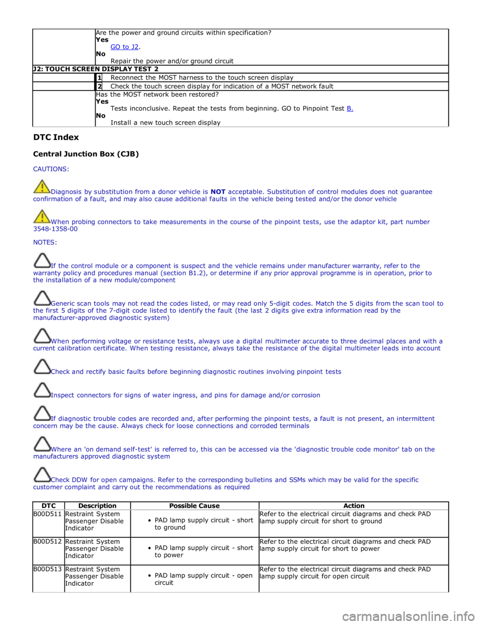
Are the power and ground circuits within specification?
Yes
GO to J2. No
Repair the power and/or ground circuit J2: TOUCH SCREEN DISPLAY TEST 2 1 Reconnect the MOST harness to the touch screen display 2 Check the touch screen display for indication of a MOST network fault Has the MOST network been restored?
Yes
Tests inconclusive. Repeat the tests from beginning. GO to Pinpoint Test B. No
Install a new touch screen display DTC Index
Central Junction Box (CJB)
CAUTIONS:
Diagnosis by substitution from a donor vehicle is NOT acceptable. Substitution of control modules does not guarantee
confirmation of a fault, and may also cause additional faults in the vehicle being tested and/or the donor vehicle
When probing connectors to take measurements in the course of the pinpoint tests, use the adaptor kit, part number
3548-1358-00
NOTES:
If the control module or a component is suspect and the vehicle remains under manufacturer warranty, refer to the
warranty policy and procedures manual (section B1.2), or determine if any prior approval programme is in operation, prior to
the installation of a new module/component
Generic scan tools may not read the codes listed, or may read only 5-digit codes. Match the 5 digits from the scan tool to
the first 5 digits of the 7-digit code listed to identify the fault (the last 2 digits give extra information read by the
manufacturer-approved diagnostic system)
When performing voltage or resistance tests, always use a digital multimeter accurate to three decimal places and with a
current calibration certificate. When testing resistance, always take the resistance of the digital multimeter leads into account
Check and rectify basic faults before beginning diagnostic routines involving pinpoint tests
Inspect connectors for signs of water ingress, and pins for damage and/or corrosion
If diagnostic trouble codes are recorded and, after performing the pinpoint tests, a fault is not present, an intermittent
concern may be the cause. Always check for loose connections and corroded terminals
Where an 'on demand self-test' is referred to, this can be accessed via the 'diagnostic trouble code monitor' tab on the
manufacturers approved diagnostic system
Check DDW for open campaigns. Refer to the corresponding bulletins and SSMs which may be valid for the specific
customer complaint and carry out the recommendations as required
DTC Description Possible Cause Action B00D511
Restraint System
Passenger Disable
Indicator
PAD lamp supply circuit - short
to ground Refer to the electrical circuit diagrams and check PAD
lamp supply circuit for short to ground B00D512
Restraint System
Passenger Disable
Indicator
PAD lamp supply circuit - short
to power Refer to the electrical circuit diagrams and check PAD
lamp supply circuit for short to power B00D513
Restraint System
Passenger Disable
Indicator
PAD lamp supply circuit - open
circuit Refer to the electrical circuit diagrams and check PAD
lamp supply circuit for open circuit
Page 2087 of 3039

DTC Description Possible Cause Action B10F211 Sunroof Control
Sunroof enable signal circuit -
short to ground Carry out any pinpoint tests associated with this DTC
using the manufacturer approved diagnostic system.
Refer to the electrical circuit diagrams and check sunroof
enable signal circuit for short to ground B10F212 Sunroof Control
Sunroof enable signal circuit -
short to power Refer to the electrical circuit diagrams and check sunroof
enable signal circuit for short to power B10F213 Sunroof Control
Sunroof enable signal circuit -
open circuit Refer to the electrical circuit diagrams and check sunroof
enable signal circuit for open circuit B10F311
Left Front Position
Light
Left front side lamps circuit -
short to ground Carry out any pinpoint tests associated with this DTC
using the manufacturer approved diagnostic system.
Refer to the electrical circuit diagrams and check left
front side lamps circuit for short to ground B10F315
Left Front Position
Light
Left front side lamps circuit -
short to power, open circuit Carry out any pinpoint tests associated with this DTC
using the manufacturer approved diagnostic system.
Refer to the electrical circuit diagrams and check left
front side lamps circuit for short to power, open circuit B10F411
Right Front Position
Light
Right front side lamps circuit -
short to ground Carry out any pinpoint tests associated with this DTC
using the manufacturer approved diagnostic system.
Refer to the electrical circuit diagrams and check right
front side lamps circuit for short to ground B10F415
Right Front Position
Light
Right front side lamps circuit -
short to power, open circuit Carry out any pinpoint tests associated with this DTC
using the manufacturer approved diagnostic system.
Refer to the electrical circuit diagrams and check right
front side lamps circuit for short to power, open circuit B10F812
Accessory socket 'A'
relay
Accessory socket 'A' relay
control circuit - short to power Carry out any pinpoint tests associated with this DTC
using the manufacturer approved diagnostic system.
Refer to the electrical circuit diagrams and check
accessory socket 'A' relay control circuit for short to power B10F814
Accessory socket 'A'
relay
Accessory socket 'A' relay
control circuit - short to ground,
open circuit Refer to the electrical circuit diagrams and check
accessory socket 'A' relay control circuit for short to
ground, open circuit B10F912
Accessory socket 'B'
relay
Front powerpoint, trailer tow
connector, road pricing
connector, sunblind power
supply circuits - short to power Refer to the electrical circuit diagrams and check front
powerpoint, trailer tow connector, road pricing connector,
sunblind power supply circuits for short to power B10F914
Accessory socket 'B'
relay
Front powerpoint, trailer tow
connector, road pricing
connector, sunblind power
supply circuits - short to
ground, open circuit Refer to the electrical circuit diagrams and check front
powerpoint, trailer tow connector, road pricing connector,
sunblind power supply circuits for short to ground, open
circuit B10F993
Accessory socket 'B'
relay
Front powerpoint, trailer tow
connector, road pricing
connector, sunblind power
supply circuits - short to power,
ground, open circuit Carry out any pinpoint tests associated with this DTC
using the manufacturer approved diagnostic system.
Refer to the electrical circuit diagrams and check front
powerpoint, trailer tow connector, road pricing connector,
sunblind power supply circuits for short to power, ground,
open circuit B10FA93
Delayed Power Off
relay
ADRC ECM, roof header console
lamp, glove box lamp , RH/LH
footwell lamps, JAG Sense
glove box module, RH/LH
sunvisor lamps, rear dome
lamps switched power circuits -
short to power, open circuit Carry out any pinpoint tests associated with this DTC
using the manufacturer approved diagnostic system.
Refer to the electrical circuit diagrams and check ADRC
ECM, roof header console lamp, glove box lamp , RH/LH
footwell lamps, JAG Sense glove box module, RH/LH
sunvisor lamps, rear dome lamps switched power circuits
for short to power, open circuit B10FF11 Ignition control
ECM and FPDB ignition control
circuit - short to ground Carry out any pinpoint tests associated with this DTC
using the manufacturer approved diagnostic system.
Refer to the electrical circuit diagrams and check ECM and
FPDB ignition control circuit for short to ground B10FF13 Ignition control
ECM and FPDB ignition control
circuit - open circuit Carry out any pinpoint tests associated with this DTC
using the manufacturer approved diagnostic system.
Refer to the electrical circuit diagrams and check ECM and
FPDB ignition control circuit for open circuit
Page 2088 of 3039

DTC Description Possible Cause Action B110011
O2 sensor heater
relay
FPDB O2 sensor heater relay
control circuit - short to ground Carry out any pinpoint tests associated with this DTC
using the manufacturer approved diagnostic system.
Refer to the electrical circuit diagrams and check FPDB O2
sensor heater relay control circuit for short to ground B113D12
Sunroof Global
Open/Close Control
Roof opening panel global
open/close control circuit -
short to power Carry out any pinpoint tests associated with this DTC
using the manufacturer approved diagnostic system.
Refer to the electrical circuit diagrams and check roof
opening panel global open/close control circuit for short
to power B113D14
Sunroof Global
Open/Close Control
Roof opening panel global
open/close control circuit -
short to ground, open circuit Refer to the electrical circuit diagrams and check roof
opening panel global open/close control circuit for short
to ground, open circuit B114011
Engine Crank
Authorisation
Engine crank authorisation
signal circuit - short to ground Carry out any pinpoint tests associated with this DTC
using the manufacturer approved diagnostic system.
Refer to the electrical circuit diagrams and check engine
crank authorisation signal circuit for short to ground B114211 Ignition Status 1
Ignition supply 1 circuits -
short to ground Carry out any pinpoint tests associated with this DTC
using the manufacturer approved diagnostic system.
Refer to the electrical circuit diagrams and check all ignition supply 1 circuits for short to ground B114311 Ignition Status 2
Ignition supply 2 circuits -
short to ground Carry out any pinpoint tests associated with this DTC
using the manufacturer approved diagnostic system.
Refer to the electrical circuit diagrams and check all ignition supply 2 circuits for short to ground B114411
Heated Steering
Wheel Supply
Heated steering wheel supply
circuit - short to ground Carry out any pinpoint tests associated with this DTC
using the manufacturer approved diagnostic system.
Refer to the electrical circuit diagrams and check heated steering wheel supply circuit for short to ground B114511
Glovebox Locking
Motor
Glovebox latch locking motor
circuit - short to ground Carry out any pinpoint tests associated with this DTC
using the manufacturer approved diagnostic system.
Refer to the electrical circuit diagrams and check glovebox latch locking motor circuit for short to ground B114512
Glovebox Locking
Motor
Glovebox latch locking motor
control circuit - short to power Refer to the electrical circuit diagrams and check
glovebox latch locking motor control circuit for short to
power B114513
Glovebox Locking
Motor
Glovebox latch locking motor
control circuit - open circuit Refer to the electrical circuit diagrams and check
glovebox latch locking motor control circuit for open
circuit B114612
Passive sounder
Supply
Security passive sounder
control circuit - short to power Refer to the electrical circuit diagrams and check security
passive sounder control circuit for short to power B114614
Passive sounder
Supply
Security passive sounder
control circuit - short to ground,
open circuit Refer to the electrical circuit diagrams and check security
passive sounder control circuit for short to ground, open
circuit B115811
Front Passenger
Seat Heater Sensor
Front passenger seat heater
sensor circuit - short to ground Carry out any pinpoint tests associated with this DTC
using the manufacturer approved diagnostic system.
Refer to the electrical circuit diagrams and check front passenger seat heater sensor circuit for short to ground B115813
Front Passenger
Seat Heater Sensor
Front passenger seat heater
sensor circuit - open circuit Carry out any pinpoint tests associated with this DTC
using the manufacturer approved diagnostic system.
Refer to the electrical circuit diagrams and check front passenger seat heater sensor circuit for open circuit B115911
Driver Seat Heater
Sensor
Driver seat heater sensor
circuit - short to ground Carry out any pinpoint tests associated with this DTC
using the manufacturer approved diagnostic system.
Refer to the electrical circuit diagrams and check driver
seat heater sensor circuit for short to ground B115913
Driver Seat Heater
Sensor
Driver seat heater sensor
circuit - open circuit Carry out any pinpoint tests associated with this DTC
using the manufacturer approved diagnostic system.
Refer to the electrical circuit diagrams and check driver
seat heater sensor circuit for open circuit B115A11
Front Passenger
Seat Heater
Front passenger seat heater
supply circuit - short to ground Carry out any pinpoint tests associated with this DTC
using the manufacturer approved diagnostic system.
Refer to the electrical circuit diagrams and check front passenger seat heater supply circuit for short to ground B115A15
Front Passenger
Seat Heater
Front passenger seat heater
supply circuit - short to power,
open circuit Carry out any pinpoint tests associated with this DTC
using the manufacturer approved diagnostic system.
Refer to the electrical circuit diagrams and check front
passenger seat heater supply circuit for short to power, open circuit
Page 2092 of 3039
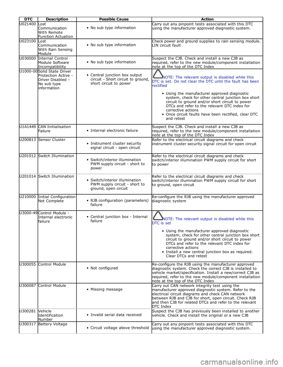
DTC Description Possible Cause Action U021400
Lost
Communication
With Remote
Function Actuation
No sub type information Carry out any pinpoint tests associated with this DTC
using the manufacturer approved diagnostic system. U023100
Lost
Communication
With Rain Sensing
Module
No sub type information Check power and ground supplies to rain sensing module.
LIN circuit fault U030000
Internal Control
Module Software Incompatibility
No sub type information Suspect the CJB. Check and install a new CJB as
required, refer to the new module/component installation
note at the top of the DTC Index U1000-00
Solid State Driver
Protection Active -
Driver Disabled -
No sub type
information
Central junction box output
circuit - Short circuit to ground,
short circuit to power
NOTE: The relevant output is disabled while this
DTC is set. Do not clear the DTC until the fault has been
rectified
Using the manufacturer approved diagnostic
system, check for other central junction box short
circuit to ground and/or short circuit to power
DTCs and refer to the relevant DTC index for
corrective actions
Once circuit faults have been rectified, clear DTC
and retest U1A1449
CAN Initialisation
Failure
Internal electronic failure Suspect the CJB. Check and install a new CJB as
required, refer to the new module/component installation
note at the top of the DTC Index U200813 Sensor Cluster
Instrument cluster security
signal circuit - open circuit Refer to the electrical circuit diagrams and check
instrument cluster security signal circuit for open circuit U201012 Switch Illumination
Switch/interior illumination
PWM supply circuit - short to
power Refer to the electrical circuit diagrams and check
switch/interior illumination PWM supply circuit for short
to power U201014 Switch Illumination
Switch/interior illumination
PWM supply circuit - short to
ground, open circuit Refer to the electrical circuit diagrams and check
switch/interior illumination PWM supply circuit for short
to ground, open circuit U210000
Initial Configuration
Not Complete
RJB configuration (parameters)
failure Re-configure the RJB using the manufacturer approved
diagnostic system U3000-49
Control Module -
Internal electronic
failure
Central junction box - Internal
failure
NOTE: The relevant output is disabled while this
DTC is set
Using the manufacturer approved diagnostic
system, check for other central junction box short
circuit to ground and/or short circuit to power
DTCs and refer to the relevant DTC index for
corrective actions
Install a new central junction box as required.
Clear DTCs and retest U300055 Control Module
Not configured Re-configure the RJB using the manufacturer approved
diagnostic system. Check the correct CJB is installed to
vehicle market/specification. Install a new/correct CJB as
required, refer to the new module/component installation
note at the top of the DTC Index U300087 Control Module
Missing message Carry out CAN network integrity test using the
manufacturer approved diagnostic system. Refer to the
electrical circuit diagrams and check CAN network
between RJB and CJB for short, open circuit. Check RJB
and then CJB for related DTCs and refer to the relevant
DTC Index U300281
Vehicle
Identification
Number
Invalid serial data received Suspect the CJB has previously been installed to another
vehicle. Check and install the original or a new CJB U300317 Battery Voltage
Circuit voltage above threshold Carry out any pinpoint tests associated with this DTC
using the manufacturer approved diagnostic system.
Page 2093 of 3039
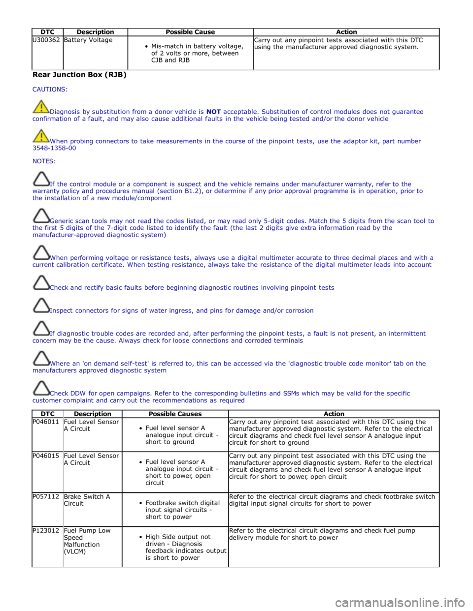
DTC Description Possible Cause Action U300362 Battery Voltage
Mis-match in battery voltage,
of 2 volts or more, between
CJB and RJB Carry out any pinpoint tests associated with this DTC
using the manufacturer approved diagnostic system. Rear Junction Box (RJB)
CAUTIONS:
Diagnosis by substitution from a donor vehicle is NOT acceptable. Substitution of control modules does not guarantee
confirmation of a fault, and may also cause additional faults in the vehicle being tested and/or the donor vehicle
When probing connectors to take measurements in the course of the pinpoint tests, use the adaptor kit, part number
3548-1358-00
NOTES:
If the control module or a component is suspect and the vehicle remains under manufacturer warranty, refer to the
warranty policy and procedures manual (section B1.2), or determine if any prior approval programme is in operation, prior to
the installation of a new module/component
Generic scan tools may not read the codes listed, or may read only 5-digit codes. Match the 5 digits from the scan tool to
the first 5 digits of the 7-digit code listed to identify the fault (the last 2 digits give extra information read by the
manufacturer-approved diagnostic system)
When performing voltage or resistance tests, always use a digital multimeter accurate to three decimal places and with a
current calibration certificate. When testing resistance, always take the resistance of the digital multimeter leads into account
Check and rectify basic faults before beginning diagnostic routines involving pinpoint tests
Inspect connectors for signs of water ingress, and pins for damage and/or corrosion
If diagnostic trouble codes are recorded and, after performing the pinpoint tests, a fault is not present, an intermittent
concern may be the cause. Always check for loose connections and corroded terminals
Where an 'on demand self-test' is referred to, this can be accessed via the 'diagnostic trouble code monitor' tab on the
manufacturers approved diagnostic system
Check DDW for open campaigns. Refer to the corresponding bulletins and SSMs which may be valid for the specific
customer complaint and carry out the recommendations as required
DTC Description Possible Causes Action P046011
Fuel Level Sensor
A Circuit
Fuel level sensor A
analogue input circuit -
short to ground Carry out any pinpoint test associated with this DTC using the
manufacturer approved diagnostic system. Refer to the electrical
circuit diagrams and check fuel level sensor A analogue input
circuit for short to ground P046015
Fuel Level Sensor
A Circuit
Fuel level sensor A
analogue input circuit -
short to power, open
circuit Carry out any pinpoint test associated with this DTC using the
manufacturer approved diagnostic system. Refer to the electrical
circuit diagrams and check fuel level sensor A analogue input
circuit for short to power, open circuit P057112
Brake Switch A
Circuit
Footbrake switch digital
input signal circuits -
short to power Refer to the electrical circuit diagrams and check footbrake switch
digital input signal circuits for short to power P123012
Fuel Pump Low
Speed
Malfunction
(VLCM)
High Side output not
driven - Diagnosis
feedback indicates output
is short to power Refer to the electrical circuit diagrams and check fuel pump
delivery module for short to power
Page 2101 of 3039
Published: 11-May-2011
Module Communications Network - Auxiliary Junction Box (AJB)
Removal and Installation
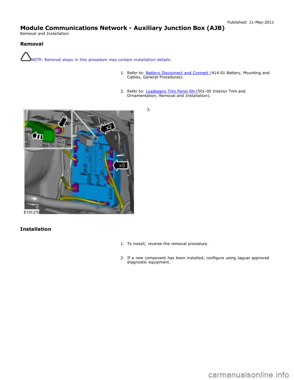
Removal
NOTE: Removal steps in this procedure may contain installation details.
1. Refer to: Battery Disconnect and Connect (414-01 Battery, Mounting and Cables, General Procedures).
2. Refer to: Loadspace Trim Panel RH (501-05 Interior Trim and Ornamentation, Removal and Installation).
3.
Installation
1. To install, reverse the removal procedure.
2. If a new component has been installed, configure using Jaguar approved
diagnostic equipment.
Page 2102 of 3039

Module Communications Network - Central Junction Box (CJB)
Removal and Installation
Removal
NOTE: Removal steps in this procedure may contain installation details.
All vehicles Published: 11-May-2011
1. Refer to: Battery Disconnect and Connect (414-01 Battery, Mounting and Cables, General Procedures).
2. Refer to: Cowl Side Trim Panel (501-05 Interior Trim and Ornamentation, Removal and Installation).
Left-hand drive vehicles
3.
Page 2121 of 3039

Anti-Theft - Active - Anti-Theft - Active - Overview
Description and Operation
Overview Published: 11-May-2011
The active anti-theft system is available with three different levels of vehicle protection depending on market specification:
Hinged panel sensing
Hinged panel and intrusion sensing
Hinged panel, intrusion and inclination sensing.
The CJB (central junction box) automatically arms and disarms the active anti-theft system when it functions the central
locking system.
Refer to: Handles, Locks, Latches and Entry Systems (501-14 Handles, Locks, Latches and Entry Systems, Description and Operation).
Depending on market specification two modes of protection are used: perimeter mode and volumetric mode.
Perimeter mode
Perimeter mode, monitors the security of the hinged panels, which include:
all doors,
luggage compartment lid, and
engine compartment lid.
When perimeter mode is active, the CJB monitors the panel ajar switches in the latch mechanisms of the hinged panels.
Volumetric mode
In volumetric mode the CJB monitors the interior of the vehicle for movement using an ultrasonic sound wave sensor.
If the battery backed sounder incorporates an inclination sensor the vehicle will also be monitored for unauthorised tilting; for
example towing or jacking.
Page 2122 of 3039
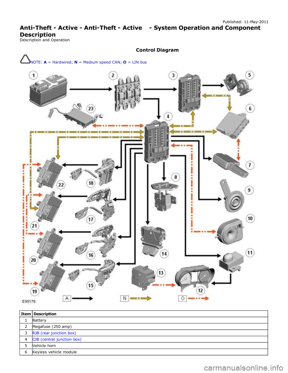
Published: 11-May-2011
Anti-Theft - Active - Anti-Theft - Active - System Operation and Component Description
Description and Operation
Control Diagram
NOTE: A = Hardwired; N = Medium speed CAN; O = LIN bus
Item Description 1 Battery 2 Megafuse (250 amp) 3 RJB (rear junction box) 4 CJB (central junction box) 5 Vehicle horn 6 Keyless vehicle module