Engine JAGUAR XFR 2010 1.G Workshop Manual
[x] Cancel search | Manufacturer: JAGUAR, Model Year: 2010, Model line: XFR, Model: JAGUAR XFR 2010 1.GPages: 3039, PDF Size: 58.49 MB
Page 977 of 3039

Engine - V8 S/C 5.0L Petrol - Exhaust Manifold RH
Removal and Installation
Special Tool(s)
303-1444-01
Exhaust Manifold Installation Guide Pins - Threaded
303-1444-02
Exhaust Manifold Installation Guide Pins - Unthreaded Removal Published: 11-May-2011
NOTE: Some variation in the illustrations may occur, but the essential information is always correct.
All vehicles
1. Refer to: Battery Disconnect and Connect (414-01 Battery, Mounting and Cables, General Procedures).
2. NOTE: Do not work on or under a vehicle supported only by a jack.
Always support the vehicle on safety stands.
Raise and support the vehicle.
3. Refer to: Catalytic Converter RH (309-00C Exhaust System - V8 5.0L Petrol/V8 S/C 5.0L Petrol, Removal and Installation).
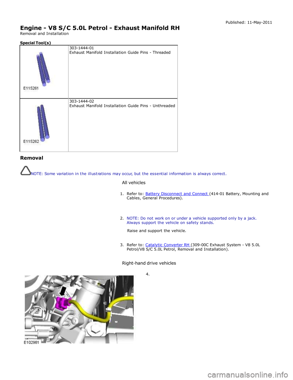
Right-hand drive vehicles
4.
Page 985 of 3039

Engine - V8 S/C 5.0L Petrol - Flexplate
Removal and Installation
Removal
NOTE: Removal steps in this procedure may contain installation details. Published: 11-May-2011
1. Refer to: Battery Disconnect and Connect (414-01 Battery, Mounting and Cables, General Procedures).
2. CAUTION: Make sure to support the vehicle with axle stands.
Raise and support the vehicle.
3. Refer to: Transmission - V8 5.0L Petrol/V8 S/C 5.0L Petrol (307-01B Automatic Transmission/Transaxle - TDV6 3.0L Diesel /V8 5.0L Petrol/V8
S/C 5.0L Petrol, Removal).
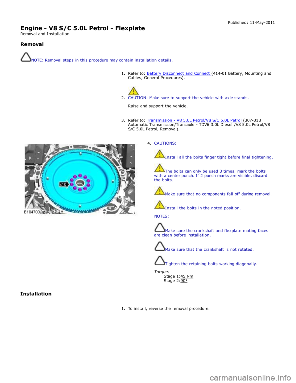
4. CAUTIONS:
Install all the bolts finger tight before final tightening.
The bolts can only be used 3 times, mark the bolts
with a center punch. If 2 punch marks are visible, discard
the bolts.
Make sure that no components fall off during removal.
Install the bolts in the noted position.
NOTES:
Make sure the crankshaft and flexplate mating faces
are clean before installation.
Make sure that the crankshaft is not rotated.
Tighten the retaining bolts working diagonally.
Torque:
Stage 1:45 Nm Stage 2:90°
Installation
1. To install, reverse the removal procedure.
Page 986 of 3039

Engine - V8 S/C 5.0L Petrol - Oil Cooler
Removal and Installation
Removal
NOTE: Removal steps in this procedure may contain installation details. Published: 19-Nov-2013
1. Refer to: Battery Disconnect and Connect (414-01 Battery, Mounting and Cables, General Procedures).
2. WARNING: Make sure to support the vehicle with axle stands.
Raise and support the vehicle.
3. Refer to: Cooling System Partial Draining, Filling and Bleeding - V8 S/C 5.0L Petrol (303-03C Engine Cooling - V8 5.0L Petrol/V8 S/C 5.0L Petrol, General Procedures).
4. Refer to: Supercharger (303-12D Intake Air Distribution and Filtering - V8 S/C 5.0L Petrol, Removal and Installation).
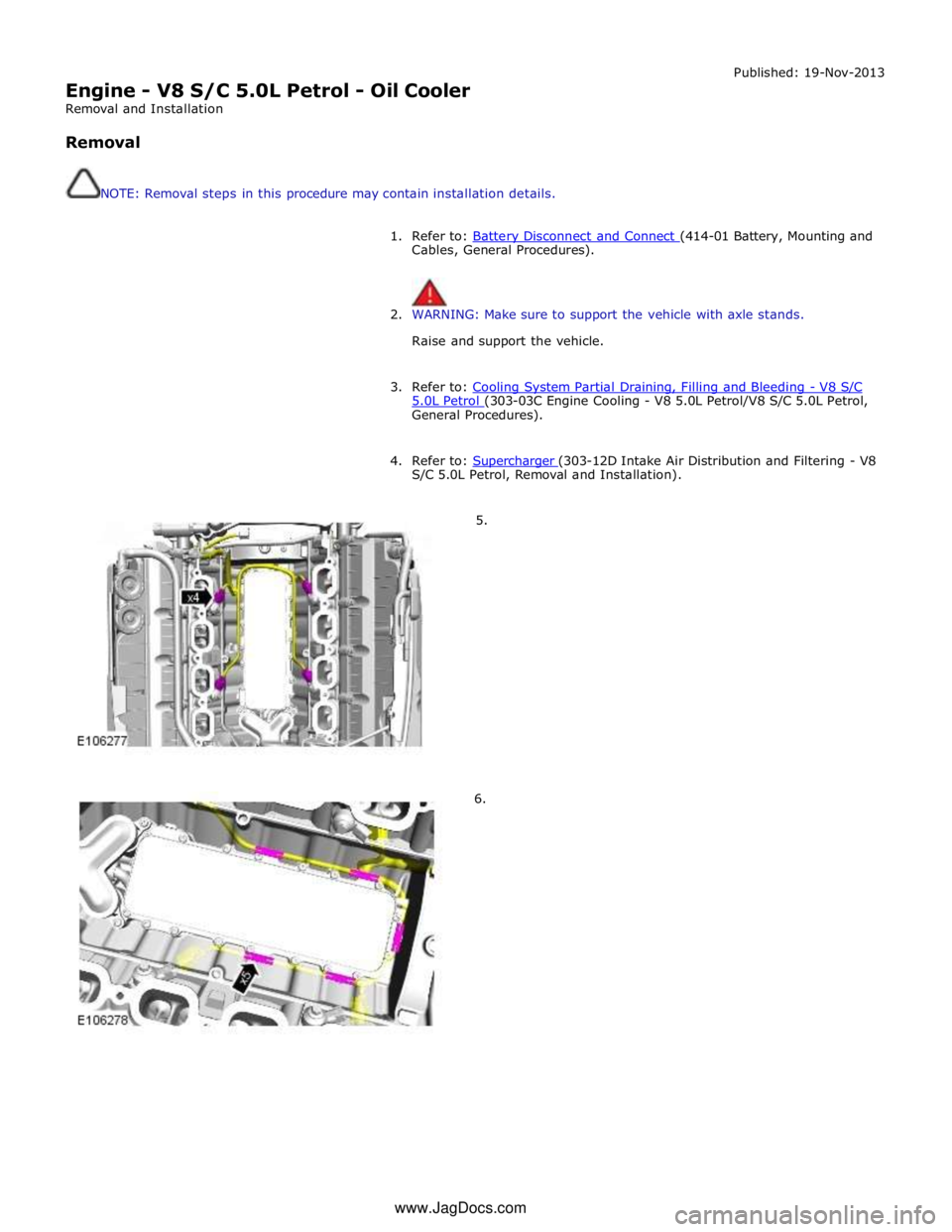
5.
6. www.JagDocs.com
Page 989 of 3039

Engine - V8 S/C 5.0L Petrol - Oil Filter Element
Removal and Installation
Removal Published: 11-May-2011
NOTE: Some variation in the illustrations may occur, but the essential information is always correct.
1. Refer to: Engine Cover - V8 5.0L Petrol/V8 S/C 5.0L Petrol (501-05 Interior Trim and Ornamentation, Removal and Installation).
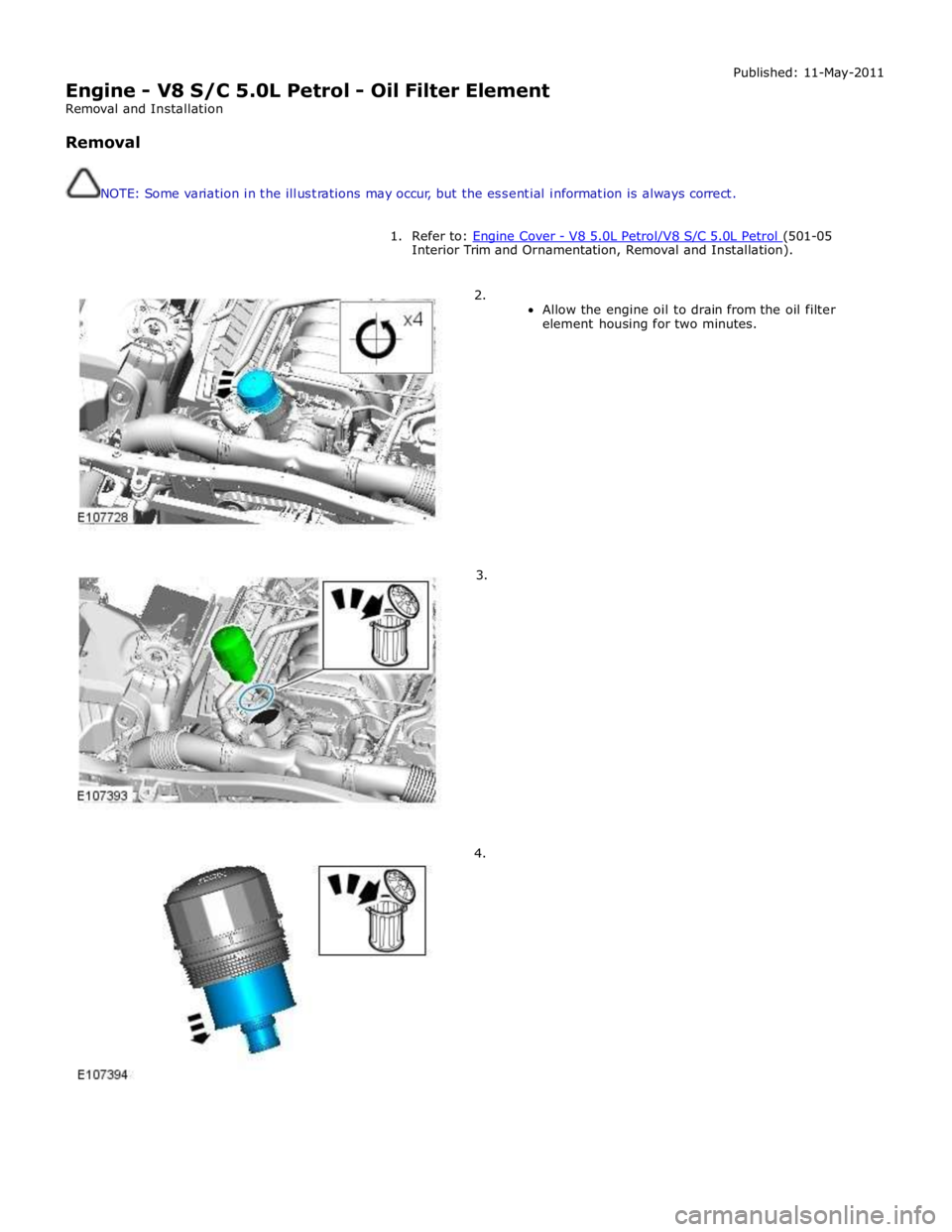
2.
Allow the engine oil to drain from the oil filter
element housing for two minutes.
3.
4.
Page 990 of 3039

3. Check and top-up the engine oil.
4. Start and run the engine.
5. Refer to: Engine Cover - V8 5.0L Petrol/V8 S/C 5.0L Petrol (501-05 Interior Trim and Ornamentation, Removal and Installation). Installation
Page 991 of 3039

Engine - V8 S/C 5.0L Petrol - Oil Pan
Removal and Installation
Removal
NOTE: Removal steps in this procedure may contain installation details. Published: 11-May-2011
1. Refer to: Battery Disconnect and Connect (414-01 Battery, Mounting and Cables, General Procedures).
2. WARNING: Make sure to support the vehicle with axle stands.
Raise and support the vehicle.
3. Refer to: Engine Oil Level Sensor (303-14D Electronic Engine Controls - V8 S/C 5.0L Petrol, Removal and Installation).
4. www.JagDocs.com
Page 992 of 3039

Installation
1. CAUTIONS:
Use only a plastic scraper when removing the sealing
material.
Use lint free cloth.
Make sure that the mating faces are clean and free of
corrosion and foreign material.
Apply RTV sealant WSE-M4G323-A6 (Loctite 5901G)
to the areas shown, and tighten the bolts within 7
minutes.
Apply a bead of sealant, 2.5 mm diameter, to the
area indicated.
2. NOTE: Tighten the bolts in the sequence shown.
Torque: 12 Nm
3. Refer to: Engine Oil Level Sensor (303-14D Electronic Engine Controls - V8 S/C 5.0L Petrol, Removal and Installation).
Page 993 of 3039

303-1442
Rear Crankshaft Seal Installer
303-1443
Rear Crankshaft Cover Alignment Tool Removal
NOTES:
Removal steps in this procedure may contain installation details.
Some variation in the illustrations may occur, but the essential information is always correct. Published: 03-Dec-2011
1. Refer to: Battery Disconnect and Connect (414-01 Battery, Mounting and Cables, General Procedures).
2. WARNING: Do not work on or under a vehicle supported only by a jack. Always
support the vehicle on safety stands.
Raise and support the vehicle.
3. Refer to: Crankshaft Pulley (303-01D Engine - V8 S/C 5.0L Petrol, Removal and Installation).
4. Refer to: Engine (303-01D Engine - V8 S/C 5.0L Petrol, Installation).
Page 1007 of 3039

15.
16.
17.
18. Torque: 11 Nm
Torque: 11 Nm
NOTE: Lubricate the fuel rail high-pressure fuel pump bucket with clean
engine oil.
CAUTION: Tighten the Torx screws a turn at a time until the correct
torque is achieved.
NOTE: Lubricate the fuel rail high-pressure fuel pump O-ring seal with
clean engine oil.
Torque: 11 Nm
Page 1008 of 3039

19.
20.
21.
22. Loosen the Torx screws half a turn each.
NOTE: Lubricate the fuel rail high-pressure fuel pump bucket with clean
engine oil.
CAUTION: Tighten the Torx screws a turn at a time until the correct
torque is achieved.
NOTE: Lubricate the fuel rail high-pressure fuel pump O-ring seal with
clean engine oil.
Torque: 11 Nm