JAGUAR XFR 2010 1.G Workshop Manual
XFR 2010 1.G
JAGUAR
JAGUAR
https://www.carmanualsonline.info/img/21/7642/w960_7642-0.png
JAGUAR XFR 2010 1.G Workshop Manual
Trending: TPMS, Crank, airbag disable, warning light, tire size, dimensions, u0140
Page 2001 of 3039
Published: 11-May-2011
Information and Entertainment System - Steering Wheel Audio Controls
Removal and Installation
Removal
NOTE: Removal steps in this procedure may contain installation details.
1. Make the SRS system safe.
Refer to: Standard Workshop Practices (100-00 General Information, Description and Operation).
2. Refer to: Driver Air Bag Module (501-20B Supplemental Restraint System, Removal and Installation).
3. Refer to: Upshift Paddle Switch (307-05A Automatic Transmission/Transaxle External Controls - V6 3.0L Petrol, Removal and
Installation).
4. Refer to: Downshift Paddle Switch (307-05A Automatic Transmission/Transaxle External Controls - V6 3.0L Petrol, Removal and
Installation).
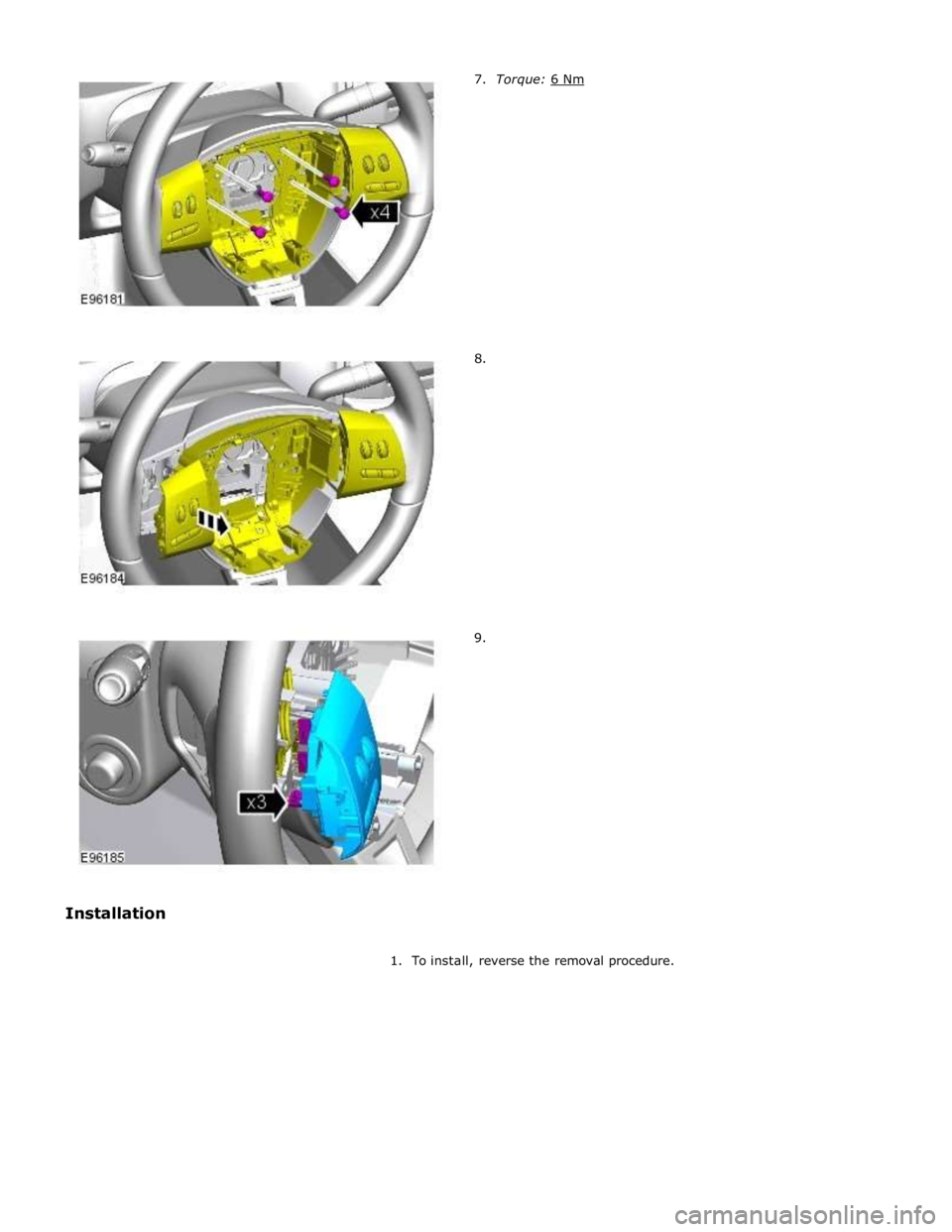
5. Torque: 3 Nm 6. Torque: 3 Nm
Page 2002 of 3039
8.
9.
1. To install, reverse the removal procedure.
Page 2003 of 3039
Information and Entertainment System - Subwoofer Amplifier
Removal and Installation
Removal
NOTE: Removal steps in this procedure may contain installation details. Published: 11-May-2011
1. Refer to: Battery Disconnect and Connect (414-01 Battery, Mounting and Cables, General Procedures).
2. Refer to: Loadspace Trim Panel LH (501-05 Interior Trim and Ornamentation, Removal and Installation).
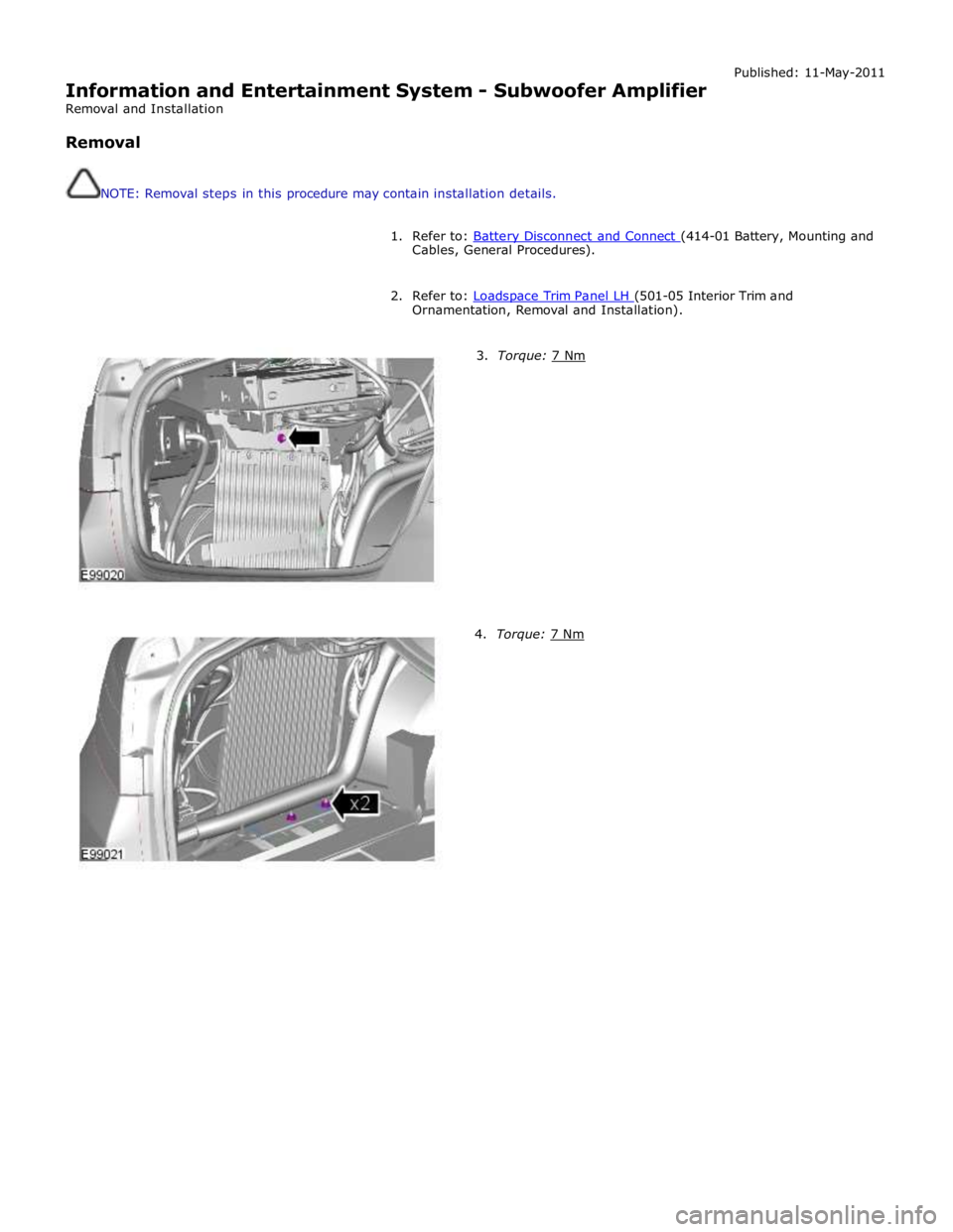
3. Torque: 7 Nm 4. Torque: 7 Nm
Page 2004 of 3039
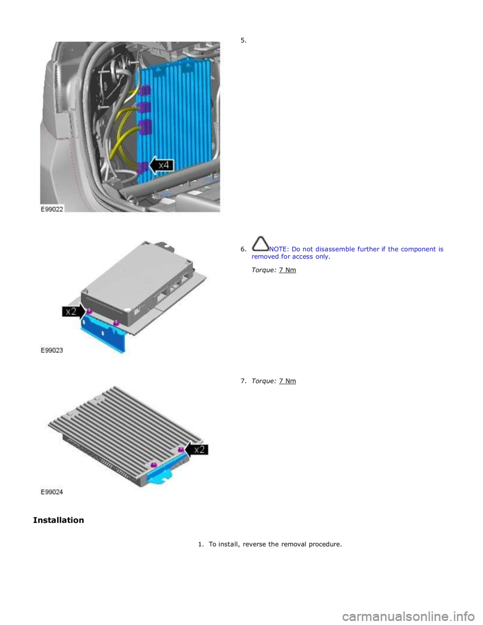
7. Torque: 7 Nm
1. To install, reverse the removal procedure.
Page 2005 of 3039
Information and Entertainment System - Subwoofer Speaker
Removal and Installation
Removal
NOTE: Removal steps in this procedure may contain installation details. Published: 11-May-2011
1. Refer to: Battery Disconnect and Connect (414-01 Battery, Mounting and Cables, General Procedures).
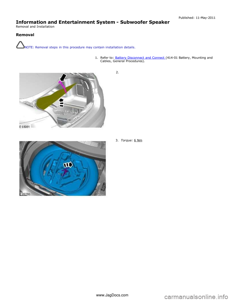
2.
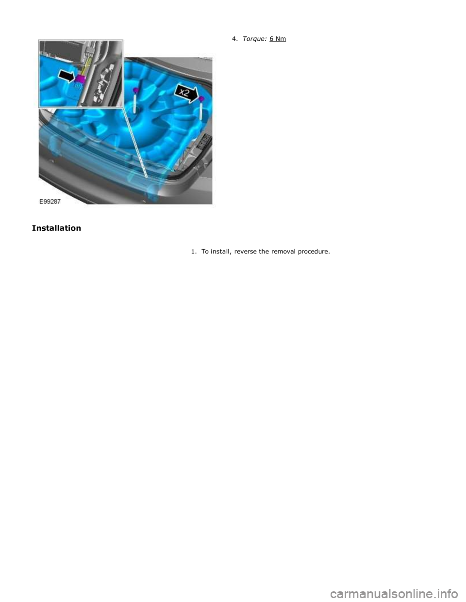
3. Torque: 6 Nm www.JagDocs.com
Page 2006 of 3039
1. To install, reverse the removal procedure.
Page 2007 of 3039
Information and Entertainment System - Satellite Radio Tuner
Removal and Installation
Removal
NOTES:
Removal steps in this procedure may contain installation details.
Some variation in the illustrations may occur, but the essential information is always correct. Published: 09-Dec-2012
1. Disconnect the battery ground cable.
Refer to: Battery Disconnect and Connect (414-01 Battery, Mounting and Cables, General Procedures).
2. Refer to: Front Seat (501-10 Seating, Removal and Installation).
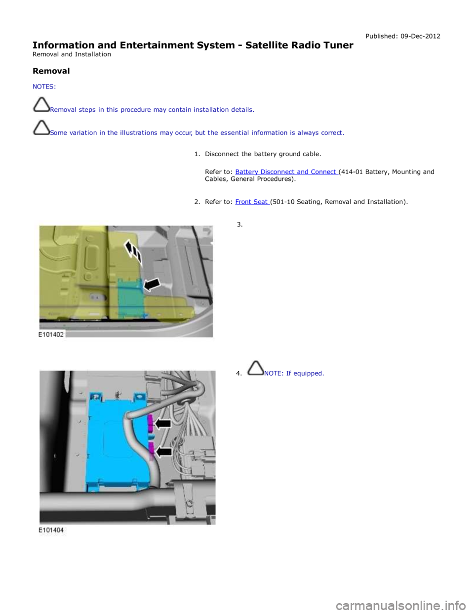
3.
4. NOTE: If equipped.
Page 2008 of 3039
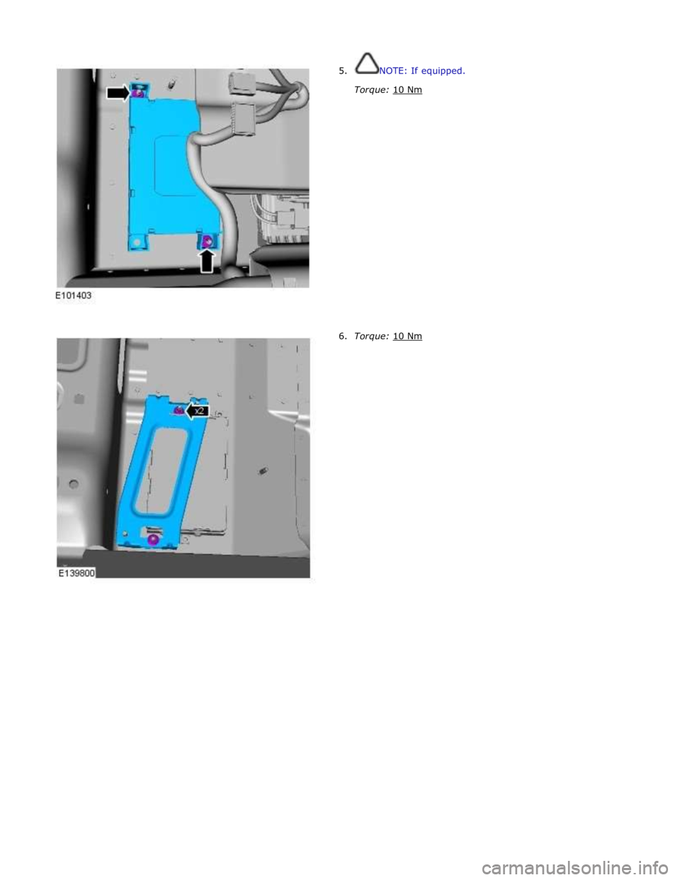
5. NOTE: If equipped.
Torque: 10 Nm
6. Torque: 10 Nm
Page 2009 of 3039
7.
Installation
1. NOTE: If a new component is installed, a link lead must
be installed to the module in the position shown.
2. To install, reverse the removal procedure.
Page 2010 of 3039

Published: 23-Jan-2012
Information and Entertainment System - DTC: Audio Input Control Module - Audio Input Control Module
Diagnosis and Testing
Principle of Operation
This section of the manual concerns diagnostic procedures for the Dension audio input control module. For a detailed
description of the information and entertainment system, refer to the relevant description and operation sections in the
workshop manual
Inspection and Verification
CAUTION: Diagnosis by substitution from a donor vehicle is NOT acceptable. Substitution of control modules does not
guarantee confirmation of a fault, and may also cause additional faults in the vehicle being tested and/or the donor vehicle
1. Verify the customer concern
2. Visually inspect for obvious signs of damage and system integrity
Visual Inspection
Mechanical Electrical
Audio input control module
Audio amplifier module
Integrated audio module
Integrated control panel
Touch screen display
Loudspeakers
Fuses
Loose or corroded connector(s)
Audio amplifier module
Integrated audio module
Integrated control panel
Touch screen display
Loudspeakers
3. If an obvious cause for an observed or reported concern is found, correct the cause (if possible) before proceeding to
the next step
4. If the cause is not visually evident, check for diagnostic trouble codes and refer to the relevant diagnostic trouble codes
index
Audio Input Control Module Diagnostics
NOTE: If problems are reported with the audio input control module, prior to further diagnostic checks or replacement of
components, first perform a hardware reset by depressing the reset button for a minimum of two seconds. If problems persist,
refer to the symptom charts below
Performing A Hardware Reset
Symptom Chart - Intermittent Fault With iPOD® Playback
Symptom Possible Cause Action Intermittent fault
with iPOD®
playback
The connected iPOD® unit has
crashed or frozen
See diagnostic procedures as specified in pinpoint test A1
"Check The Operation Of The iPOD®" below GO to
Pinpoint Test A. www.JagDocs.com
Trending: oil, wheel, super charger, u0001-87, p 0480, ESP inoperative, B1C33-14

