JAGUAR XFR 2010 1.G Workshop Manual
Manufacturer: JAGUAR, Model Year: 2010, Model line: XFR, Model: JAGUAR XFR 2010 1.GPages: 3039, PDF Size: 58.49 MB
Page 291 of 3039
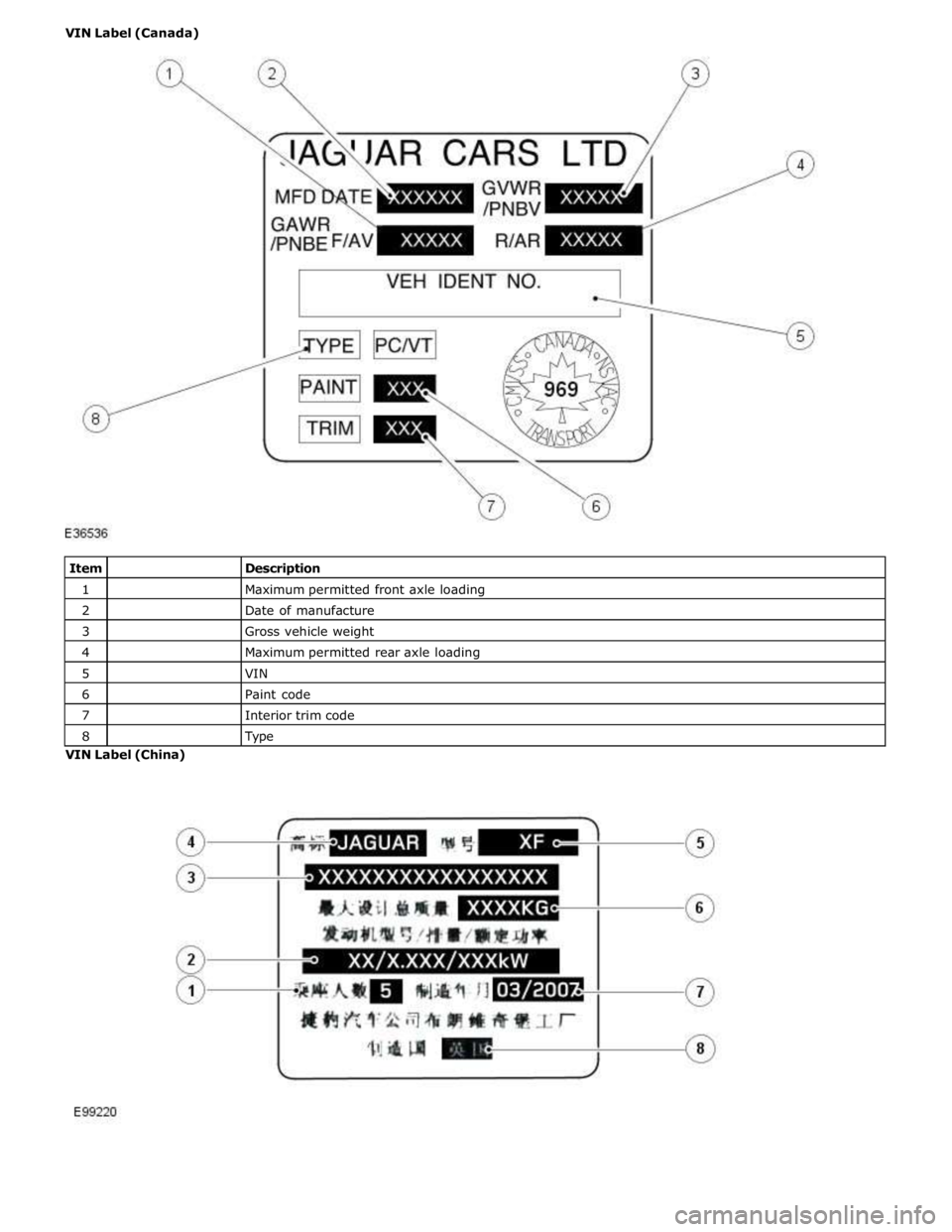
1
Maximum permitted front axle loading 2
Date of manufacture 3
Gross vehicle weight 4
Maximum permitted rear axle loading 5
VIN 6
Paint code 7
Interior trim code 8
Type VIN Label (China)
Page 292 of 3039
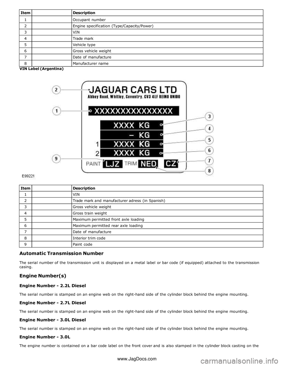
1
Occupant number 2
Engine specification (Type/Capacity/Power) 3
VIN 4
Trade mark 5
Vehicle type 6
Gross vehicle weight 7
Date of manufacture 8
Manufacturer name VIN Label (Argentina)
Item
Description 1
VIN 2
Trade mark and manufacturer adress (in Spanish) 3
Gross vehicle weight 4
Gross train weight 5
Maximum permitted front axle loading 6
Maximum permitted rear axle loading 7
Date of manufacture 8
Interior trim code 9
Paint code Automatic Transmission Number
The serial number of the transmission unit is displayed on a metal label or bar code (if equipped) attached to the transmission
casing.
Engine Number(s)
Engine Number - 2.2L Diesel
The serial number is stamped on an engine web on the right-hand side of the cylinder block behind the engine mounting.
Engine Number - 2.7L Diesel
The serial number is stamped on an engine web on the right-hand side of the cylinder block behind the engine mounting.
Engine Number - 3.0L Diesel
The serial number is stamped on an engine web on the right-hand side of the cylinder block behind the engine mounting.
Engine Number - 3.0L
The engine number is contained on a bar code label on the front cover and is also stamped in the cylinder block casting on the www.JagDocs.com
Page 293 of 3039

left-hand side of the engine below the engine mounting.
Engine Number - 4.2L and 4.2L Supercharged
The serial number is stamped on an engine web on the left-hand side of the cylinder block behind the engine mounting. The
emission code is also located here, on the transmission flange.
Engine Number - 5.0L and 5.0L Supercharged
The serial number is stamped on an engine web on the left-hand side of the cylinder block behind the engine mounting.
Page 294 of 3039

Jacking and Lifting - Jacking
Description and Operation
Safety Precautions Published: 11-May-2011
WARNING: The jack provided with the vehicle is intended to be used in an emergency for changing a deflated tire. To
avoid damage to the vehicle, never use the jack to raise the vehicle for any other purpose. Refer to the Driver Handbook when
using the jack supplied with the vehicle. Failure to follow these instructions may result in personal injury.
The following safety precautions must be observed when raising the vehicle to carry out service operations:
Never rely on a jack alone to support a vehicle. Always use suitable vehicle stands to provide rigid support.
When working beneath a vehicle, whenever possible use a vehicle hoist instead of a jack and vehicle stands.
Make sure that the vehicle is standing on firm, level ground before using a jack.
Do not rely on the parking brake alone; chock the wheels and put the automatic transmission into Park if possible.
Check that any lifting equipment used has adequate capacity for the load being lifted and is in correct working order.
Page 295 of 3039
Jacking and Lifting - Lifting
Description and Operation
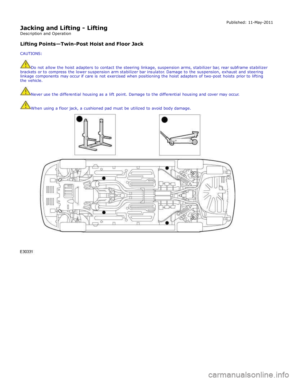
Lifting Points—Twin-Post Hoist and Floor Jack
CAUTIONS: Published: 11-May-2011
Do not allow the hoist adapters to contact the steering linkage, suspension arms, stabilizer bar, rear subframe stabilizer
brackets or to compress the lower suspension arm stabilizer bar insulator. Damage to the suspension, exhaust and steering
linkage components may occur if care is not exercised when positioning the hoist adapters of two-post hoists prior to lifting
the vehicle.
Never use the differential housing as a lift point. Damage to the differential housing and cover may occur.
When using a floor jack, a cushioned pad must be utilized to avoid body damage.
Page 296 of 3039
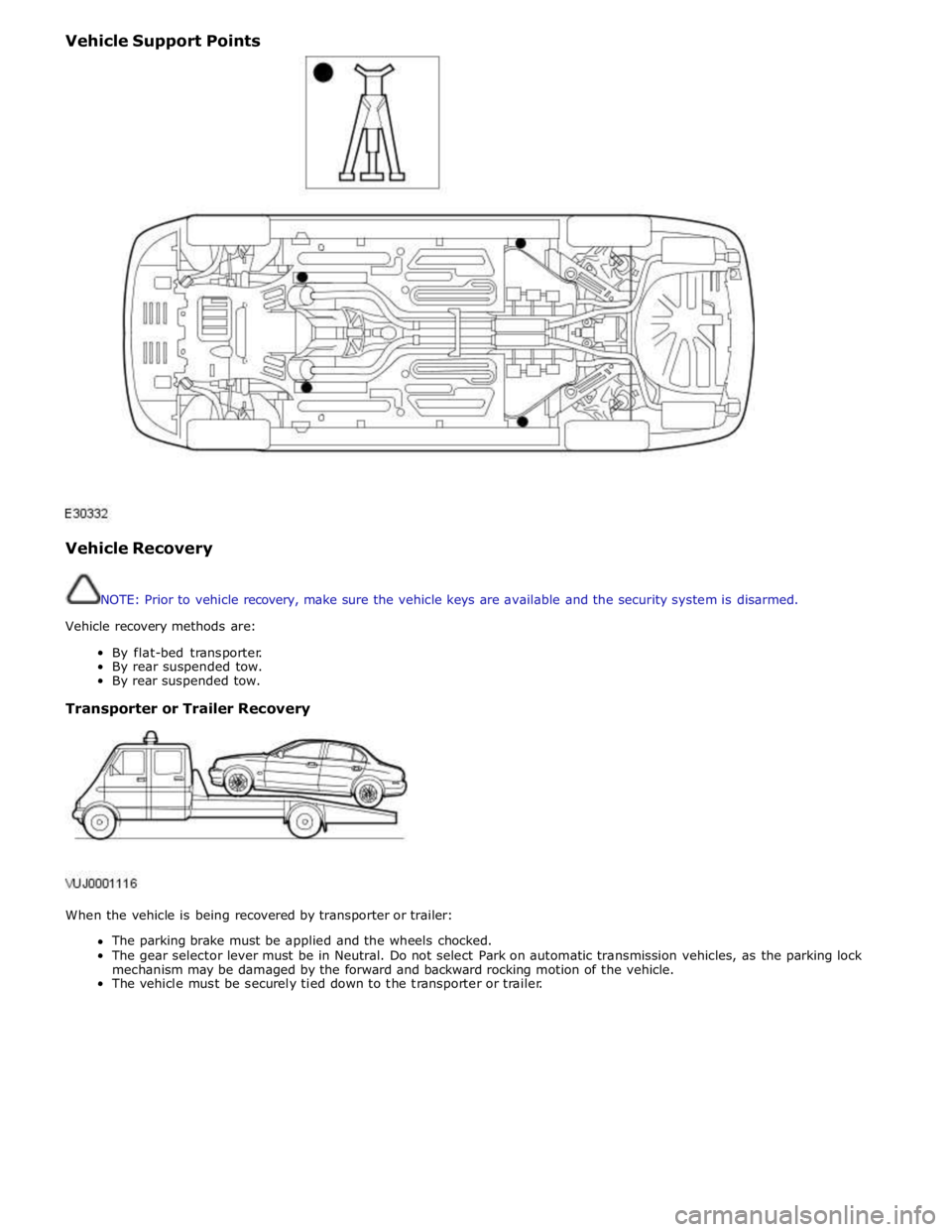
Vehicle Support Points
Vehicle Recovery
NOTE: Prior to vehicle recovery, make sure the vehicle keys are available and the security system is disarmed.
Vehicle recovery methods are:
By flat-bed transporter.
By rear suspended tow.
By rear suspended tow.
Transporter or Trailer Recovery
When the vehicle is being recovered by transporter or trailer:
The parking brake must be applied and the wheels chocked.
The gear selector lever must be in Neutral. Do not select Park on automatic transmission vehicles, as the parking lock
mechanism may be damaged by the forward and backward rocking motion of the vehicle.
The vehicle must be securely tied down to the transporter or trailer.
Page 297 of 3039
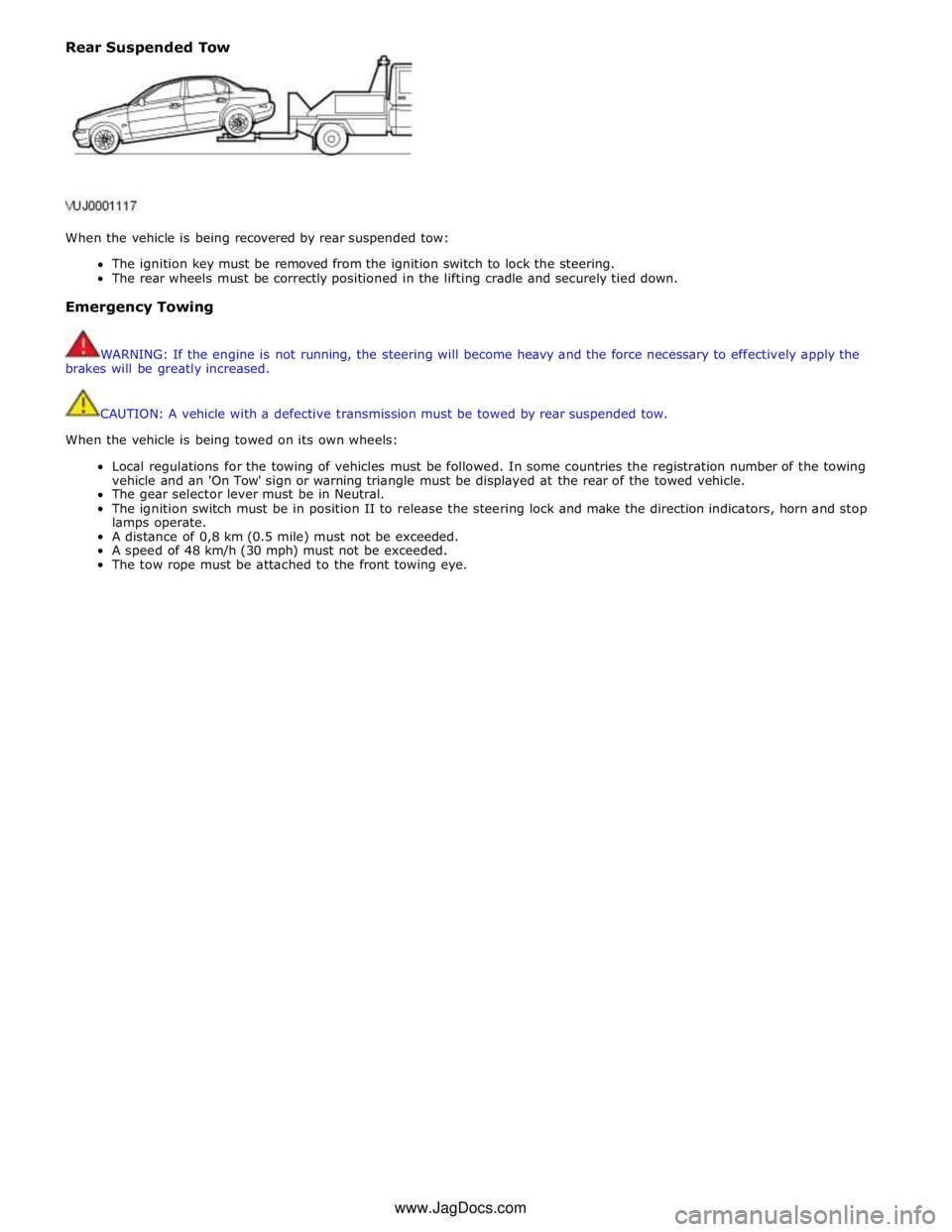
Rear Suspended Tow
When the vehicle is being recovered by rear suspended tow:
The ignition key must be removed from the ignition switch to lock the steering.
The rear wheels must be correctly positioned in the lifting cradle and securely tied down.
Emergency Towing
WARNING: If the engine is not running, the steering will become heavy and the force necessary to effectively apply the
brakes will be greatly increased.
CAUTION: A vehicle with a defective transmission must be towed by rear suspended tow.
When the vehicle is being towed on its own wheels:
Local regulations for the towing of vehicles must be followed. In some countries the registration number of the towing
vehicle and an 'On Tow' sign or warning triangle must be displayed at the rear of the towed vehicle.
The gear selector lever must be in Neutral.
The ignition switch must be in position II to release the steering lock and make the direction indicators, horn and stop
lamps operate.
A distance of 0,8 km (0.5 mile) must not be exceeded.
A speed of 48 km/h (30 mph) must not be exceeded.
The tow rope must be attached to the front towing eye. www.JagDocs.com
Page 298 of 3039

Published: 11-May-2011
Noise, Vibration and Harshness - Noise, Vibration and Harshness (NVH)
Description and Operation
Noise, vibration and harshness (NVH) is becoming more important as vehicles become more sophisticated and passenger
comfort levels increase. This section is designed to aid in the diagnosis, testing and repair of NVH concerns.
Noise is defined as sounds not associated with the operation of passenger compartment equipment that interface with
customer satisfaction.
Vibration is defined as impulses felt by the customer that are not caused by road surface changes.
Harshness is a ride quality issue where the customer feels that the vehicle response to the road surface is sharply
transmitted to the customer.
Diagnostic Theory
Diagnosis is more than just following a series of interrelated steps in order to find the solution to the specific condition. It is a
way of looking at systems that are not functioning the way they should and finding out why. Also it is knowing how the system
should work and whether it is working correctly.
There are basic rules for diagnosis. If these rules are followed, the cause of the condition is usually found the first time
through the system.
Know the System
Know how the parts go together.
Know how the system operates as well as its limits and what happens when the system goes wrong.
Sometimes this means checking the system against one that is known to be working correctly.
Know the History of the System
A clue in any one of these areas may save time:
How old or new is the system?
What kind of treatment has it had?
Has it been repaired in the past in such a manner that might relate to the present condition?
What is the repair history?
Know the History of the Condition
Did it start suddenly or appear gradually?
Was it related to some other occurrence such as a collision or previous part renewal?
Know how the condition made itself known; it may be an important clue to the cause.
Know the Probability of Certain Conditions Developing
Look for the simple rather than the complex.
For example:
- Electrical conditions usually occur at connections rather than components.
- An engine no-start is more likely to be caused by a loose wire or small adjustment rather than a sheared-off
camshaft.
Know the difference between impossible and improbable. Certain failures in a system can be improbable but still
happen.
New parts are just that, new. It does not mean they are always good functioning parts.
Do Not Cure the Symptom and Leave the Cause
Lowering the pressure in a front tire may correct the condition of a vehicle leaning to one side, but it does not correct the
original condition.
Be Positive the Cause is Found
Double check the findings.
What caused a worn component?
A loose transmission or engine mount could indicate that other mounts are also loose.
Diagnostic Charts
Charts are a simple way of expressing the relationship between basic logic and a physical system of components. They help
discover the cause of a condition in the least time. Diagnostic charts combine many areas of diagnosis into one visual display:
probability of certain things occurring in a system
speed of checking certain components or functions before others
simplicity of carrying out certain tests before others
elimination of checking huge portions of a system by carrying out simple tests
certainty of narrowing down the search to a small portion before carrying out in-depth testing
The fastest way to find a condition is to work with the tools that are available. This means working with proven diagnostic
charts and the correct special equipment for the system.
Page 299 of 3039

Published: 16-Sep-2013
Noise, Vibration and Harshness - Noise, Vibration and Harshness (NVH)
Diagnosis and Testing
Principle of Operation
For a detailed description of Noise, Vibration and Harshness issues, refer to the Description and Operation section of the
workshop manual.
REFER to: Noise, Vibration and Harshness (NVH) (100-04 Noise, Vibration and Harshness, Description and Operation).
Inspection and Verification
1. Verify the customer's concerns by operating the vehicle to duplicate the condition.
2. Visually inspect the vehicle to determine any obvious cause(s) of the concern(s).
3. If the inspection reveals obvious causes that can be readily identified, repair as necessary.
4. If the concern(s) remains after the inspection, determine the symptom(s) and refer to the Symptom Chart.
How To Use This Diagnostic Procedure Section
Noise, vibration and harshness (NVH) concerns have become more important as vehicles have become more sensitive to
these vibrations. This section is designed as an aid to identifying these situations
The section provides diagnostic procedures based on symptoms. If the condition occurs at high speed, for instance, the
most likely place to start is under High Speed Shake
The road test procedure will tell how to sort the conditions into categories and how to tell a vibration from a shake
A series of Road Test Quick Checks is provided to make sure that a cause is either pinpointed or eliminated
Name the condition, proceed to the appropriate section and locate the correct diagnosis. When the condition is
identified, the job is partly done
Follow the diagnostic procedure as outlined
Quick Checks are described within the step, while more involved tests and adjustments are outlined in General
Procedures
Always follow each step exactly and make notes to recall important findings later
Customer Interview
The road test and customer interview (if available) provide information that will help identify the concerns and will provide
direction to the correct starting point for diagnosis.
Identify the Condition
NVH problems usually occur in a number of areas:
tires
engine accessories
suspension
driveline
air leakage (wind noise)
squeaks and rattles
heating ventilation and air conditioning (HVAC)
electrical (e.g. motor noise)
transmission
engine
It is important, therefore, that an NVH concern be isolated into its specific area(s) as soon as possible. The easiest and
quickest way to do this is to carry out the Road Test as outlined.
Noise Diagnostic Procedure
Non-Axle Noise
The five most important sources of non-axle noise are exhaust, tires, roof racks, trim and mouldings, and transmission.
Therefore, make sure that none of the following conditions are the cause of the noise before proceeding with a driveline tear
down and diagnosis.
Under certain conditions, the pitch of the exhaust may sound very much like gear noise. At other times, it can be
mistaken for a wheel bearing rumble
Tires, especially snow tires, can have a high pitched tread whine or roar, similar to gear noise. Radial tires, to some
degree, have this characteristic. Also, any non-standard tire with an unusual tread construction may emit a roar or
whine type noise
Trim and mouldings can also cause whistling or a whining noise
Clunk may be a metallic noise heard when the automatic transmission is engaged in reverse or drive, or it may occur
when the throttle is applied or released. It is caused by backlash somewhere in the driveline
Bearing rumble sounds like marbles being tumbled. This condition is usually caused by a damaged wheel bearing
Page 300 of 3039
Noise Conditions
Gear noise is typically a howling or whining due to gear damage or incorrect bearing preload. It can occur at various
speeds and driving conditions, or it can be continuous
Chuckle is a particular rattling noise that sounds like a stick against the spokes of a spinning bicycle wheel. It occurs
while decelerating from approximately 64 km/h (40 miles/h) and can usually be heard all the way to a stop. The
frequency varies with vehicle speed
Knock is very similar to chuckle, though it may be louder and occurs on acceleration or deceleration. The tear down will
disclose what has to be corrected
Check and rule out tires, exhaust and trim items before disassembling the transmission to diagnose and correct gear noise.
The noises described under Road Test usually have specific causes that can be diagnosed by observation as the unit is
disassembled. The initial clues are the type of noise heard on the road test and the driving conditions.
Vibration Conditions
wear. NOTE: New Constant Velocity (CV) joints should not be installed unless disassembly and inspection revealed unusual
Clicking, popping or grinding noises may be caused by the following:
Cut or damaged CV joint boots resulting in inadequate or contaminated lubricant in the outboard or inboard CV joint
bearing housings
Loose CV joint boot clamps
Another component contacting the rear drive half shaft
Worn, damaged or incorrectly installed wheel bearing, suspension or brake component
Vibration at highway speeds may be caused by the following:
Out-of-balance front or rear wheels
Out-of-round tires
Driveline imbalance
Driveline run-out (alignment)
NOTE: Rear drive half shafts are not balanced and are not likely to contribute to rotational vibration disturbance.
Shudder or vibration during acceleration (including from rest) may be caused by the following:
Driveline alignment
Excessively worn or damaged outboard or inboard CV joint bearing housing
Excessively high CV joint operating angles caused by incorrect ride height. Check ride height, verify correct spring rate
and check items under Inoperative Conditions
Excessively worn driveshaft components
Leakage Conditions
1. Inspect the CV joint boots for evidence of cracks, tears or splits.
2. Inspect the underbody for any indication of grease splatter in the vicinity of the rear drive half shaft, outboard and
inboard CV joint boot locations, which is an indication of CV joint boot or CV joint boot clamp damage.
3. Inspect the inboard CV joint bearing housing seal for leakage.
Inoperative Conditions
If a CV joint or rear drive half shaft pull-out occurs, check the following:
suspension components for correct location, damage or wear
bushings for wear
subframe for damage
bent or worn components
- Stabilizer bar link
- Left-hand rear suspension lower arm and bushing
- Right-hand rear suspension lower arm and bushing
- Rear wheel hub and rear drive half shaft
Road Test
A gear-driven unit will produce a certain amount of noise. Some noise is acceptable and may be audible at certain speeds or
under various driving conditions as on a newly paved blacktop road. The slight noise is in no way detrimental and must be
considered normal.
The road test and customer interview (if available) provide information needed to identify the condition and give direction to
the correct starting point for diagnosis.
1. Make notes throughout the diagnosis routine. Make sure to write down even the smallest piece of information, because