303 00 JAGUAR XFR 2010 1.G Workshop Manual
[x] Cancel search | Manufacturer: JAGUAR, Model Year: 2010, Model line: XFR, Model: JAGUAR XFR 2010 1.GPages: 3039, PDF Size: 58.49 MB
Page 10 of 3039

211-05: Steering Column Switches
Description and OperationComponent Location
Overview
System Operation and Component DescriptionDiagnosis and TestingSteering Column SwitchesRemoval and InstallationHazard Flasher Switch
Steering Column Multifunction Switch LH
Steering Column Multifunction Switch RH
Steering Column Lock Actuator3: Powertrain
303: Engine
303-00: Engine System - General Information
Diagnosis and TestingEngine - 5.0LGeneral ProceduresBearing Inspection
Camshaft Bearing Journal Diameter
Camshaft End Play
Camshaft Lobe Lift
Camshaft Surface Inspection
Connecting Rod Cleaning
Connecting Rod Large End Bore
Crankshaft End Play
Cylinder Bore Out-of-Round
Exhaust Manifold Cleaning and Inspection
Leakage Test Using Smoke Test Equipment
Piston Inspection
Piston Pin Diameter
Piston Pin to Bore Diameter
Piston Ring End Gap
Piston Ring-to-Groove Clearance
Valve Spring Free Length
Valve Stem Diameter
Cylinder Head Distortion
Cylinder Compression Test - V8 S/C 5.0L Petrol303-01D: Engine - V8 S/C 5.0L PetrolSpecificationDescription and OperationComponent Location
Page 12 of 3039

SpecificationDescription and OperationComponent Location
Overview
System Operation and Component DescriptionDiagnosis and TestingEngine Cooling - V8 5.0L Petrol/V8 S/C 5.0L PetrolGeneral ProceduresCooling System Draining and Vacuum Filling
Cooling System Partial Draining, Filling and Bleeding - V8 S/C 5.0L Petrol
Cooling System Draining, Filling and Bleeding - V8 S/C 5.0L PetrolRemoval and InstallationAuxiliary Radiator
Coolant Expansion Tank
Cooling Fan Motor and Shroud - Vehicles With: Supercharger
Cooling Module - Vehicles With: Supercharger
Coolant Pump - Vehicles With: Supercharger
Radiator (26.40.01) - Vehicles With: Supercharger
Thermostat Housing - Vehicles With: Supercharger303-03D: Supercharger Cooling - V8 S/C 5.0L Petrol
Description and OperationComponent Location
Overview
System Operation and Component DescriptionRemoval and InstallationRadiator303-04E: Fuel Charging and Controls - V8 S/C 5.0L PetrolSpecificationDescription and OperationComponent Location
Overview
System Operation and Component DescriptionDiagnosis and TestingFuel Charging and ControlsGeneral ProceduresFuel Injection Component CleaningRemoval and InstallationFuel Injectors
Fuel Rail LH
Fuel Rail RH
Left-Hand Fuel Rail High-Pressure Fuel Pump
Right-Hand Fuel Rail High-Pressure Fuel Pump303-03C: Engine Cooling - V8 5.0L Petrol/V8 S/C 5.0L Petrol
Page 13 of 3039

Throttle Body303-05D: Accessory Drive - V8 S/C 5.0L PetrolSpecificationDescription and OperationComponent Location
OverviewRemoval and InstallationAccessory Drive Belt
Accessory Drive Belt Idler Pulley
Accessory Drive Belt Tensioner
Supercharger Belt Idler Pulley
Supercharger Belt Tensioner303-06C: Starting System - V8 5.0L Petrol/V8 S/C 5.0L PetrolSpecificationDescription and OperationComponent Location
Overview
System Operation and Component DescriptionDiagnosis and TestingStarting System
Starting System - Vehicles With: Smart KeyRemoval and InstallationStarter Motor303-07B: Engine Ignition - V8 5.0L Petrol/V8 S/C 5.0L PetrolSpecificationDescription and OperationComponent Location
Overview
System Operation and Component DescriptionDiagnosis and TestingEngine IgnitionRemoval and InstallationIgnition Coil-On-Plug - V8 S/C 5.0L Petrol303-08C: Engine Emission Control - V8 5.0L Petrol/V8 S/C 5.0L Petrol
Description and OperationComponent Location
Overview
System Operation and Component DescriptionDiagnosis and TestingEngine Emission Control303-12D: Intake Air Distribution and Filtering - V8 S/C 5.0L PetrolSpecification
Page 14 of 3039

Description and OperationComponent Location
Overview
System Operation and Component DescriptionDiagnosis and TestingIntake Air Distribution and FilteringRemoval and InstallationAir Cleaner Element
Air Cleaner LH
Air Cleaner RH
Air Cleaner Outlet Pipe LH
Air Cleaner Outlet Pipe RH
Air Cleaner Outlet Pipe T-Connector
Charge Air Cooler
Supercharger
Supercharger Spring Isolator303-13B: Evaporative Emissions - V8 5.0L Petrol/V8 S/C 5.0L PetrolSpecificationDescription and OperationComponent Location
Overview
System Operation and Component DescriptionDiagnosis and TestingEvaporative EmissionsRemoval and InstallationEvaporative Emission Canister
Evaporative Emission Canister Purge Valve - V8 S/C 5.0L Petrol303-14D: Electronic Engine Controls - V8 S/C 5.0L PetrolSpecificationDescription and OperationComponent Location
Overview
System Operation and Component DescriptionDiagnosis and TestingElectronic Engine ControlsGeneral ProceduresPowertrain Control Module (PCM) Long Drive Cycle Self-Test
Powertrain Control Module (PCM) Short Drive Cycle Self-TestRemoval and InstallationCamshaft Position (CMP) Sensor LH
Camshaft Position (CMP) Sensor RH
Catalyst Monitor Sensor LH
Page 164 of 3039
Published: 18-Apr-2014
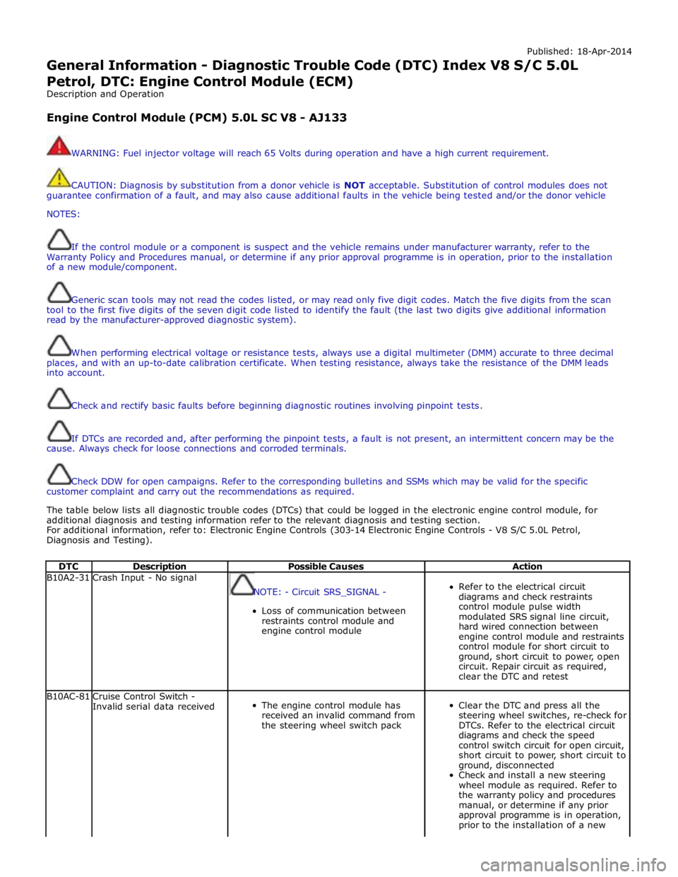
General Information - Diagnostic Trouble Code (DTC) Index V8 S/C 5.0L
Petrol, DTC: Engine Control Module (ECM)
Description and Operation
Engine Control Module (PCM) 5.0L SC V8 - AJ133
WARNING: Fuel injector voltage will reach 65 Volts during operation and have a high current requirement.
CAUTION: Diagnosis by substitution from a donor vehicle is NOT acceptable. Substitution of control modules does not
guarantee confirmation of a fault, and may also cause additional faults in the vehicle being tested and/or the donor vehicle
NOTES:
If the control module or a component is suspect and the vehicle remains under manufacturer warranty, refer to the
Warranty Policy and Procedures manual, or determine if any prior approval programme is in operation, prior to the installation
of a new module/component.
Generic scan tools may not read the codes listed, or may read only five digit codes. Match the five digits from the scan
tool to the first five digits of the seven digit code listed to identify the fault (the last two digits give additional information
read by the manufacturer-approved diagnostic system).
When performing electrical voltage or resistance tests, always use a digital multimeter (DMM) accurate to three decimal
places, and with an up-to-date calibration certificate. When testing resistance, always take the resistance of the DMM leads
into account.
Check and rectify basic faults before beginning diagnostic routines involving pinpoint tests.
If DTCs are recorded and, after performing the pinpoint tests, a fault is not present, an intermittent concern may be the
cause. Always check for loose connections and corroded terminals.
Check DDW for open campaigns. Refer to the corresponding bulletins and SSMs which may be valid for the specific
customer complaint and carry out the recommendations as required.
The table below lists all diagnostic trouble codes (DTCs) that could be logged in the electronic engine control module, for
additional diagnosis and testing information refer to the relevant diagnosis and testing section.
For additional information, refer to: Electronic Engine Controls (303-14 Electronic Engine Controls - V8 S/C 5.0L Petrol,
Diagnosis and Testing).
DTC Description Possible Causes Action B10A2-31 Crash Input - No signal
NOTE: - Circuit SRS_SIGNAL -
Loss of communication between
restraints control module and
engine control module
Refer to the electrical circuit
diagrams and check restraints
control module pulse width
modulated SRS signal line circuit,
hard wired connection between
engine control module and restraints
control module for short circuit to
ground, short circuit to power, open
circuit. Repair circuit as required,
clear the DTC and retest B10AC-81
Cruise Control Switch -
Invalid serial data received
The engine control module has
received an invalid command from
the steering wheel switch pack
Clear the DTC and press all the
steering wheel switches, re-check for
DTCs. Refer to the electrical circuit
diagrams and check the speed
control switch circuit for open circuit,
short circuit to power, short circuit to
ground, disconnected
Check and install a new steering
wheel module as required. Refer to
the warranty policy and procedures
manual, or determine if any prior
approval programme is in operation,
prior to the installation of a new
Page 356 of 3039
Published: 06-Jun-2013
Front Suspension - Front Stabilizer Bar V8 5.0L Petrol/V8 S/C 5.0L Petrol
Removal and Installation
Removal
NOTE: Removal steps in this procedure may contain installation details.
1. Refer to: Battery Disconnect and Connect (414-01 Battery, Mounting and Cables, General Procedures).
2. WARNING: Do not work on or under a vehicle supported only by a jack.
Always support the vehicle on safety stands.
Raise and support the vehicle.
3. Refer to: Air Conditioning (A/C) System Recovery, Evacuation and Charging (412-00 Climate Control System - General Information, General Procedures).
4. Refer to: Radiator Splash Shield (501-02 Front End Body Panels, Removal and Installation).
5. Refer to: Air Deflector (501-02 Front End Body Panels, Removal and Installation).
6. Refer to: Front Wheel Bearing and Wheel Hub - TDV6 3.0L Diesel /V8 5.0L Petrol/V8 S/C 5.0L Petrol (204-01 Front Suspension, Removal and Installation).
7. Refer to: Engine Cover - V8 5.0L Petrol/V8 S/C 5.0L Petrol (501-05 Interior Trim and Ornamentation, Removal and Installation).
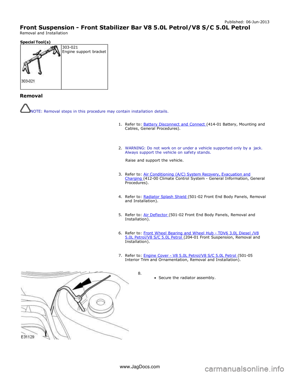
8.
Secure the radiator assembly. 303-021
Engine support bracket Special Tool(s) www.JagDocs.com
Page 361 of 3039

22.
23. Torque:
M6 9 Nm M10 40 Nm
CAUTIONS:
Support the engine on a jack. The angle may need to
be adjusted during this procedure.
Make sure to protect the paintwork.
Special Tool(s): 303-021
24. WARNING: Do not work on or under a vehicle supported only by a
jack. Always support the vehicle on safety stands.
Raise and support the vehicle.
25. www.JagDocs.com
Page 367 of 3039
Suspension, Removal and Installation).
3. Remove the secondary bulkhead panel LH.
For additional information, refer to: Secondary Bulkhead Panel LH - 3.0L NA V6 - AJ27 (501-02 Front End Body Panels, Removal and Installation).
4. Remove the air cleaner.
For additional information, refer to: Air Cleaner (303-12A, Removal and
Installation) /
Air Cleaner (303-12B Intake Air Distribution and Filtering - V6 3.0L Petrol, Removal and Installation) /
Air Cleaner (303-12C, Removal and Installation) /
Air Cleaner LH (303-12D, Removal and Installation).
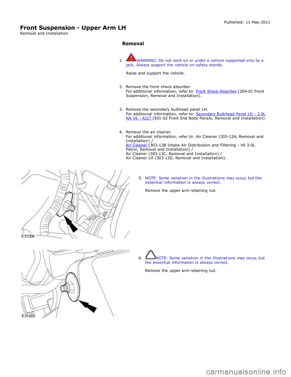
5. NOTE: Some variation in the illustrations may occur, but the
essential information is always correct.
Remove the upper arm retaining nut.
6. NOTE: Some variation in the illustrations may occur, but
the essential information is always correct.
Remove the upper arm retaining nut.
Page 369 of 3039
Suspension, Removal and Installation).
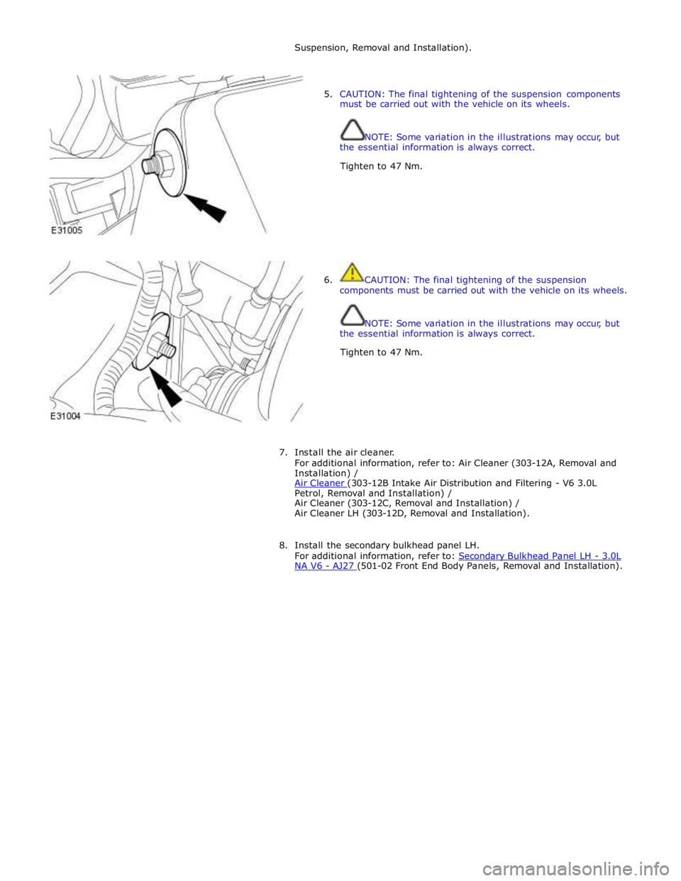
5. CAUTION: The final tightening of the suspension components
must be carried out with the vehicle on its wheels.
NOTE: Some variation in the illustrations may occur, but
the essential information is always correct.
Tighten to 47 Nm.
6. CAUTION: The final tightening of the suspension
components must be carried out with the vehicle on its wheels.
NOTE: Some variation in the illustrations may occur, but
the essential information is always correct.
Tighten to 47 Nm.
7. Install the air cleaner.
For additional information, refer to: Air Cleaner (303-12A, Removal and
Installation) /
Air Cleaner (303-12B Intake Air Distribution and Filtering - V6 3.0L Petrol, Removal and Installation) /
Air Cleaner (303-12C, Removal and Installation) /
Air Cleaner LH (303-12D, Removal and Installation).
8. Install the secondary bulkhead panel LH.
For additional information, refer to: Secondary Bulkhead Panel LH - 3.0L NA V6 - AJ27 (501-02 Front End Body Panels, Removal and Installation).
Page 501 of 3039
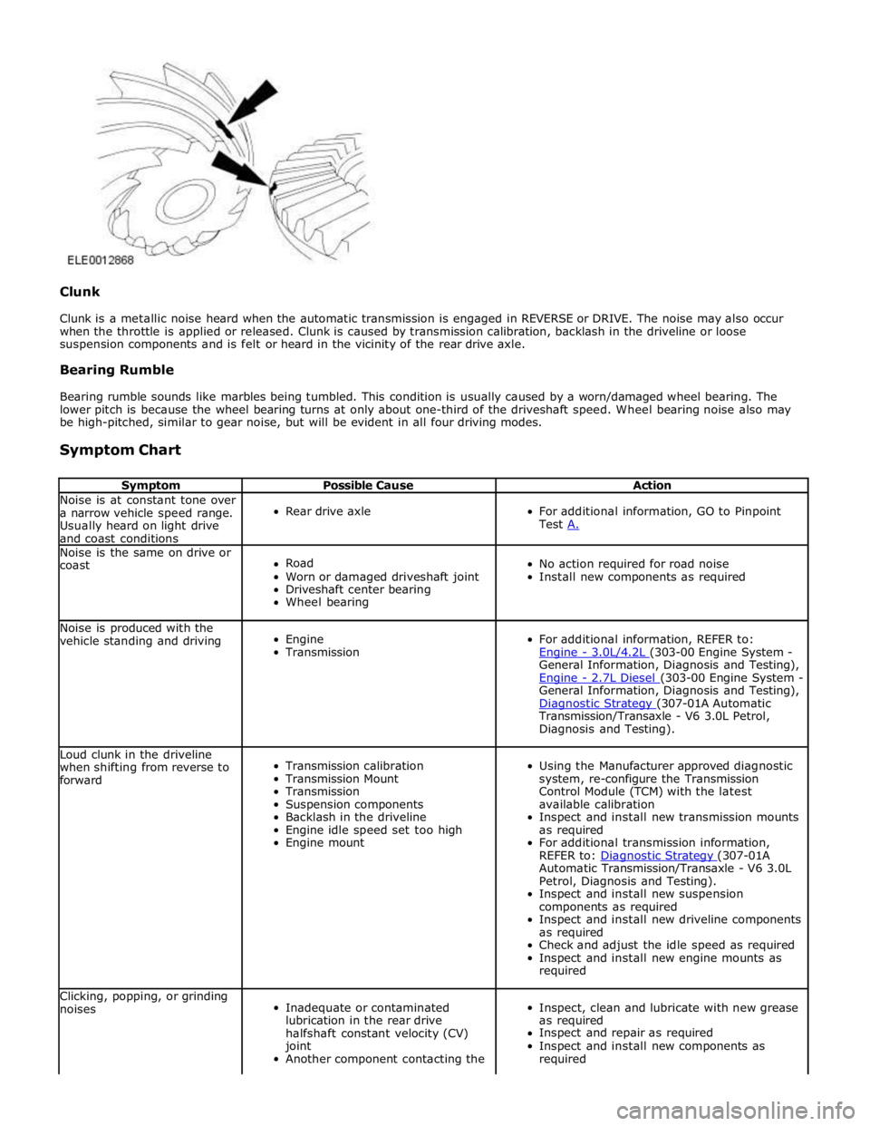
Clunk
Clunk is a metallic noise heard when the automatic transmission is engaged in REVERSE or DRIVE. The noise may also occur
when the throttle is applied or released. Clunk is caused by transmission calibration, backlash in the driveline or loose
suspension components and is felt or heard in the vicinity of the rear drive axle.
Bearing Rumble
Bearing rumble sounds like marbles being tumbled. This condition is usually caused by a worn/damaged wheel bearing. The
lower pitch is because the wheel bearing turns at only about one-third of the driveshaft speed. Wheel bearing noise also may
be high-pitched, similar to gear noise, but will be evident in all four driving modes.
Symptom Chart
Symptom Possible Cause Action Noise is at constant tone over
a narrow vehicle speed range.
Usually heard on light drive
and coast conditions
Rear drive axle
For additional information, GO to Pinpoint
Test A. Noise is the same on drive or
coast
Road
Worn or damaged driveshaft joint
Driveshaft center bearing
Wheel bearing
No action required for road noise
Install new components as required Noise is produced with the
vehicle standing and driving
Engine
Transmission
For additional information, REFER to:
Engine - 3.0L/4.2L (303-00 Engine System - General Information, Diagnosis and Testing),
Engine - 2.7L Diesel (303-00 Engine System - General Information, Diagnosis and Testing),
Diagnostic Strategy (307-01A Automatic Transmission/Transaxle - V6 3.0L Petrol,
Diagnosis and Testing). Loud clunk in the driveline
when shifting from reverse to
forward
Transmission calibration
Transmission Mount
Transmission
Suspension components
Backlash in the driveline
Engine idle speed set too high
Engine mount
Using the Manufacturer approved diagnostic
system, re-configure the Transmission
Control Module (TCM) with the latest
available calibration
Inspect and install new transmission mounts
as required
For additional transmission information,
REFER to: Diagnostic Strategy (307-01A Automatic Transmission/Transaxle - V6 3.0L
Petrol, Diagnosis and Testing).
Inspect and install new suspension
components as required
Inspect and install new driveline components
as required
Check and adjust the idle speed as required
Inspect and install new engine mounts as
required Clicking, popping, or grinding
noises
Inadequate or contaminated
lubrication in the rear drive
halfshaft constant velocity (CV)
joint
Another component contacting the
Inspect, clean and lubricate with new grease
as required
Inspect and repair as required
Inspect and install new components as
required