303 00 JAGUAR XFR 2010 1.G User Guide
[x] Cancel search | Manufacturer: JAGUAR, Model Year: 2010, Model line: XFR, Model: JAGUAR XFR 2010 1.GPages: 3039, PDF Size: 58.49 MB
Page 502 of 3039
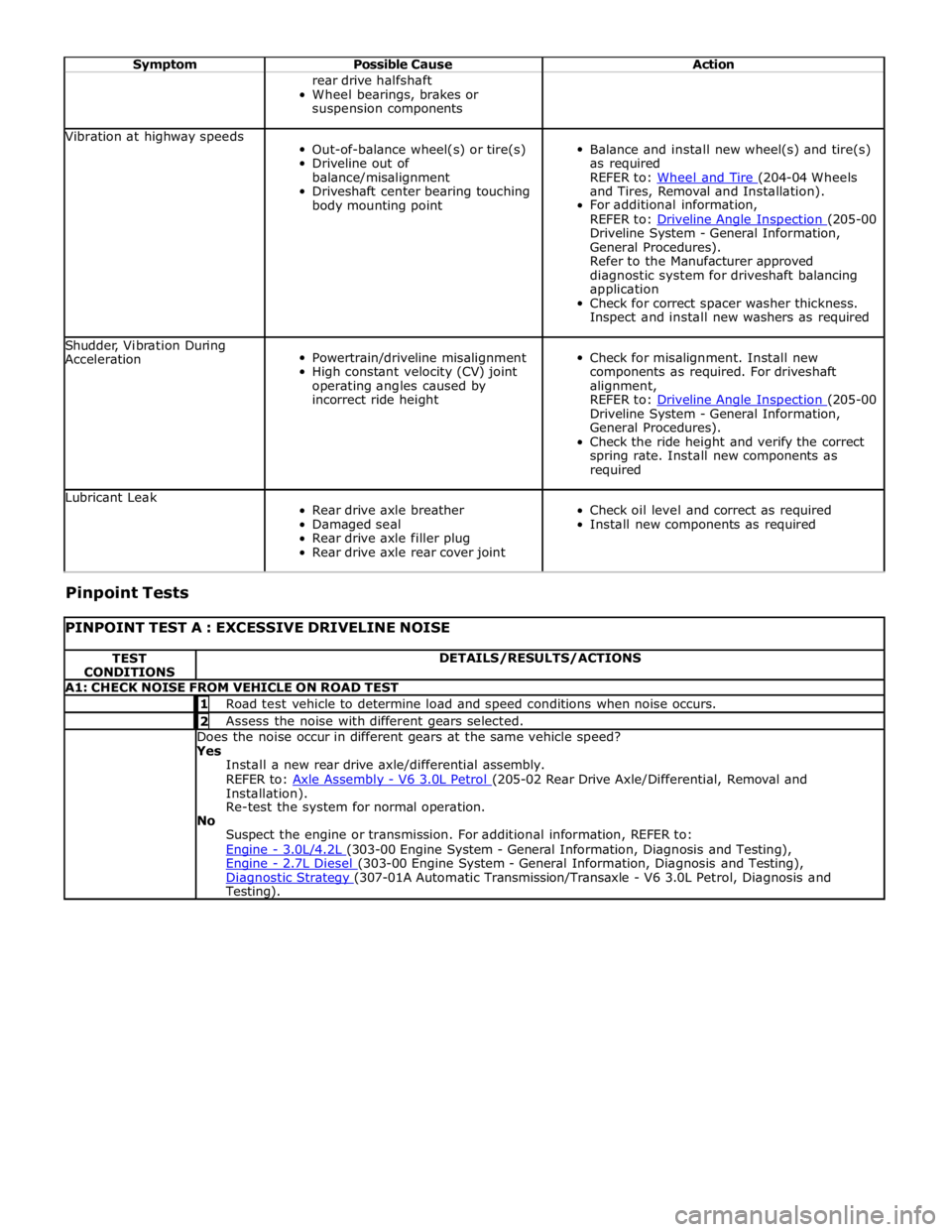
Symptom Possible Cause Action rear drive halfshaft
Wheel bearings, brakes or
suspension components Vibration at highway speeds
Out-of-balance wheel(s) or tire(s)
Driveline out of
balance/misalignment
Driveshaft center bearing touching
body mounting point
Balance and install new wheel(s) and tire(s)
as required
REFER to: Wheel and Tire (204-04 Wheels and Tires, Removal and Installation).
For additional information,
REFER to: Driveline Angle Inspection (205-00 Driveline System - General Information,
General Procedures).
Refer to the Manufacturer approved
diagnostic system for driveshaft balancing
application
Check for correct spacer washer thickness.
Inspect and install new washers as required Shudder, Vibration During
Acceleration
Powertrain/driveline misalignment
High constant velocity (CV) joint
operating angles caused by
incorrect ride height
Check for misalignment. Install new
components as required. For driveshaft
alignment,
REFER to: Driveline Angle Inspection (205-00 Driveline System - General Information,
General Procedures).
Check the ride height and verify the correct
spring rate. Install new components as
required Lubricant Leak
Rear drive axle breather
Damaged seal
Rear drive axle filler plug
Rear drive axle rear cover joint
Check oil level and correct as required
Install new components as required Pinpoint Tests
PINPOINT TEST A : EXCESSIVE DRIVELINE NOISE TEST
CONDITIONS DETAILS/RESULTS/ACTIONS A1: CHECK NOISE FROM VEHICLE ON ROAD TEST 1 Road test vehicle to determine load and speed conditions when noise occurs. 2 Assess the noise with different gears selected. Does the noise occur in different gears at the same vehicle speed? Yes
Install a new rear drive axle/differential assembly.
REFER to: Axle Assembly - V6 3.0L Petrol (205-02 Rear Drive Axle/Differential, Removal and Installation).
Re-test the system for normal operation.
No
Suspect the engine or transmission. For additional information, REFER to:
Engine - 3.0L/4.2L (303-00 Engine System - General Information, Diagnosis and Testing), Engine - 2.7L Diesel (303-00 Engine System - General Information, Diagnosis and Testing), Diagnostic Strategy (307-01A Automatic Transmission/Transaxle - V6 3.0L Petrol, Diagnosis and Testing).
Page 547 of 3039
Published: 11-May-2011
Rear Drive Axle/Differential - Differential Front Bushing TDV6 3.0L Diesel /V8 5.0L Petrol/V8 S/C 5.0L Petrol
Removal and Installation
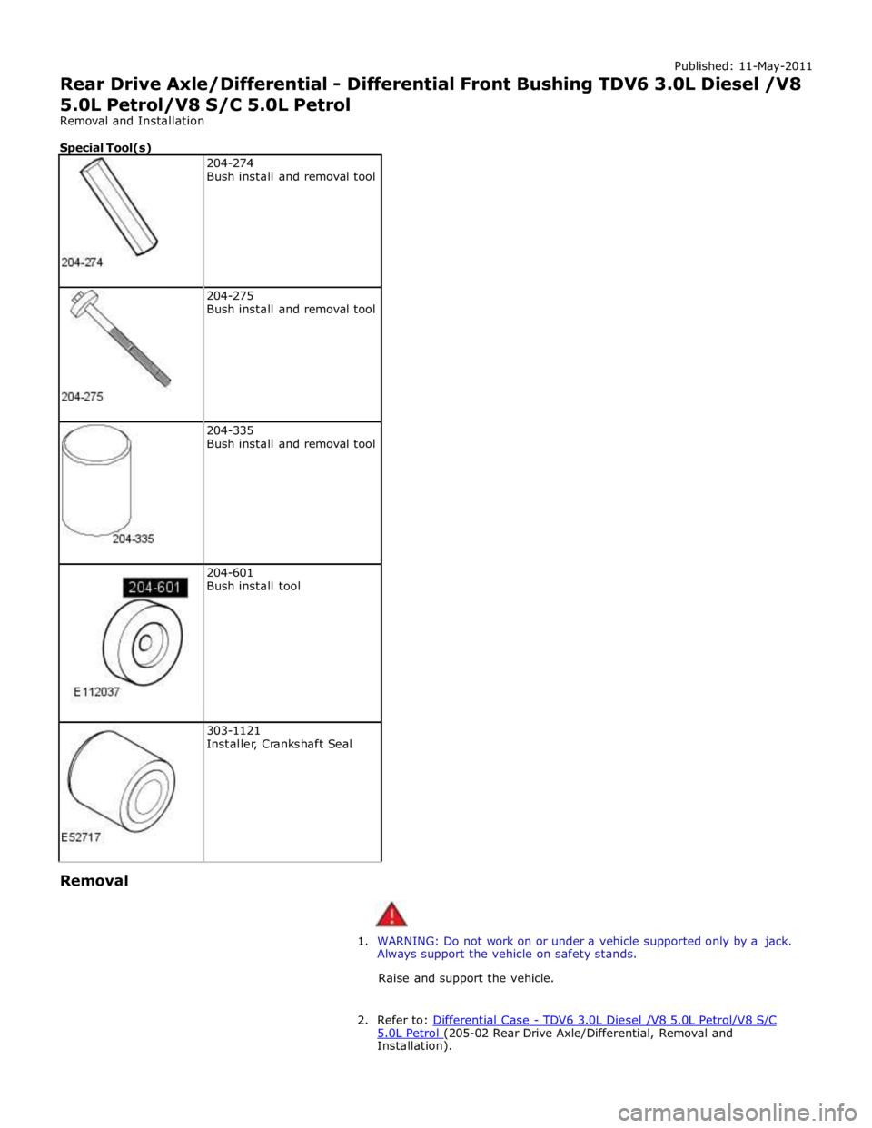
Special Tool(s)
204-274
Bush install and removal tool
204-275
Bush install and removal tool
204-335
Bush install and removal tool
204-601
Bush install tool
303-1121
Installer, Crankshaft Seal Removal
1. WARNING: Do not work on or under a vehicle supported only by a jack.
Always support the vehicle on safety stands.
Raise and support the vehicle.
2. Refer to: Differential Case - TDV6 3.0L Diesel /V8 5.0L Petrol/V8 S/C 5.0L Petrol (205-02 Rear Drive Axle/Differential, Removal and Installation).
Page 548 of 3039
Installation
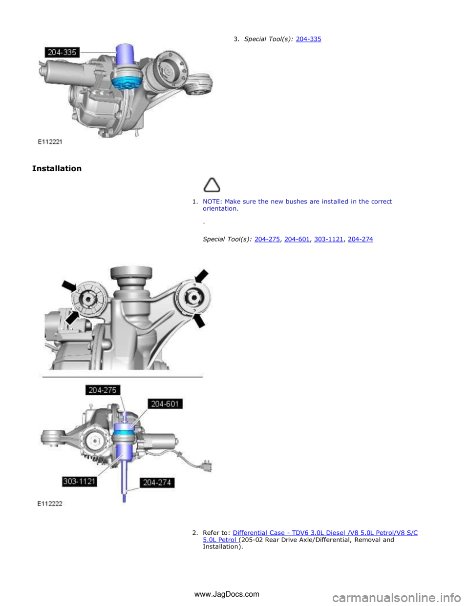
3. Special Tool(s): 204-335
1. NOTE: Make sure the new bushes are installed in the correct
orientation.
.
Special Tool(s): 204-275, 204-601, 303-1121, 204-274
2. Refer to: Differential Case - TDV6 3.0L Diesel /V8 5.0L Petrol/V8 S/C 5.0L Petrol (205-02 Rear Drive Axle/Differential, Removal and Installation). www.JagDocs.com
Page 638 of 3039
Published: 11-May-2011
Rear Disc Brake - TDV6 3.0L Diesel /V8 5.0L Petrol/V8 S/C 5.0L Petrol - Brake
Pads Vehicles With: High Performance Brakes
Removal and Installation
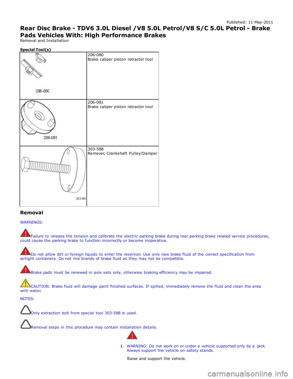
Special Tool(s)
206-080
Brake caliper piston retractor tool
206-081
Brake caliper piston retractor tool
303-588
Remover, Crankshaft Pulley/Damper Removal
WARNINGS:
Failure to release the tension and calibrate the electric parking brake during rear parking brake related service procedures,
could cause the parking brake to function incorrectly or become inoperative.
Do not allow dirt or foreign liquids to enter the reservoir. Use only new brake fluid of the correct specification from
airtight containers. Do not mix brands of brake fluid as they may not be compatible.
Brake pads must be renewed in axle sets only, otherwise braking efficiency may be impaired.
CAUTION: Brake fluid will damage paint finished surfaces. If spilled, immediately remove the fluid and clean the area
with water.
NOTES:
Only extraction bolt from special tool 303-588 is used.
Removal steps in this procedure may contain installation details.
1. WARNING: Do not work on or under a vehicle supported only by a jack.
Always support the vehicle on safety stands.
Raise and support the vehicle.
Page 642 of 3039

10.
11. NOTE: Left-hand shown, right-hand similar.
Special Tool(s): 303-588 Special Tool(s): 206-080 Special Tool(s): 206-081 Using the special tools, fully retract the brake
caliper piston.
12.
Repeat the above procedure on the opposite side.
Installation
1. NOTE: The brake pad wear sensor retaining tang must be
installed to the sensor prior to installation to the brake
pad.
2. To install, reverse the removal procedure.
3. Repeat the above procedure on the opposite side.
Page 688 of 3039

Published: 08-Oct-2012
Power Brake Actuation - Brake Vacuum Pump V8 5.0L Petrol/V8 S/C 5.0L
Petrol
Removal and Installation
Removal
CAUTION: Make sure that all openings are sealed. Use new blanking caps.
NOTE: Removal steps in this procedure may contain installation details.
1. WARNING: Make sure to support the vehicle with axle stands.
Raise and support the vehicle.
2. Refer to: Engine Oil Draining and Filling (303-01, General Procedures).
3.
4. CAUTION: Be prepared to collect escaping oil.
Torque: 12 Nm
Page 759 of 3039
Published: 11-May-2011
Power Steering - Power Steering Pump V8 5.0L Petrol/V8 S/C 5.0L Petrol
Removal and Installation
Removal
NOTES:
Removal steps in this procedure may contain installation details.
Some variation in the illustrations may occur, but the essential information is always correct.
1. Refer to: Battery Disconnect and Connect (414-01 Battery, Mounting and Cables, General Procedures).
2. WARNING: Do not work on or under a vehicle supported only by a jack.
Always support the vehicle on safety stands.
Raise and support the vehicle.
3. Refer to: Power Steering System Bleeding (211-00 Steering System - General Information, General Procedures).
4. Refer to: Air Cleaner Outlet Pipe LH (303-12D Intake Air Distribution and Filtering - V8 S/C 5.0L Petrol, Removal and Installation).
5. Refer to: Air Cleaner LH (303-12D Intake Air Distribution and Filtering - V8 S/C 5.0L Petrol, Removal and Installation).
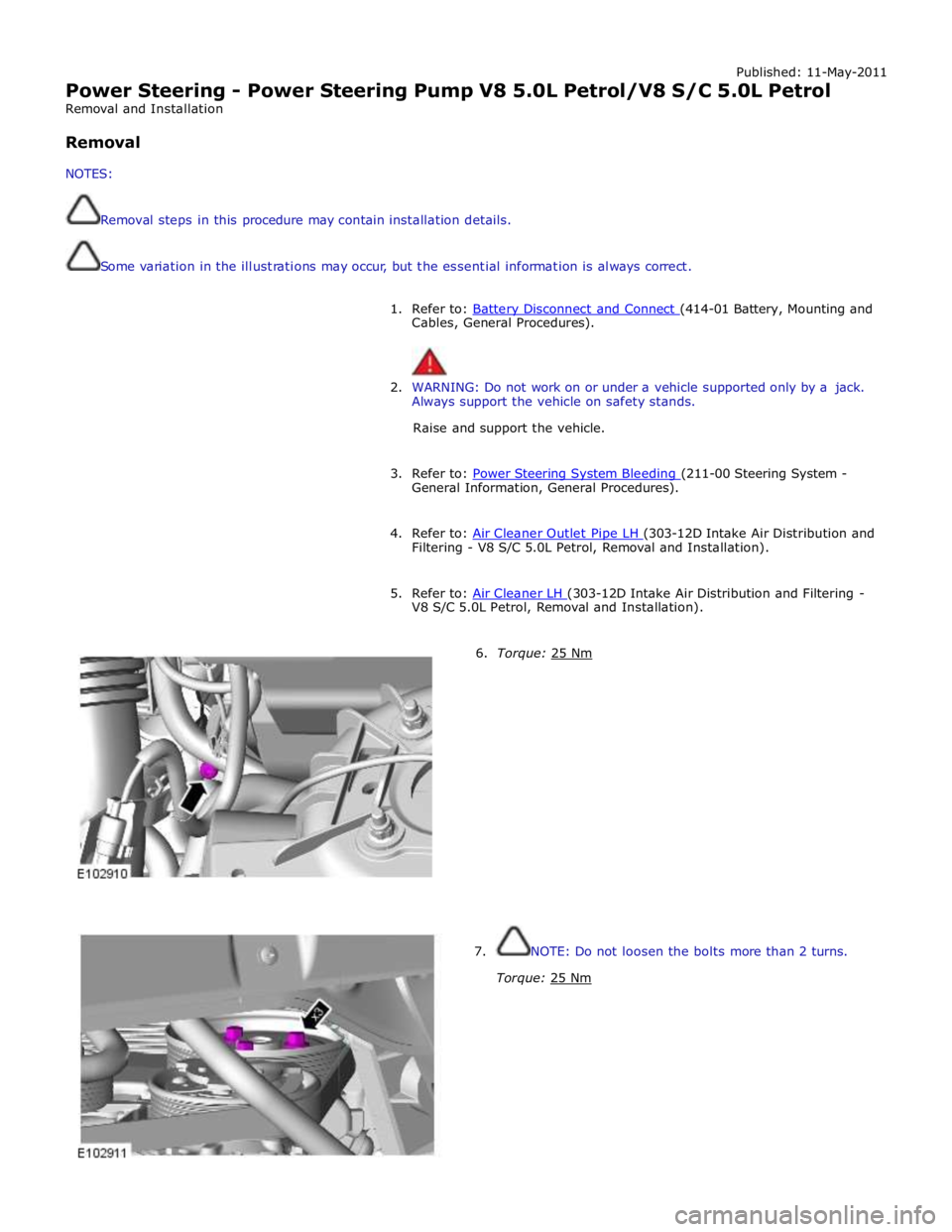
6. Torque: 25 Nm 7. NOTE: Do not loosen the bolts more than 2 turns.
Torque: 25 Nm
Page 811 of 3039
Engine System - General Information - Engine 5.0L
Diagnosis and Testing
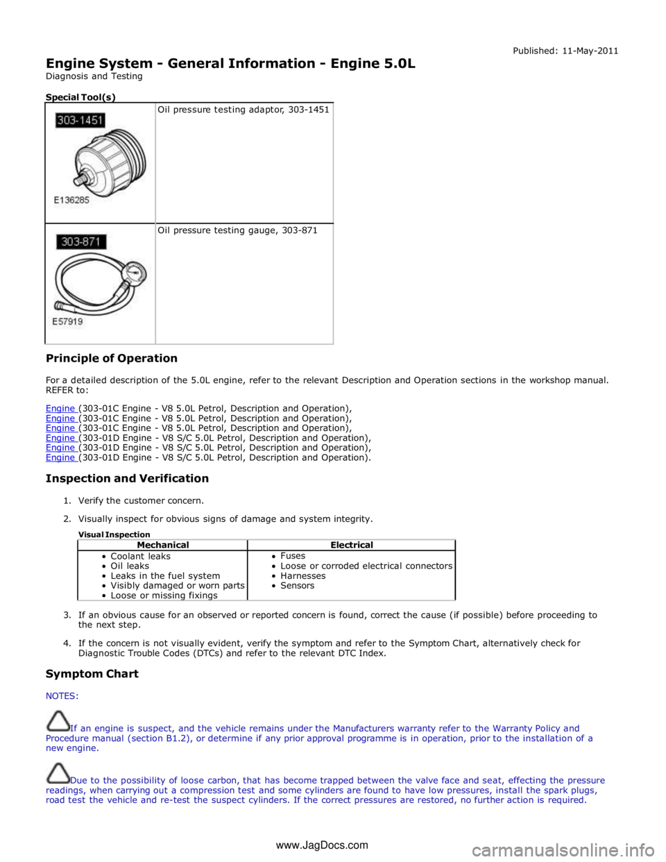
Special Tool(s)
Oil pressure testing adaptor, 303-1451
Oil pressure testing gauge, 303-871 Principle of Operation Published: 11-May-2011
For a detailed description of the 5.0L engine, refer to the relevant Description and Operation sections in the workshop manual.
REFER to:
Engine (303-01C Engine - V8 5.0L Petrol, Description and Operation), Engine (303-01C Engine - V8 5.0L Petrol, Description and Operation), Engine (303-01C Engine - V8 5.0L Petrol, Description and Operation), Engine (303-01D Engine - V8 S/C 5.0L Petrol, Description and Operation), Engine (303-01D Engine - V8 S/C 5.0L Petrol, Description and Operation), Engine (303-01D Engine - V8 S/C 5.0L Petrol, Description and Operation).
Inspection and Verification
1. Verify the customer concern.
2. Visually inspect for obvious signs of damage and system integrity.
Visual Inspection
Mechanical Electrical Coolant leaks
Oil leaks
Leaks in the fuel system
Visibly damaged or worn parts
Loose or missing fixings Fuses
Loose or corroded electrical connectors
Harnesses
Sensors
3. If an obvious cause for an observed or reported concern is found, correct the cause (if possible) before proceeding to
the next step.
4. If the concern is not visually evident, verify the symptom and refer to the Symptom Chart, alternatively check for
Diagnostic Trouble Codes (DTCs) and refer to the relevant DTC Index.
Symptom Chart
NOTES:
If an engine is suspect, and the vehicle remains under the Manufacturers warranty refer to the Warranty Policy and
Procedure manual (section B1.2), or determine if any prior approval programme is in operation, prior to the installation of a
new engine.
Due to the possibility of loose carbon, that has become trapped between the valve face and seat, effecting the pressure
readings, when carrying out a compression test and some cylinders are found to have low pressures, install the spark plugs,
road test the vehicle and re-test the suspect cylinders. If the correct pressures are restored, no further action is required. www.JagDocs.com
Page 812 of 3039
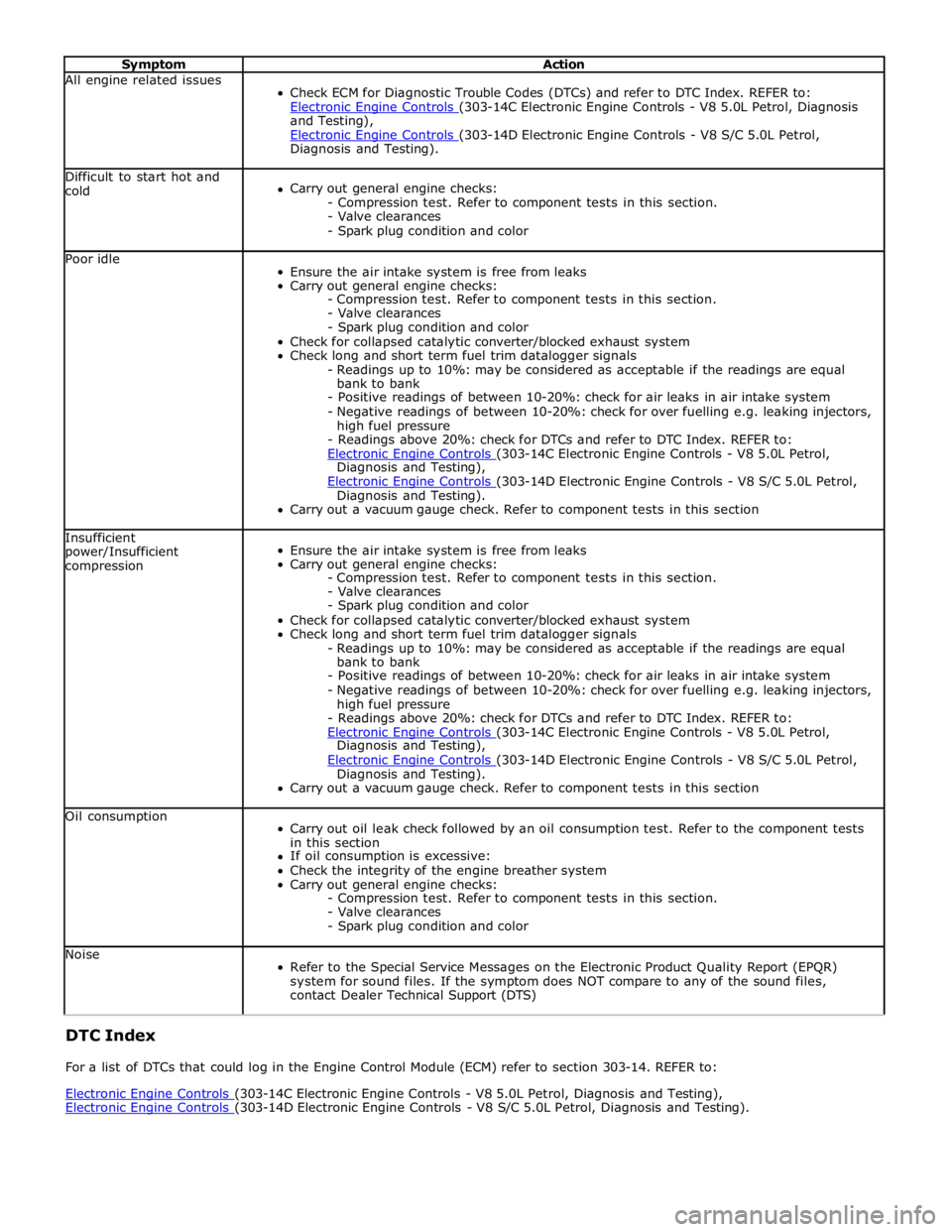
Symptom Action All engine related issues
Check ECM for Diagnostic Trouble Codes (DTCs) and refer to DTC Index. REFER to:
Electronic Engine Controls (303-14C Electronic Engine Controls - V8 5.0L Petrol, Diagnosis and Testing),
Electronic Engine Controls (303-14D Electronic Engine Controls - V8 S/C 5.0L Petrol, Diagnosis and Testing). Difficult to start hot and
cold
Carry out general engine checks:
- Compression test. Refer to component tests in this section.
- Valve clearances
- Spark plug condition and color Poor idle
Ensure the air intake system is free from leaks
Carry out general engine checks:
- Compression test. Refer to component tests in this section.
- Valve clearances
- Spark plug condition and color
Check for collapsed catalytic converter/blocked exhaust system
Check long and short term fuel trim datalogger signals
- Readings up to 10%: may be considered as acceptable if the readings are equal
bank to bank
- Positive readings of between 10-20%: check for air leaks in air intake system
- Negative readings of between 10-20%: check for over fuelling e.g. leaking injectors,
high fuel pressure
- Readings above 20%: check for DTCs and refer to DTC Index. REFER to:
Electronic Engine Controls (303-14C Electronic Engine Controls - V8 5.0L Petrol, Diagnosis and Testing),
Electronic Engine Controls (303-14D Electronic Engine Controls - V8 S/C 5.0L Petrol, Diagnosis and Testing).
Carry out a vacuum gauge check. Refer to component tests in this section Insufficient
power/Insufficient
compression
Ensure the air intake system is free from leaks
Carry out general engine checks:
- Compression test. Refer to component tests in this section.
- Valve clearances
- Spark plug condition and color
Check for collapsed catalytic converter/blocked exhaust system
Check long and short term fuel trim datalogger signals
- Readings up to 10%: may be considered as acceptable if the readings are equal
bank to bank
- Positive readings of between 10-20%: check for air leaks in air intake system
- Negative readings of between 10-20%: check for over fuelling e.g. leaking injectors,
high fuel pressure
- Readings above 20%: check for DTCs and refer to DTC Index. REFER to:
Electronic Engine Controls (303-14C Electronic Engine Controls - V8 5.0L Petrol, Diagnosis and Testing),
Electronic Engine Controls (303-14D Electronic Engine Controls - V8 S/C 5.0L Petrol, Diagnosis and Testing).
Carry out a vacuum gauge check. Refer to component tests in this section Oil consumption
Carry out oil leak check followed by an oil consumption test. Refer to the component tests
in this section
If oil consumption is excessive:
Check the integrity of the engine breather system
Carry out general engine checks:
- Compression test. Refer to component tests in this section.
- Valve clearances
- Spark plug condition and color Noise
Refer to the Special Service Messages on the Electronic Product Quality Report (EPQR)
system for sound files. If the symptom does NOT compare to any of the sound files,
contact Dealer Technical Support (DTS) DTC Index
For a list of DTCs that could log in the Engine Control Module (ECM) refer to section 303-14. REFER to:
Electronic Engine Controls (303-14C Electronic Engine Controls - V8 5.0L Petrol, Diagnosis and Testing), Electronic Engine Controls (303-14D Electronic Engine Controls - V8 S/C 5.0L Petrol, Diagnosis and Testing).
Page 816 of 3039
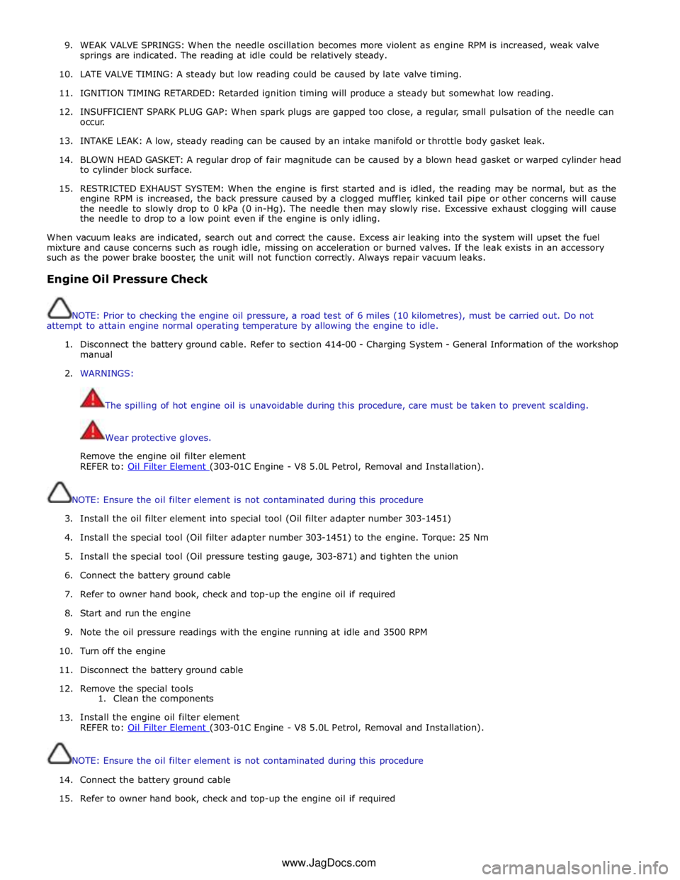
9. WEAK VALVE SPRINGS: When the needle oscillation becomes more violent as engine RPM is increased, weak valve
springs are indicated. The reading at idle could be relatively steady.
10. LATE VALVE TIMING: A steady but low reading could be caused by late valve timing.
11.
IGNITION TIMING RETARDED: Retarded ignition timing will produce a steady but somewhat low reading.
12.
INSUFFICIENT SPARK PLUG GAP: When spark plugs are gapped too close, a regular, small pulsation of the needle can
occur.
13. INTAKE LEAK: A low, steady reading can be caused by an intake manifold or throttle body gasket leak.
14.
BLOWN HEAD GASKET: A regular drop of fair magnitude can be caused by a blown head gasket or warped cylinder head
to cylinder block surface.
15.
RESTRICTED EXHAUST SYSTEM: When the engine is first started and is idled, the reading may be normal, but as the
engine RPM is increased, the back pressure caused by a clogged muffler, kinked tail pipe or other concerns will cause
the needle to slowly drop to 0 kPa (0 in-Hg). The needle then may slowly rise. Excessive exhaust clogging will cause
the needle to drop to a low point even if the engine is only idling.
When vacuum leaks are indicated, search out and correct the cause. Excess air leaking into the system will upset the fuel
mixture and cause concerns such as rough idle, missing on acceleration or burned valves. If the leak exists in an accessory
such as the power brake booster, the unit will not function correctly. Always repair vacuum leaks.
Engine Oil Pressure Check
NOTE: Prior to checking the engine oil pressure, a road test of 6 miles (10 kilometres), must be carried out. Do not
attempt to attain engine normal operating temperature by allowing the engine to idle.
1. Disconnect the battery ground cable. Refer to section 414-00 - Charging System - General Information of the workshop
manual
2. WARNINGS:
The spilling of hot engine oil is unavoidable during this procedure, care must be taken to prevent scalding.
Wear protective gloves.
Remove the engine oil filter element
REFER to: Oil Filter Element (303-01C Engine - V8 5.0L Petrol, Removal and Installation).
NOTE: Ensure the oil filter element is not contaminated during this procedure
3. Install the oil filter element into special tool (Oil filter adapter number 303-1451)
4. Install the special tool (Oil filter adapter number 303-1451) to the engine. Torque: 25 Nm
5. Install the special tool (Oil pressure testing gauge, 303-871) and tighten the union
6. Connect the battery ground cable
7. Refer to owner hand book, check and top-up the engine oil if required
8. Start and run the engine
9. Note the oil pressure readings with the engine running at idle and 3500 RPM
10.
Turn off the engine
11.
Disconnect the battery ground cable
12. Remove the special tools
1. Clean the components
13.
Install the engine oil filter element
REFER to: Oil Filter Element (303-01C Engine - V8 5.0L Petrol, Removal and Installation).
NOTE: Ensure the oil filter element is not contaminated during this procedure
14.
Connect the battery ground cable
15. Refer to owner hand book, check and top-up the engine oil if required
www.JagDocs.com