Module control functions JAGUAR XFR 2010 1.G Workshop Manual
[x] Cancel search | Manufacturer: JAGUAR, Model Year: 2010, Model line: XFR, Model: JAGUAR XFR 2010 1.GPages: 3039, PDF Size: 58.49 MB
Page 495 of 3039
Published: 11-May-2011
Ride and Handling Optimization - Ride and Handling Optimization - System
Operation and Component Description
Description and Operation
JAGUARDRIVE CONTROL OPERATION
Engine Management System System Operation
The Engine Management System (EMS) varies the accelerator pedal maps to change the amount of torque per percentage of
pedal travel. The EMS can also change the accelerator pedal response to control the allowed torque change relative to the
speed of pedal travel.
Each driving mode uses a combination of operating parameters for each sub-system. Changing between driving modes initiates
a different set of operating characteristics, which will be noticeable to the driver. The driver will notice differences in engine
response when, for example, the accelerator pedal is held in a constant position and the driving mode is changed from Winter
to Dynamic, the driver will notice the torque and engine speed increase. Similarly, if the mode is changed from Normal or
Dynamic to Winter the driver will notice a reduction in torque and engine speed.
NOTE: The change in torque and engine speed can take approximately 30 seconds and care must be taken not to confuse
the JaguarDrive Control system operation with an EMS fault.
Transmission Control
The TCM (transmission control module) changes the shift maps for the JaguarDrive Control mode selected. This changes the
shift points providing early or late upshifts and downshifts. For example, on slippery surfaces in Winter mode the transmission
will select 2nd gear for starting from a standstill on a flat surface to minimize wheel slip.
Anti-lock Braking System Control
The ABS (anti-lock brake system) module controls several vehicle functions and adjusts the operating parameters of these
functions to optimize the selected JaguarDrive Control mode. Traction control uses different slip/acceleration thresholds to
improve traction and vehicle composure. For example, the system sensitivity is increased on slippery surfaces to reduce wheel
spin.
If TracDSC is selected or DSC is switched off, then subsequently the JaguarDrive Control mode is changed, DSC is automatically
switched back on (or to TracDSC for Dynamic mode).
The stability control uses different threshold values for the selected mode, reducing the requirement for the driver to change
the DSC system mode for optimum performance in various driving scenarios.
Incorrect Mode Usage
Selection of an inappropriate mode is discouraged in the following ways:
The active mode icon is continually displayed in the instrument cluster message center
In any special mode, when the ignition has been in the off position continuously for more than 6 hours, the JaguarDrive
Control system defaults to the special modes off (DSC on).
Selection of an inappropriate mode for the conditions will not endanger the driver or immediately cause damage to the vehicle.
Continued use of an inappropriate mode may reduce the life of some components. The driver may notice a different vehicle
response, with the engine and transmission responses being different than in the special modes off.
Driver Information
The instrument cluster contains a message center, which displays vehicle information to the driver. The message center
contains the JaguarDrive Control mode icons, which display the currently selected mode. If no symbol is displayed, no special
mode is selected and the system is in special modes off.
Any required changes to the subsystems are also passed to the driver in the form of warning illumination in the instrument
cluster or appropriate messages in the message center, DSC off for example.
In Dynamic mode when the transmission is in manual mode, the gear information is displayed in amber when the appropriate
engine speed is reached for optimum sporty change point.
DIAGNOSTICS
JaguarDrive Control relies on the correct functionality of the sub-systems. If one of the sub-systems develops a fault, the
JaguarDrive Control system will not function, even though the fault is not in the JaguarDrive Control system.
The JaguarDrive Selector module and rotary control should only be investigated if there are no apparent faults in any of the
sub-systems. If a fault in a sub-system is subsequently corrected, the JaguarDrive Control system will function normally after
an ignition on and off cycle.
Page 692 of 3039
Published: 11-May-2011
Anti-Lock Control - Stability Assist - Anti-Lock Control - Stability Assist - Overview
Description and Operation
Overview
The ABS (anti-lock brake system) and DSC (dynamic stability control) system features a Bosch modulator, which is an
integrated four-channel HCU (hydraulic control unit) and ABS module. The unit is located in the rear of the engine compartment on the passenger side, and is installed in the brake hydraulic circuit between the brake master cylinder and the four brake
calipers.
The ABS module is connected to the high speed CAN (controller area network) bus, and actively interacts with other vehicle system control modules and associated sensors to receive and transmit current vehicle operating information.
When required, the ABS module will actively intervene and operate the HCU during braking or vehicle maneuvers to correct the vehicle attitude, stability, traction or speed. During incidents of vehicle correction, the ABS module may also request the ECM (engine control module) to control engine power in order to further stabilize and correct the vehicle.
To provide full system functionality, the ABS and DSC system comprise the following components: DSC switch.
Four wheel speed sensors.
Steering angle sensor.
Yaw rate and lateral acceleration sensor.
Stoplamp switch.
Instrument cluster indicator lamps.
Integrated ABS module and HCU. Brake booster vacuum sensor (3.0L vehicles only).
Two variants of ABS module are available, Bosch ESP®8.1 and Bosch ESP®plus8.1. The Bosch ESP®plus8.1 system is fitted to vehicles with ACC (adaptive cruise control) and incorporates a new feature to Jaguar known as 'electronic brake prefill'.
Electronic brake prefill, senses any rapid throttle lift off, activating a small brake hydraulic pressure build-up of approximately 3
to 5 bar (43.5 to 72.5 lbf/in²) in anticipation of the brakes being applied. This application produces a quicker brake pedal
response and consequently slightly shorter stopping distances. When the ECM detects rapid throttle lift off it signals the ABS module which controls the HCU to apply a low brake pressure to assist in a quicker brake application.
NOTE: All vehicles with ACC are supported by the Bosch ESP®plus8.1 system.
The ABS provides the following brake functions that are designed to assist the vehicle or aid the driver: ABS. DSC, including Trac DSC.
CBC (corner brake control).
EBD (electronic brake force distribution).
ETC (electronic traction control).
EBA (emergency brake assist).
EDC (engine drag-torque control).
Understeer control.
Electronic brake prefill (vehicles with ACC only).
Brake vacuum assist (3.0L vehicles only).
All the brake functions listed are automatically active when the ignition is in power mode and the engine is running. The DSC
system can be selected to off using the DSC switch.
WARNING: Although the vehicle is fitted with DSC, it remains the drivers responsibility to drive safely according to the
prevailing conditions.
Page 702 of 3039
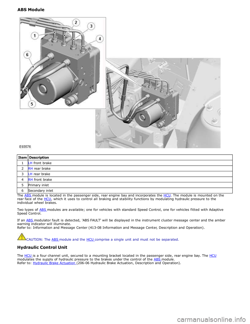
ABS Module
Item Description 1 LH front brake 2 RH rear brake 3 LH rear brake 4 RH front brake 5 Primary inlet 6 Secondary inlet The ABS module is located in the passenger side, rear engine bay and incorporates the HCU. The module is mounted on the rear face of the HCU, which it uses to control all braking and stability functions by modulating hydraulic pressure to the individual wheel brakes.
Two types of ABS modules are available; one for vehicles with standard Speed Control, one for vehicles fitted with Adaptive Speed Control.
If an ABS modulator fault is detected, 'ABS FAULT' will be displayed in the instrument cluster message center and the amber warning indicator will illuminate.
Refer to: Information and Message Center (413-08 Information and Message Center, Description and Operation).
CAUTION: The ABS module and the HCU comprise a single unit and must not be separated.
Hydraulic Control Unit
The HCU is a four channel unit, secured to a mounting bracket located in the passenger side, rear engine bay. The HCU modulates the supply of hydraulic pressure to the brakes under the control of the ABS module. Refer to: Hydraulic Brake Actuation (206-06 Hydraulic Brake Actuation, Description and Operation).
Page 800 of 3039
path is completed and a signal voltage is returned to the instrument cluster via a resistor. The returned reference voltage is
detected by the instrument cluster and performs the requested trip function.
RIGHT HAND MULTIFUNCTION SWITCH
The instrument cluster outputs 4 separate reference voltages to the following switch functions:
Wash/wipe switch
Intermittent wipe switch
Master wiper switch
Flick wipe switch.
Wash/Wipe Switch
The reference voltage is supplied to one of two resistors connected in parallel. When the switch is not being operated the
current flows through one resistor and the returned signal voltage is monitored by the instrument cluster. When the wash/wipe
switch is operated, a connection is made and the current flows through the second resistor. The change in signal voltage is
detected by the instrument cluster which outputs a message on the medium speed CAN bus to the CJB to activate the wash/wipe function.
Intermittent Delay/Auto Wipe Switch
The reference voltage is supplied to the switch and can pass through up to 7 resistors, connected in series, for intermittent
delay selections and the auto wipe function.
When the rotary switch is in the auto position the reference voltage flows through 1 resistor. The returned signal voltage is
detected by the instrument cluster which determines auto wipe is selected. The instrument cluster outputs a message on the
medium speed CAN bus to the CJB to activate the auto wipe function.
With the rotary switch in one of the intermittent positions, the reference voltage is routed through up to 7 of the resistors
depending on the delay period selected. The returned signal voltage is detected by the instrument cluster which determines
selected delay period. The instrument cluster outputs a message on the medium speed CAN bus to the CJB to activate the selected intermittent wipe function.
NOTE: The delay period for the intermittent selections can vary according to vehicle speed.
Master Wiper Switch
The reference voltage supplied from the instrument cluster to the master wiper switch. The voltage can pass through up to 4
resistors connected in series.
When the switch is in the off position, the reference voltage passes through 4 resistors and the returned voltage is monitored
by the instrument cluster. The instrument cluster outputs a message on the medium speed CAN bus to the CJB that no wiper selections have been requested.
With the switch in the intermittent, slow wipe or fast wipe position, the reference voltage passes through 3, 2 or 1 resistors
respectively. The returned signal voltage is detected by the instrument cluster which determines selected delay period. The
instrument cluster outputs a message on the medium speed CAN bus to the CJB to activate the selected wipe function. Flick Wipe Switch
The reference voltage is supplied to one of two resistors connected in parallel. When the switch is not being operated the
current flows through one resistor and the returned signal voltage is monitored by the instrument cluster. When the flick wipe
switch is operated, a connection is made and the current flows through the second resistor. The change in signal voltage is
detected by the instrument cluster which outputs a message on the medium speed CAN bus to the CJB to activate the flick wipe function.
STEERING COLUMN ADJUSTMENT SWITCH
The instrument cluster supplies 2 reference voltages to the column adjustment switch.
The first reference voltage is supplied to the joystick switch. When the switch is moved to one of its 4 positions, the switch
contact is completed and the reference voltage is passed through one of 4 different resistors with different values. The
returned signal voltage is measured by the instrument cluster which determines the selected column adjust request. The
instrument cluster outputs a supply to the steering column adjustment motor and energizes the applicable clutch solenoid to
move the column to the desired position.
The second reference voltage is supplied to the auto/manual selection of the switch. When the switch is in the auto position,
the reference voltage passes directly through the switch contacts and is measured by the instrument cluster. The instrument
cluster outputs a message on the medium speed CAN bus to the driver seat module which responds with the recorded memory position setting. The instrument cluster then activates the column adjustment motor and clutch solenoids to move the column
to the memorized position. When the switch is in the manual position the reference circuit is broken. The instrument cluster
detects the broken circuit and allows manual operation of the column adjustment switch to move the column.
HEATED STEERING WHEEL
The heated steering wheel receives a battery power supply via the CJB. The heated steering wheel is controlled by the driver using a selection on the TSD. When the driver selects the heated steering wheel to be active, the request is passed from the
TSD on the MOST ring to the information and entertainment module. The information and entertainment module converts the
Page 801 of 3039
battery power supply to be passed via the slip ring assembly in the steering wheel to the heated steering wheel control
module. The steering wheel module supplies power to the steering wheel heater element and also monitors the temperature
via a NTC (negative temperature coefficient) temperature sensor incorporated into the heater element. The control module
varies the power supply to the element to maintain the steering wheel rim at the optimum temperature.
Component Description STEERING COLUMN MULTIFUNCTION SWITCHES
The steering column multifunction switches are situated on the steering column and consists of the wiper switch, the turn
signal indicator/lighting switch and the trip computer switch.
The steering column adjustment switch is located in the steering column lower shroud on the LH side. The switch is a 4 position 'joystick' which controls reach and rake adjustment.
Steering wheel mounted switches on the LH side of the driver's airbag, control the audio and telephone functions. Switches on the RH side of the driver's airbag, control the speed control functions. For additional information, refer to:
Audio System (415-01A Information and Entertainment System, Description and Operation), Speed Control (310-03A, Description and Operation),
Speed Control (310-03B, Description and Operation),
Speed Control (310-03C, Description and Operation).
Two transmission paddle switches are located at the rear of the steering wheel.
Refer to: External Controls (307-05, Description and Operation).
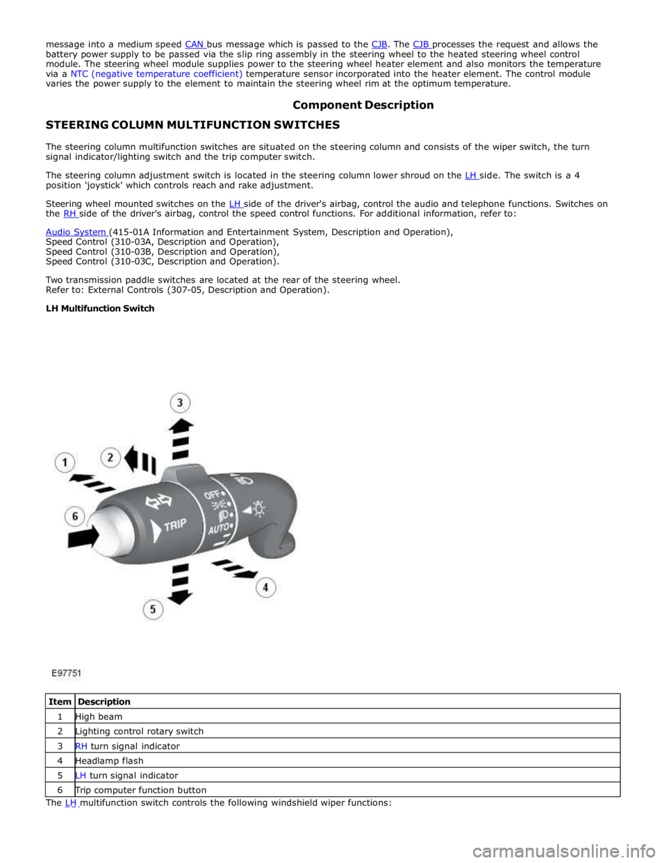
LH Multifunction Switch
Item Description 1 High beam 2 Lighting control rotary switch 3 RH turn signal indicator 4 Headlamp flash 5 LH turn signal indicator 6 Trip computer function button The LH multifunction switch controls the following windshield wiper functions:
Page 1367 of 3039
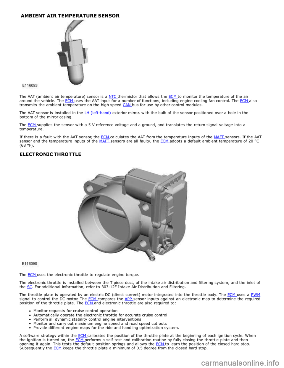
around the vehicle. The ECM uses the AAT input for a number of functions, including engine cooling fan control. The ECM also transmits the ambient temperature on the high speed CAN bus for use by other control modules.
The AAT sensor is installed in the LH (left-hand) exterior mirror, with the bulb of the sensor positioned over a hole in the
bottom of the mirror casing.
The ECM supplies the sensor with a 5 V reference voltage and a ground, and translates the return signal voltage into a temperature.
If there is a fault with the AAT sensor, the ECM calculates the AAT from the temperature inputs of the MAFT sensors. If the AAT sensor and the temperature inputs of the MAFT sensors are all faulty, the ECM adopts a default ambient temperature of 20 °C (68 °F).
ELECTRONIC THROTTLE
The ECM uses the electronic throttle to regulate engine torque.
The electronic throttle is installed between the T piece duct, of the intake air distribution and filtering system, and the inlet of
the SC. For additional information, refer to 303-12F Intake Air Distribution and Filtering.
The throttle plate is operated by an electric DC (direct current) motor integrated into the throttle body. The ECM uses a PWM signal to control the DC motor. The ECM compares the APP sensor inputs against an electronic map to determine the required position of the throttle plate. The ECM and electronic throttle are also required to: Monitor requests for cruise control operation
Automatically operate the electronic throttle for accurate cruise control
Perform all dynamic stability control engine interventions
Monitor and carry out maximum engine speed and road speed cut outs
Provide different engine maps for the ride and handling optimization system.
A software strategy within the ECM calibrates the position of the throttle plate at the beginning of each ignition cycle. When the ignition is turned on, the ECM performs a self test and calibration routine by fully closing the throttle plate and then opening it again. This tests the default position springs and allows the ECM to learn the position of the closed hard stop. Subsequently the ECM keeps the throttle plate a minimum of 0.5 degree from the closed hard stop. AMBIENT AIR TEMPERATURE SENSOR
Page 1528 of 3039

Published: 11-May-2011
Automatic Transmission/Transaxle External Controls - TDV6 3.0L Diesel /V8 5.0L Petrol/V8 S/C 5.0L Petrol - External Controls - Overview
Description and Operation
OVERVIEW
The external controls for the transmission consist of a JaguarDrive selector, two paddle switches and an emergency park
release.
The JaguarDrive selector transmits driver transmission selections to the TCM (transmission control module). The paddle
switches allow the driver to initiate gear shifts when the transmission is in the sequential shift manual mode. The emergency
park release ensures the transmission is kept in neutral during vehicle recovery operations.
Four additional switches adjacent to the JaguarDrive selector control the JaguarDrive control functions. For additional
information, refer to 204-06 Ride and Handling Optimization Description and Operation.
www.JagDocs.com
Page 1641 of 3039
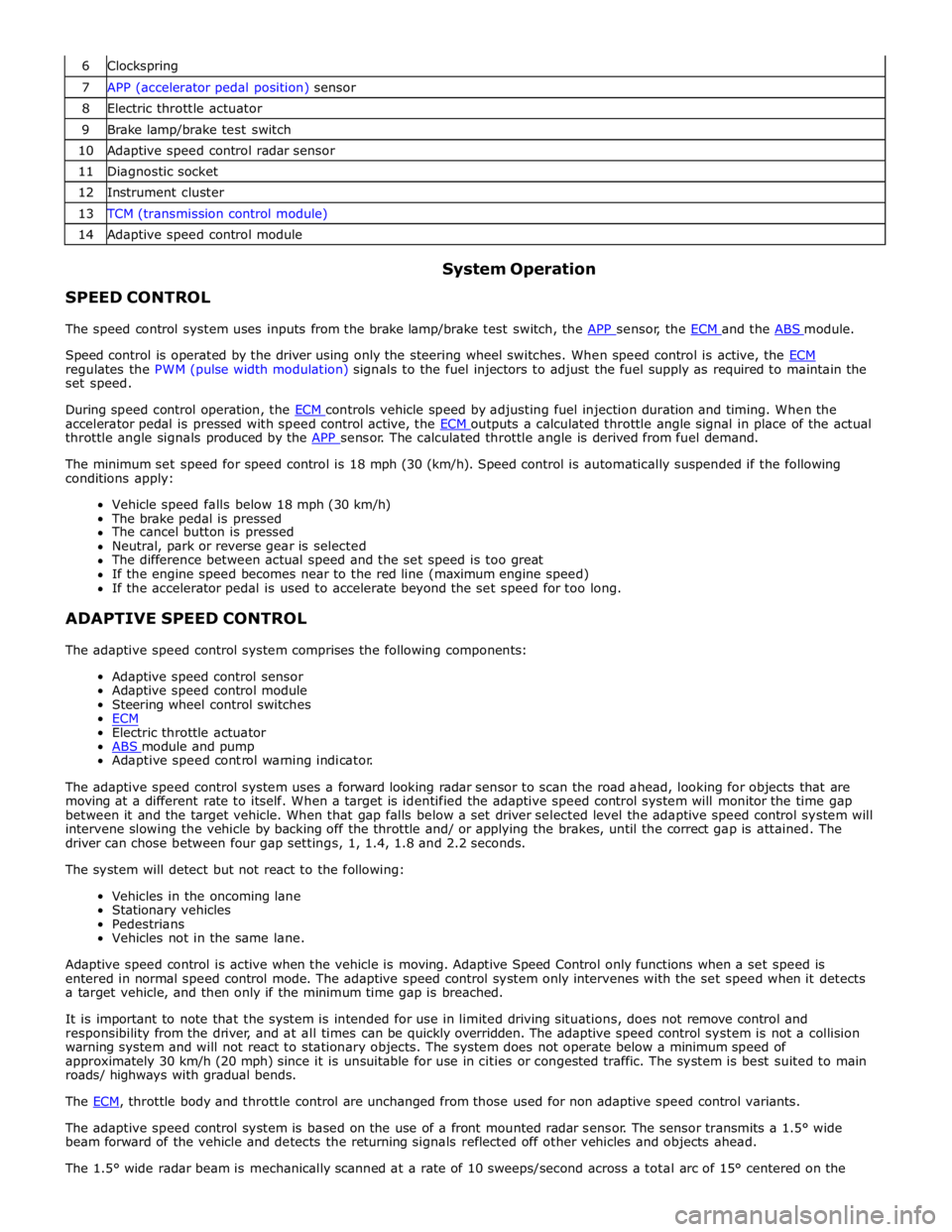
6 Clockspring 7 APP (accelerator pedal position) sensor 8 Electric throttle actuator 9 Brake lamp/brake test switch 10 Adaptive speed control radar sensor 11 Diagnostic socket 12 Instrument cluster 13 TCM (transmission control module) 14 Adaptive speed control module
SPEED CONTROL System Operation
The speed control system uses inputs from the brake lamp/brake test switch, the APP sensor, the ECM and the ABS module.
Speed control is operated by the driver using only the steering wheel switches. When speed control is active, the ECM regulates the PWM (pulse width modulation) signals to the fuel injectors to adjust the fuel supply as required to maintain the
set speed.
During speed control operation, the ECM controls vehicle speed by adjusting fuel injection duration and timing. When the accelerator pedal is pressed with speed control active, the ECM outputs a calculated throttle angle signal in place of the actual throttle angle signals produced by the APP sensor. The calculated throttle angle is derived from fuel demand.
The minimum set speed for speed control is 18 mph (30 (km/h). Speed control is automatically suspended if the following
conditions apply:
Vehicle speed falls below 18 mph (30 km/h)
The brake pedal is pressed
The cancel button is pressed
Neutral, park or reverse gear is selected
The difference between actual speed and the set speed is too great
If the engine speed becomes near to the red line (maximum engine speed)
If the accelerator pedal is used to accelerate beyond the set speed for too long.
ADAPTIVE SPEED CONTROL
The adaptive speed control system comprises the following components:
Adaptive speed control sensor
Adaptive speed control module
Steering wheel control switches
ECM
Electric throttle actuator
ABS module and pump Adaptive speed control warning indicator.
The adaptive speed control system uses a forward looking radar sensor to scan the road ahead, looking for objects that are
moving at a different rate to itself. When a target is identified the adaptive speed control system will monitor the time gap
between it and the target vehicle. When that gap falls below a set driver selected level the adaptive speed control system will
intervene slowing the vehicle by backing off the throttle and/ or applying the brakes, until the correct gap is attained. The
driver can chose between four gap settings, 1, 1.4, 1.8 and 2.2 seconds.
The system will detect but not react to the following:
Vehicles in the oncoming lane
Stationary vehicles
Pedestrians
Vehicles not in the same lane.
Adaptive speed control is active when the vehicle is moving. Adaptive Speed Control only functions when a set speed is
entered in normal speed control mode. The adaptive speed control system only intervenes with the set speed when it detects
a target vehicle, and then only if the minimum time gap is breached.
It is important to note that the system is intended for use in limited driving situations, does not remove control and
responsibility from the driver, and at all times can be quickly overridden. The adaptive speed control system is not a collision
warning system and will not react to stationary objects. The system does not operate below a minimum speed of
approximately 30 km/h (20 mph) since it is unsuitable for use in cities or congested traffic. The system is best suited to main
roads/ highways with gradual bends.
The ECM, throttle body and throttle control are unchanged from those used for non adaptive speed control variants.
The adaptive speed control system is based on the use of a front mounted radar sensor. The sensor transmits a 1.5° wide
beam forward of the vehicle and detects the returning signals reflected off other vehicles and objects ahead.
The 1.5° wide radar beam is mechanically scanned at a rate of 10 sweeps/second across a total arc of 15° centered on the
Page 1791 of 3039
Instrument Cluster - Instrument Cluster
Diagnosis and Testing
Principles of Operation Published: 22-Mar-2013
For a detailed description of the Instrument Cluster, refer to the relevant Description and Operation sections in the workshop
manual. REFER to: (413-01 Instrument Cluster)
Instrument Cluster (Description and Operation), Instrument Cluster (Description and Operation), Instrument Cluster (Description and Operation).
Inspection and Verification
CAUTION: Diagnosis by substitution from a donor vehicle is NOT acceptable. Substitution of control modules does not
guarantee confirmation of a fault, and may also cause additional faults in the vehicle being tested and/or the donor vehicle.
1. Verify the customer concern.
2. Visually inspect for obvious signs of damage and system integrity.
Visual Inspection
Mechanical Electrical
Fluid level(s)
Accessory installations
Fuse(s)
Wiring harness
Electrical connector(s)
Instrument cluster
Central Junction Box (CJB)
Engine Junction Box (EJB)
Driver Door Module (DDM)
Engine Control Module (ECM)
3. If an obvious cause for an observed or reported concern is found, correct the cause (if possible) before proceeding to
the next step.
4. If the cause is not visually evident, verify the symptom and refer to the Symptom Chart.
Symptom Chart
The instrument cluster contains a self-diagnostic mode known as engineering test mode (ETM). This can be used to show the
status of the instrument cluster inputs as well as a number of other useful features.
When in the ETM, the Message Centre displays internal data that can be cycled through. All functions except the message
centre display will continue to operate normally unless otherwise noted.
This document is to be used in conjunction with the instrument cluster ETM (see relevant section within this document) and
the Integrated Diagnostic System (IDS) facility; this does not supersede or replace the IDS facility.
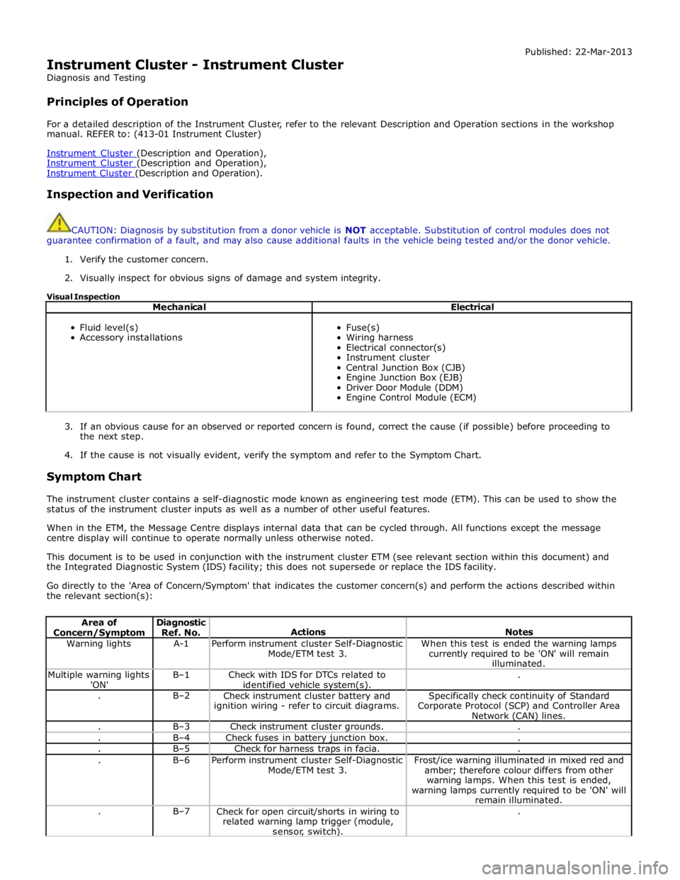
Go directly to the 'Area of Concern/Symptom' that indicates the customer concern(s) and perform the actions described within
the relevant section(s):
Area of Concern/Symptom Diagnostic
Ref. No.
Actions
Notes Warning lights A-1
Perform instrument cluster Self-Diagnostic
Mode/ETM test 3. When this test is ended the warning lamps
currently required to be 'ON' will remain
illuminated. Multiple warning lights
'ON' B–1
Check with IDS for DTCs related to
identified vehicle system(s). . . B–2
Check instrument cluster battery and
ignition wiring - refer to circuit diagrams. Specifically check continuity of Standard
Corporate Protocol (SCP) and Controller Area
Network (CAN) lines. . B–3 Check instrument cluster grounds. . . B–4 Check fuses in battery junction box. . . B–5 Check for harness traps in facia. . . B–6
Perform instrument cluster Self-Diagnostic
Mode/ETM test 3. Frost/ice warning illuminated in mixed red and
amber; therefore colour differs from other
warning lamps. When this test is ended,
warning lamps currently required to be 'ON' will
remain illuminated. . B–7
Check for open circuit/shorts in wiring to
related warning lamp trigger (module,
sensor, switch). .
Page 1878 of 3039
Battery, Mounting and Cables - Battery and Cables - Overview
Description and Operation
OVERVIEW
Single Battery Vehicles Published: 18-Jun-2014
Mounted on the battery negative terminal is a BMS (battery monitoring system) module. The BMS module is integral with the
battery negative cable and is controlled by the ECM (engine control module).
CAUTION: To avoid damaging the battery monitoring system module, always use a suitable body ground point rather than
the battery negative terminal when connecting a slave power supply to the vehicle.
If a new battery is fitted to the vehicle, the BMS module will require re-calibrating using the Jaguar approved diagnostic
system.
Fitted on the battery positive terminal is a transit relay. The transit relay must be removed from the vehicle during the
Pre-Delivery Inspection (PDI). For additional information, refer to the PDI Manual.
The vehicle battery provides power to the BJB (battery junction box). The BJB contains 3 megafuses, delivering power to the RJB (rear junction box), the CJB (central junction box) and the EJB (engine junction box). In addition to containing fuses and
relays, the RJB and RJB contain software to control a number of vehicle systems. These functions are covered in the appropriate sections of this manual.
Dual Battery System Vehicles - TD42.2L Engine Variants Only
Two batteries are fitted to accommodate the dual battery system used for the Stop/Start system.
A primary battery is located in the luggage compartment floor in a plastic molded tray and secured with a metal rod. The
secondary battery is located in the DBJB (dual battery junction box).
The primary battery is a 90Ahr, 850A CCA AGM Battery.
The secondary battery is a 14Ahr, 200A CCA Absorbed Glass Mat (AGM) Battery.
A BMS (battery monitoring system) control module is mounted on the primary battery negative terminal. The BMS control
module is integral with the battery negative cable and is controlled by the GWM (gateway module).
CAUTION: To avoid damaging the BMS control module, always use the ground (negative (-)) terminal stud point on the
right side top mount. Never connect directly to the primary battery negative terminal when connecting a slave power supply to
the vehicle, the BMS control module can be damaged.
If a new primary battery is fitted to the vehicle, the BMS control module will require re-calibrating using a Jaguar approved
diagnostic system.
When the vehicle leaves the factory, a transit relay is fitted to the battery positive terminal. The transit relay is connected to
the CJB which limits the electrical functions to essential items only, to reduce loads on the primary battery. The transit relay must be removed from the vehicle during the PDI (Pre-Delivery Inspection). For additional information, refer to the PDI.
The primary battery provides power to the BJB. The BJB contains three megafuses, delivering power to the RJB, the EJB and the starter motor and generator. In addition to containing fuses and relays, the RJB and CJB contain software to control a number of vehicle systems. These functions are covered in the appropriate sections of this manual.
A jump start terminal is located adjacent to the EJB. A cover protects the terminal when not in use. If jump starting is
required, the cover must be removed and the positive (+) jump lead attached securely. The negative (-) jump lead is attached
to a stud located on the right side top mount in the engine compartment. The cover must be fitted to the positive terminal
when not in use.
Dual Battery System
The dual battery system is used on vehicles with the stop/start system. The dual battery system prevents the vehicle
electrical systems being subjected to undesirably low voltages during repeated engine restarts. If the electrical systems are
subject to low voltages the customer may notice degraded performance of components and systems and incorrect fault DTC
(diagnostic trouble code)'s may be stored.
The dual battery system isolates all electrical components and systems sensitive to low supply voltage from the primary
battery while an engine start is in progress, and supplies them from the secondary battery. Without the dual battery system,
the electrical power required by the TSS (Tandem Solenoid Starter) motor to crank the engine for each start would cause a
voltage drop across the entire vehicle electrical network, and cause control modules to function incorrectly and in some cases
reset and/or record DTC's.
If the dual battery system is unable to prevent electrical supplies to the vehicle systems being subjected to low voltage levels
during engine stop/start operations, due to the condition of the primary and/or secondary batteries or a system fault, the
stop/start feature is disabled.