Timing JAGUAR XFR 2010 1.G Workshop Manual
[x] Cancel search | Manufacturer: JAGUAR, Model Year: 2010, Model line: XFR, Model: JAGUAR XFR 2010 1.GPages: 3039, PDF Size: 58.49 MB
Page 11 of 3039

Overview
System Operation and Component DescriptionDiagnosis and TestingEngineGeneral ProceduresEngine Oil Draining and Filling
Engine Oil Vacuum Draining and Filling
Fuel Pump Camshaft Timing Check
Fuel Pump Camshaft Timing Adjustment
Valve Clearance Check
Valve Clearance AdjustmentRemoval and InstallationCamshaft LH
Camshaft RH
Crankshaft Front Seal
Crankshaft Pulley
Crankshaft Rear Seal
Cylinder Head LH
Cylinder Head RH
Engine Mount LH
Engine Mount RH
Exhaust Manifold LH
Exhaust Manifold RH
Flexplate
Oil Cooler
Oil Filter Element
Oil Pan
Oil Pan Extension
Oil Pump
Timing Cover
Timing Drive Components
Valve Cover LH
Valve Cover RH
Cylinder Block Oil Gallery Plug
Fuel Pump Camshaft - Assembly Part Number: INA Timing Drive
Fuel Pump Camshaft - Assembly Part Number: Tsubaki Timing Drive
Lower Timing Cover
ValvesRemovalEngineInstallationEngine
Page 15 of 3039

Catalyst Monitor Sensor RH
Crankshaft Position (CKP) Sensor
Engine Control Module (ECM)
Engine Coolant Temperature (ECT) Sensor
Engine Oil Level Sensor
Front Knock Sensor (KS) LH
Front Knock Sensor (KS) RH
Fuel Rail Pressure (FRP) Sensor
Heated Oxygen Sensor (HO2S) LH
Heated Oxygen Sensor (HO2S) RH
Manifold Absolute Pressure (MAP) Sensor
Mass Air Flow (MAF) Sensor
Rear Knock Sensor (KS) LH
Rear Knock Sensor (KS) RH
Variable Valve Timing (VVT) Oil Control Solenoid LH
Variable Valve Timing (VVT) Oil Control Solenoid RH307: Automatic Transmission/Transaxle
307-01B: Automatic Transmission/Transaxle - TDV6 3.0L Diesel /V8 5.0L Petrol/V8 S/C 5.0L
PetrolSpecificationDescription and OperationComponent Location
Overview
System Operation and Component DescriptionDiagnosis and TestingDiagnosticsGeneral ProceduresTransmission Fluid Level Check
Transmission Fluid Drain and RefillRemoval and InstallationInput Shaft Seal
Extension Housing Seal
Transmission Control Module (TCM) and Main Control Valve Body
Transmission Fluid Pan, Gasket and Filter
Transmission Support Insulator - V8 5.0L Petrol/V8 S/C 5.0L Petrol
Transmission, Transmission Fluid Cooler and Transmission Fluid Cooler Tubes - V8 5.0L Petrol/V8
S/C 5.0L Petrol
Transmission and Transmission Fluid Cooler - V8 5.0L Petrol/V8 S/C 5.0L PetrolRemovalTransmission - V8 5.0L Petrol/V8 S/C 5.0L PetrolInstallationTransmission - V8 5.0L Petrol/V8 S/C 5.0L Petrol
Page 55 of 3039
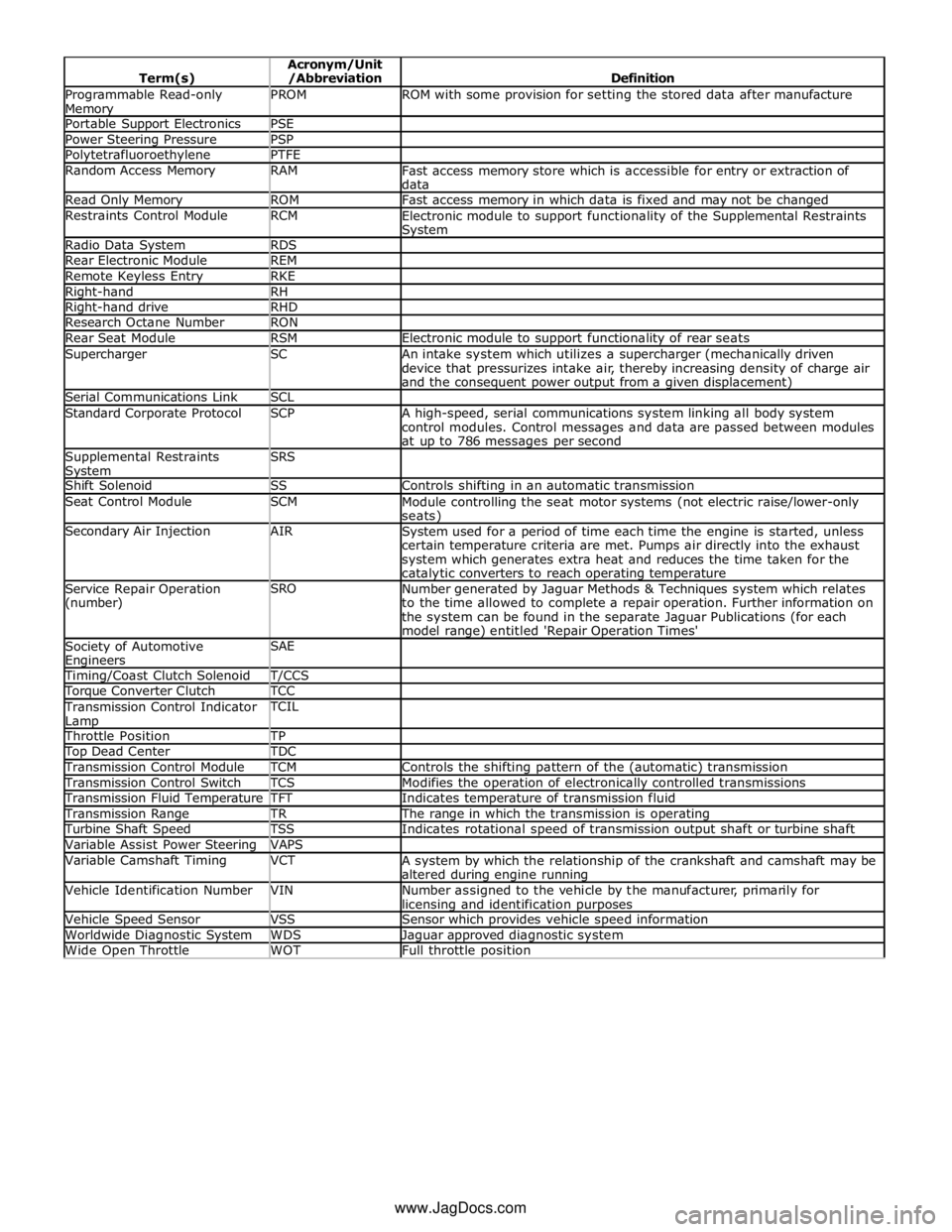
Programmable Read-only Memory PROM ROM with some provision for setting the stored data after manufacture Portable Support Electronics PSE Power Steering Pressure PSP Polytetrafluoroethylene PTFE Random Access Memory RAM
Fast access memory store which is accessible for entry or extraction of
data Read Only Memory ROM Fast access memory in which data is fixed and may not be changed Restraints Control Module RCM
Electronic module to support functionality of the Supplemental Restraints System Radio Data System RDS Rear Electronic Module REM Remote Keyless Entry RKE Right-hand RH Right-hand drive RHD Research Octane Number RON Rear Seat Module RSM Electronic module to support functionality of rear seats Supercharger SC
An intake system which utilizes a supercharger (mechanically driven
device that pressurizes intake air, thereby increasing density of charge air
and the consequent power output from a given displacement) Serial Communications Link SCL Standard Corporate Protocol SCP
A high-speed, serial communications system linking all body system
control modules. Control messages and data are passed between modules
at up to 786 messages per second Supplemental Restraints System SRS
Shift Solenoid SS Controls shifting in an automatic transmission Seat Control Module SCM
Module controlling the seat motor systems (not electric raise/lower-only seats) Secondary Air Injection AIR
System used for a period of time each time the engine is started, unless
certain temperature criteria are met. Pumps air directly into the exhaust
system which generates extra heat and reduces the time taken for the catalytic converters to reach operating temperature Service Repair Operation
(number) SRO
Number generated by Jaguar Methods & Techniques system which relates
to the time allowed to complete a repair operation. Further information on
the system can be found in the separate Jaguar Publications (for each
model range) entitled 'Repair Operation Times' Society of Automotive Engineers SAE
Timing/Coast Clutch Solenoid T/CCS Torque Converter Clutch TCC Transmission Control Indicator
Lamp TCIL
Throttle Position TP Top Dead Center TDC Transmission Control Module TCM Controls the shifting pattern of the (automatic) transmission Transmission Control Switch TCS Modifies the operation of electronically controlled transmissions Transmission Fluid Temperature TFT Indicates temperature of transmission fluid Transmission Range TR The range in which the transmission is operating Turbine Shaft Speed TSS Indicates rotational speed of transmission output shaft or turbine shaft Variable Assist Power Steering VAPS Variable Camshaft Timing VCT
A system by which the relationship of the crankshaft and camshaft may be
altered during engine running Vehicle Identification Number VIN
Number assigned to the vehicle by the manufacturer, primarily for licensing and identification purposes Vehicle Speed Sensor VSS Sensor which provides vehicle speed information Worldwide Diagnostic System WDS Jaguar approved diagnostic system Wide Open Throttle WOT Full throttle position www.JagDocs.com
Page 166 of 3039
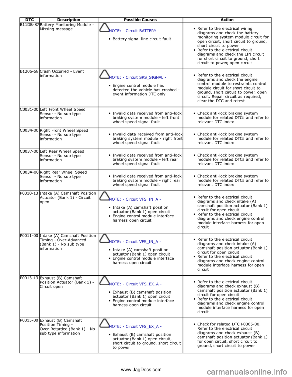
DTC Description Possible Causes Action B11DB-87
Battery Monitoring Module -
Missing message
NOTE: - Circuit BATTERY -
Battery signal line circuit fault
Refer to the electrical wiring
diagrams and check the battery
monitoring system module circuit for
open circuit, short circuit to ground,
short circuit to power
Refer to the electrical circuit
diagrams and check the LIN circuit
for short circuit to ground, short
circuit to power, open circuit B1206-68
Crash Occurred - Event
information
NOTE: - Circuit SRS_SIGNAL -
Engine control module has
detected the vehicle has crashed -
event information DTC only
Refer to the electrical circuit
diagrams and check the engine
control module to restraints control
module circuit for short circuit to
ground, short circuit to power, open
circuit. Repair circuit as required,
clear the DTC and retest C0031-00
Left Front Wheel Speed
Sensor - No sub type
information
Invalid data received from anti-lock
braking system module - left front
wheel speed signal fault
Check anti-lock braking system
module for related DTCs and refer to
relevant DTC index C0034-00
Right Front Wheel Speed
Sensor - No sub type
information
Invalid data received from anti-lock
braking system module - right front
wheel speed signal fault
Check anti-lock braking system
module for related DTCs and refer to
relevant DTC index C0037-00
Left Rear Wheel Speed
Sensor - No sub type
information
Invalid data received from anti-lock
braking system module - left rear
wheel speed signal fault
Check anti-lock braking system
module for related DTCs and refer to
relevant DTC index C003A-00
Right Rear Wheel Speed
Sensor - No sub type
information
Invalid data received from anti-lock
braking system module - right rear
wheel speed signal fault
Check anti-lock braking system
module for related DTCs and refer to
relevant DTC index P0010-13
Intake (A) Camshaft Position
Actuator (Bank 1) - Circuit
open
NOTE: - Circuit VFS_IN_A -
Intake (A) camshaft position
actuator (Bank 1) open circuit
Engine control module interface
harness open circuit
Refer to the electrical circuit
diagrams and check intake (A)
camshaft position actuator (Bank 1)
circuit for open circuit
Refer to the electrical circuit
diagrams and check engine control
module interface harness for open
circuit P0011-00
Intake (A) Camshaft Position
Timing - Over-Advanced
(Bank 1) - No sub type
information
NOTE: - Circuit VFS_IN_A -
Intake (A) camshaft position
actuator (Bank 1) open circuit
Engine control module interface
harness open circuit
Refer to the electrical circuit
diagrams and check intake (A)
camshaft position actuator (Bank 1)
circuit for open circuit
Refer to the electrical circuit
diagrams and check engine control
module interface harness for open
circuit P0013-13
Exhaust (B) Camshaft
Position Actuator (Bank 1) -
Circuit open
NOTE: - Circuit VFS_EX_A -
Exhaust (B) camshaft position
actuator (Bank 1) open circuit
Engine control module interface
harness open circuit
Refer to the electrical circuit
diagrams and check exhaust (B)
camshaft position actuator (Bank 1)
circuit for open circuit
Refer to the electrical circuit
diagrams and check engine control
module interface harness for open
circuit P0015-00
Exhaust (B) Camshaft
Position Timing -
Over-Retarded (Bank 1) - No
sub type information
NOTE: - Circuit VFS_EX_A -
Exhaust (B) camshaft position
actuator (Bank 1) open circuit,
short circuit to ground, short circuit
to power
Check for related DTC P0365-00.
Refer to the electrical circuit
diagrams and check exhaust (B)
camshaft position actuator (Bank 1)
for open circuit, short circuit to
ground, short circuit to power www.JagDocs.com
Page 167 of 3039
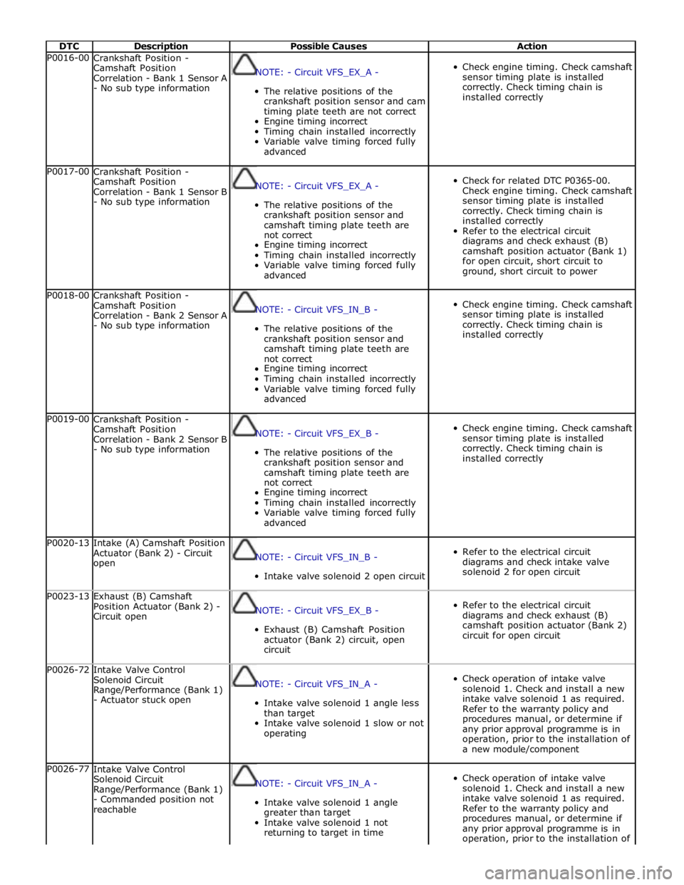
DTC Description Possible Causes Action P0016-00
Crankshaft Position -
Camshaft Position
Correlation - Bank 1 Sensor A
- No sub type information
NOTE: - Circuit VFS_EX_A -
The relative positions of the
crankshaft position sensor and cam
timing plate teeth are not correct
Engine timing incorrect
Timing chain installed incorrectly
Variable valve timing forced fully
advanced
Check engine timing. Check camshaft
sensor timing plate is installed
correctly. Check timing chain is
installed correctly P0017-00
Crankshaft Position -
Camshaft Position
Correlation - Bank 1 Sensor B
- No sub type information
NOTE: - Circuit VFS_EX_A -
The relative positions of the
crankshaft position sensor and
camshaft timing plate teeth are
not correct
Engine timing incorrect
Timing chain installed incorrectly
Variable valve timing forced fully
advanced
Check for related DTC P0365-00.
Check engine timing. Check camshaft
sensor timing plate is installed
correctly. Check timing chain is
installed correctly
Refer to the electrical circuit
diagrams and check exhaust (B)
camshaft position actuator (Bank 1)
for open circuit, short circuit to
ground, short circuit to power P0018-00
Crankshaft Position -
Camshaft Position
Correlation - Bank 2 Sensor A
- No sub type information
NOTE: - Circuit VFS_IN_B -
The relative positions of the
crankshaft position sensor and
camshaft timing plate teeth are
not correct
Engine timing incorrect
Timing chain installed incorrectly
Variable valve timing forced fully
advanced
Check engine timing. Check camshaft
sensor timing plate is installed
correctly. Check timing chain is
installed correctly P0019-00
Crankshaft Position -
Camshaft Position
Correlation - Bank 2 Sensor B
- No sub type information
NOTE: - Circuit VFS_EX_B -
The relative positions of the
crankshaft position sensor and
camshaft timing plate teeth are
not correct
Engine timing incorrect
Timing chain installed incorrectly
Variable valve timing forced fully
advanced
Check engine timing. Check camshaft
sensor timing plate is installed
correctly. Check timing chain is
installed correctly P0020-13
Intake (A) Camshaft Position
Actuator (Bank 2) - Circuit
open
NOTE: - Circuit VFS_IN_B -
Intake valve solenoid 2 open circuit
Refer to the electrical circuit
diagrams and check intake valve
solenoid 2 for open circuit P0023-13
Exhaust (B) Camshaft
Position Actuator (Bank 2) -
Circuit open
NOTE: - Circuit VFS_EX_B -
Exhaust (B) Camshaft Position
actuator (Bank 2) circuit, open
circuit
Refer to the electrical circuit
diagrams and check exhaust (B)
camshaft position actuator (Bank 2)
circuit for open circuit P0026-72
Intake Valve Control
Solenoid Circuit
Range/Performance (Bank 1)
- Actuator stuck open
NOTE: - Circuit VFS_IN_A -
Intake valve solenoid 1 angle less
than target
Intake valve solenoid 1 slow or not
operating
Check operation of intake valve
solenoid 1. Check and install a new
intake valve solenoid 1 as required.
Refer to the warranty policy and
procedures manual, or determine if
any prior approval programme is in
operation, prior to the installation of
a new module/component P0026-77
Intake Valve Control
Solenoid Circuit
Range/Performance (Bank 1)
- Commanded position not
reachable
NOTE: - Circuit VFS_IN_A -
Intake valve solenoid 1 angle
greater than target
Intake valve solenoid 1 not
returning to target in time
Check operation of intake valve
solenoid 1. Check and install a new
intake valve solenoid 1 as required.
Refer to the warranty policy and
procedures manual, or determine if
any prior approval programme is in
operation, prior to the installation of
Page 816 of 3039
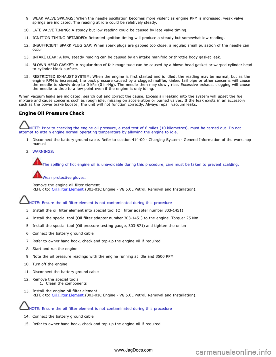
9. WEAK VALVE SPRINGS: When the needle oscillation becomes more violent as engine RPM is increased, weak valve
springs are indicated. The reading at idle could be relatively steady.
10. LATE VALVE TIMING: A steady but low reading could be caused by late valve timing.
11.
IGNITION TIMING RETARDED: Retarded ignition timing will produce a steady but somewhat low reading.
12.
INSUFFICIENT SPARK PLUG GAP: When spark plugs are gapped too close, a regular, small pulsation of the needle can
occur.
13. INTAKE LEAK: A low, steady reading can be caused by an intake manifold or throttle body gasket leak.
14.
BLOWN HEAD GASKET: A regular drop of fair magnitude can be caused by a blown head gasket or warped cylinder head
to cylinder block surface.
15.
RESTRICTED EXHAUST SYSTEM: When the engine is first started and is idled, the reading may be normal, but as the
engine RPM is increased, the back pressure caused by a clogged muffler, kinked tail pipe or other concerns will cause
the needle to slowly drop to 0 kPa (0 in-Hg). The needle then may slowly rise. Excessive exhaust clogging will cause
the needle to drop to a low point even if the engine is only idling.
When vacuum leaks are indicated, search out and correct the cause. Excess air leaking into the system will upset the fuel
mixture and cause concerns such as rough idle, missing on acceleration or burned valves. If the leak exists in an accessory
such as the power brake booster, the unit will not function correctly. Always repair vacuum leaks.
Engine Oil Pressure Check
NOTE: Prior to checking the engine oil pressure, a road test of 6 miles (10 kilometres), must be carried out. Do not
attempt to attain engine normal operating temperature by allowing the engine to idle.
1. Disconnect the battery ground cable. Refer to section 414-00 - Charging System - General Information of the workshop
manual
2. WARNINGS:
The spilling of hot engine oil is unavoidable during this procedure, care must be taken to prevent scalding.
Wear protective gloves.
Remove the engine oil filter element
REFER to: Oil Filter Element (303-01C Engine - V8 5.0L Petrol, Removal and Installation).
NOTE: Ensure the oil filter element is not contaminated during this procedure
3. Install the oil filter element into special tool (Oil filter adapter number 303-1451)
4. Install the special tool (Oil filter adapter number 303-1451) to the engine. Torque: 25 Nm
5. Install the special tool (Oil pressure testing gauge, 303-871) and tighten the union
6. Connect the battery ground cable
7. Refer to owner hand book, check and top-up the engine oil if required
8. Start and run the engine
9. Note the oil pressure readings with the engine running at idle and 3500 RPM
10.
Turn off the engine
11.
Disconnect the battery ground cable
12. Remove the special tools
1. Clean the components
13.
Install the engine oil filter element
REFER to: Oil Filter Element (303-01C Engine - V8 5.0L Petrol, Removal and Installation).
NOTE: Ensure the oil filter element is not contaminated during this procedure
14.
Connect the battery ground cable
15. Refer to owner hand book, check and top-up the engine oil if required
www.JagDocs.com
Page 845 of 3039

Item Specification Camshaft journal maximum run out limit (mm) Camshaft journals to end journals 0.03 Camshaft journals to adjacent journals 0.015 Camshaft journal maximum out of round (mm) - all journals 0.005 Torque Specification
NOTE: A = Refer to procedure for correct torque sequence.
Description Nm lb-ft lb-in Engine cover mounting bolts 10 7 - Accessory drive belt tensioner retaining bolt 40 30 - Supercharger belt idler/tensioner bracket retaining bolts 25 18 - Secondary drive belt idler retaining bolts 40 30 - Power steering pump pulley retaining bolts 25 18 - Power steering pump retaining bolts 25 18 - Power steering pump bracket to engine retaining bolts 25 18 - Generator retaining bolts 48 35 - Starter motor retaining bolts 48 35 - Air conditioning compressor retaining bolts 25 18 - Engine mounting to engine mounting bracket retaining nuts 48 35 - Engine mounting to subframe retaining nuts 63 46 - Engine mounting bracket to engine retaining bolts 48 35 - Crankshaft damper pulley retaining LH threaded bolt 200 + 270° 148 + 180° - Flexplate retaining bolts 45 + 90° 33 + 90° - Exhaust manifold heat shield retaining bolts A - - Exhaust manifold retaining bolts A - - Engine wiring harness bracket retaining bolts 10 7 - Coolant outlet pipe 10 7 - Intercooler retaining bolts 25 18 - Intake manifold retaining bolts 25 18 - Oil Cooler retaining bolts 13 10 - Knock sensor (KS) retaining bolt 20 14 - Ignition coil retaining bolts 8 - 71 Spark plugs 20 15 - Fuel rail retaining bolts A - - High pressure fuel pipe retaining bolts A - - High pressure fuel pump retaining bolts 12 9 - Oil filter housing assembly retaining bolts 12 9 - Oil filter cap 28 21 - Lifting eye bolts 25 + 90° 18 + 90° - Manifold absolute pressure and temperature (MAPT) sensor sensor retaining bolts 5 - 44 Coolant pump retaining bolts 12 9 - Variable valve timing (VVT) oil control solenoid retaining bolts 10 7 - Camshaft position (CMP) sensor retaining bolts 10 7 - Camshaft cover retaining bolts 13 10 - Front upper timing cover retaining bolts 12 9 - Front lower timing cover retaining bolts A - - Engine rear cover retaining bolts A - - VVT to camshaft retaining bolts 32 24 - Camshaft bearing caps retaining bolts 11 8 - Primary timing chain fixed guide retaining bolts 12 9 - Primary timing chain tensioner retaining bolts 12 9 - Primary timing chain tensioner guide blade retaining bolts 25 18 - Auxiliary chain tensioner guide retaining bolts 21 15 - Auxiliary chain fixed guide retaining bolt 12 9 - Oil pump sprocket retaining bolt 21 15 - Cylinder head retaining bolts A - - Engine oil level (EOL) sensor retaining bolt 12 9 - Oil pan to oil sump body retaining bolts 12 9 - Oil sump body to engine retaining bolts 25 18 - Oil pan drain plug 23 17 - Oil transfer tube to Oil pan body retaining bolts 11 8 - Oil pump to engine block retaining bolts 25 18 - Pick-up pipe to oil pump retaining bolts 12 9 - Windage tray retaining bolts 25 18 - Piston cooling jet retaining bolts 12 9 - Engine block coolant draining plug 50 37 - Connecting Rod bolts Stage 1 10 7 - Stage 2 50 37 -
Page 858 of 3039
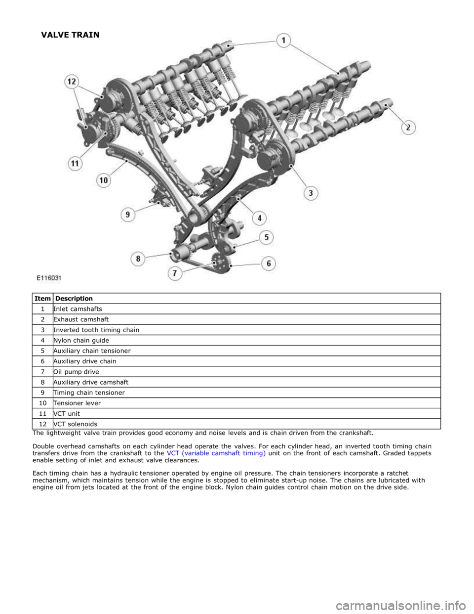
1 Inlet camshafts 2 Exhaust camshaft 3 Inverted tooth timing chain 4 Nylon chain guide 5 Auxiliary chain tensioner 6 Auxiliary drive chain 7 Oil pump drive 8 Auxiliary drive camshaft 9 Timing chain tensioner 10 Tensioner lever 11 VCT unit 12 VCT solenoids The lightweight valve train provides good economy and noise levels and is chain driven from the crankshaft.
Double overhead camshafts on each cylinder head operate the valves. For each cylinder head, an inverted tooth timing chain
transfers drive from the crankshaft to the VCT (variable camshaft timing) unit on the front of each camshaft. Graded tappets
enable setting of inlet and exhaust valve clearances.
Each timing chain has a hydraulic tensioner operated by engine oil pressure. The chain tensioners incorporate a ratchet
mechanism, which maintains tension while the engine is stopped to eliminate start-up noise. The chains are lubricated with
engine oil from jets located at the front of the engine block. Nylon chain guides control chain motion on the drive side. VALVE TRAIN
Page 859 of 3039
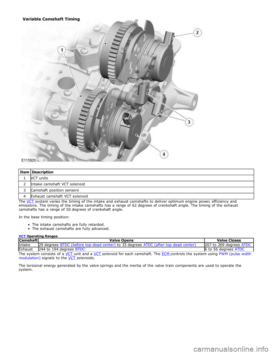
1 VCT units 2 Intake camshaft VCT solenoid 3 Camshaft position sensors 4 Exhaust camshaft VCT solenoid The VCT system varies the timing of the intake and exhaust camshafts to deliver optimum engine power, efficiency and emissions. The timing of the intake camshafts has a range of 62 degrees of crankshaft angle. The timing of the exhaust
camshafts has a range of 50 degrees of crankshaft angle.
In the base timing position:
The intake camshafts are fully retarded.
The exhaust camshafts are fully advanced.
VCT Operating Ranges
Camshaft Valve Opens Valve Closes Intake 29 degrees BTDC (before top dead center) to 33 degrees ATDC (after top dead center) 207 to 269 degrees ATDC Exhaust 244 to 194 degrees BTDC 6 to 56 degrees ATDC The system consists of a VCT unit and a VCT solenoid for each camshaft. The ECM controls the system using PWM (pulse width modulation) signals to the VCT solenoids.
The torsional energy generated by the valve springs and the inertia of the valve train components are used to operate the
system. Variable Camshaft Timing
Page 860 of 3039

1 Bolt (3 off) 2 VCT unit 3 Filter 4 Camshaft 5 Inner plate 6 Housing and sprocket 7 Rotor assembly 8 Reed plate 9 Spring and lock pin 10 Spring (3 off) 11 Tip seal (3 off) 12 Spring (2 off) 13 Tip seal (2 off) 14 Spring The VCT units change the position of the camshafts in relation to the timing chains.