lock JAGUAR XJ6 1994 2.G User Guide
[x] Cancel search | Manufacturer: JAGUAR, Model Year: 1994, Model line: XJ6, Model: JAGUAR XJ6 1994 2.GPages: 521, PDF Size: 17.35 MB
Page 35 of 521
gg Jacking, lifting & Vehicle Recovery
2.2.4 Transporting
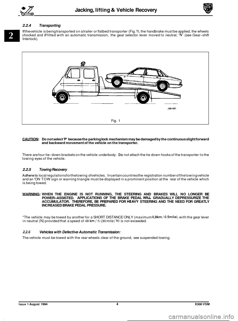
If thevehicle is being transported on a trailer or flatbed transporter (Fig. I), the handbrake must be applied, the wheels
chocked and if fitted with an automatic transmission, the gear selector lever moved to neutral, 'N' (see Gear-shift
Interlock).
e
JOS-031
Fig. 1
CAUTION: Do not select 'P' because the parking lock mechanism may be damaged by the continuous slight forward
and backward movement of the vehicle on the transporter.
There are four tie-down brackets on the vehicle underbody. Do not attach the tie down hooks of the transporter to the
towing eyes of the vehicle.
2.2.5 Towing Recovery
Adhereto local regulationsforthetowing ofvehicles. In certain countriesthe registration number ofthetowing vehicle
and an 'ON TOW sign or warning triangle must be displayed in a prominent position at the rear of the vehicle which
is being towed.
WARNING: WHEN THE ENGINE
IS NOT RUNNING, THE STEERING AND BRAKES WILL NO LONGER BE
ACCUMULATOR. THEREFORE, BE PREPARED FOR
HEAVY STEERING AND THE NEED FOR GREATLY
INCREASED BRAKE PEDAL PRESSURE.
POWER-ASSISTED.
APPLICATIONS
OF THE BRAKE PEDAL WILL GRADUALLY DEPRESSURIZE THE
*The vehicle may be towed by another for a SHORT DISTANCE ONLY (maximum
0,8km / O.Smile), with the gear lever
in neutral (N) provided that a speed of 48 km / h (30 mile / h) is not exceeded.
2.2.6
The vehicle must be towed with the rear wheels clear of the ground, see suspended towing.
Vehicles with Defective Automatic Transmission:
Issue 1 August 1994 4 X300 VSM
Page 36 of 521
Jacking, lifting & Vehicle Recovery gg
2.2.7 Suspended Towing
CAUTION: Do not tow with sling-type equipment as damage to the bodywork may result. Do not front suspend tow vehides with automatic transmission.
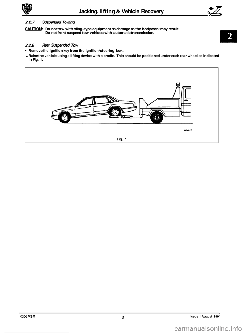
2.2.8 Rear Suspended Tow
Remove the ignition key from the ignition /steering lock.
. Raise the vehicle using a lifting device with a cradle. This should be positioned under each rear wheel as indicated
in Fig. 1.
0
0
0
J08-026
Fig. 1
Issue 1 August 1994 5 X300 VSM
Page 39 of 521
Engine (AJ16)
Description
Camshaft timing tool
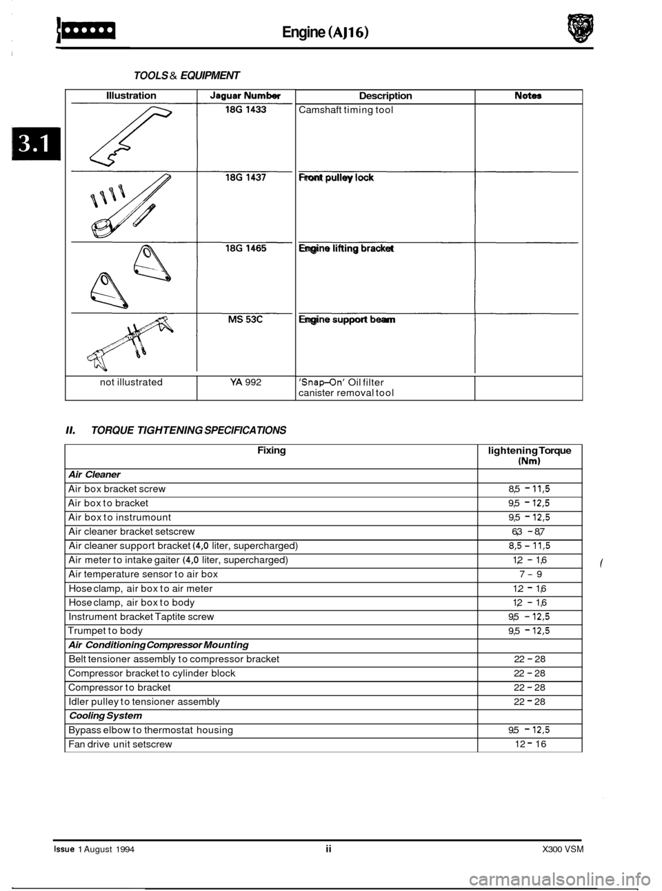
TOOLS & EQUIPMENT
Not- Illustration I JaguarNumber
L L
11. TORQUE TIGHTENING SPECIFICATIONS
not illustrated YA 992
Fixing
Air Cleaner
Air box bracket screw
Air box to bracket
Air box to instrumount
Air cleaner bracket setscrew
Air cleaner support bracket
(4,O liter, supercharged)
Air meter to intake gaiter
(4,O liter, supercharged)
Air temperature sensor to air box
Hose clamp, air box to air meter
Hose clamp, air box to body
Instrument bracket Taptite screw
Trumpet to body
Air Conditioning Compressor Mounting
Belt tensioner assembly to compressor bracket
Compressor bracket to cylinder block
Compressor to bracket
Idler pulley to tensioner assembly
Cooling System
Bypass elbow to thermostat housing
Fan drive unit setscrew
lightening Torque
(Nm)
8,5 - 11,5
9,5 - 12,5
9,5 - 12,5
6,3 - 8,7
8,5- 11,5
1,2 - 1,6
7
-9
1.2
- 1,6
1,2
- 1,6
9,5
- 12,5
9,5 - 12,5
22 - 28
22
- 28
22
- 28
22
- 28
9.5
- 12,5
12 - 16
Front pulley lock
fi
Engine lifting bracket
fi
Engine support beam
fl
'Snap-On' Oil filter
canister removal tool
Issue 1 August 1994 ii X300 VSM
Page 40 of 521
Engine (AJ16) 1-
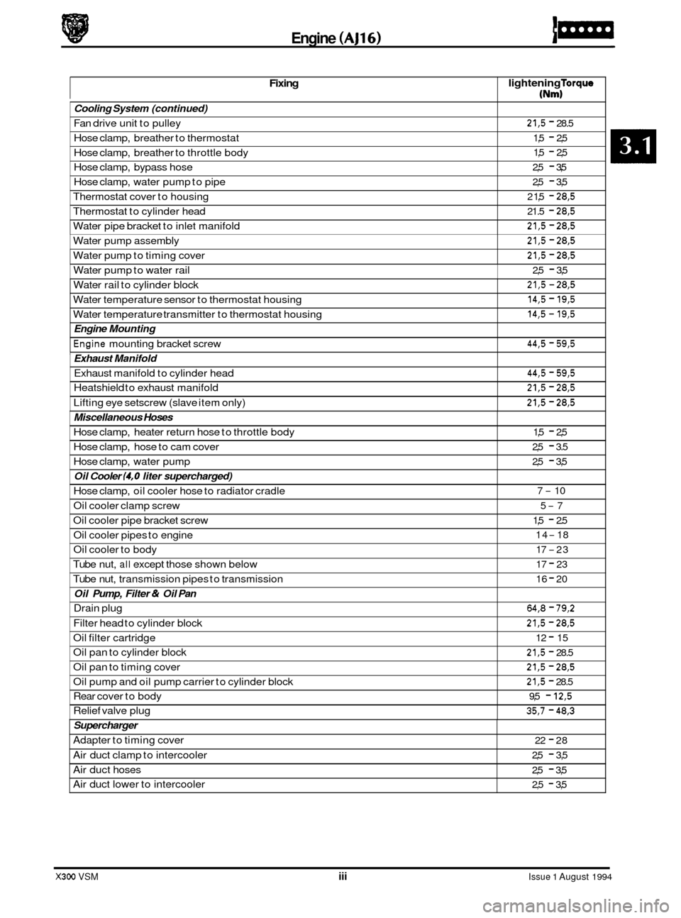
Fixing lightening Torque
(Nm)
Cooling System
(continued)
Fan drive unit to pulley
Hose clamp, breather to thermostat
Hose clamp, breather to throttle body
Hose clamp, bypass hose
Hose clamp, water pump to pipe
Thermostat cover to housing
Thermostat to cylinder head
Water pipe bracket to inlet manifold 21,5 - 28.5
1,5
- 2,5
1,5
- 2,5
2,5
- 3,5
2,5
- 3,5
2 1,5
- 28,5
21.5 - 28,5
21,5 - 28,5
Water pump assembly
Water pump to timing cover 21,5 - 28,5
21,5 - 28,5
Water pump to water rail 2,5 - 3,5
Water rail to cylinder block
X300 VSM iii Issue 1 August 1994
21,5 - 28,5
@
Water temperature sensor to thermostat housing
Water temperature transmitter to thermostat housing 14,5 - 19,5
14,5 - 19,5
44,5 - 59,5
Engine Mounting
*Engine mounting bracket screw
' Exhaust Manifold
Exhaust manifold to cylinder head
Heatshield to exhaust manifold
Lifting eye setscrew (slave item only) 44,5 - 59,5
21,5 - 28,5
21,5 - 28,5
Miscellaneous Hoses
Hose clamp, heater return hose to throttle body
Hose clamp, hose to cam cover
Hose clamp, water pump
Oil Cooler (4,O liter supercharged)
Hose clamp, oil cooler hose to radiator cradle
Oil cooler clamp screw
5-7
Oil cooler pipe bracket screw
Oil cooler pipes to engine
Oil cooler to body
Tube nut,
all except those shown below
Tube nut, transmission pipes to transmission
1,5 - 2,5
2,5
- 3.5
2,5
- 3,5
7
- 10
1,5
- 2.5
14
- 18
17
-23
17
- 23
16
- 20
Oil Pump, Filter & Oil Pan
Drain plug 64,8 - 79,2
Filter head to cylinder block 21,5 - 28,5
Oil filter cartridge 12 - 15
Oil pan to cylinder block 21,5 - 28.5
Oil pan to timing cover 21,5 - 28,5
Oil pump and oil pump carrier to cylinder block 21,5 - 28.5
Rear cover to body 9,5 - 12,5
Relief valve plug 35,7 - 48,3
Supercharger
Adapter to timing cover
Air duct clamp to intercooler
Air duct hoses
Air duct lower to intercooler 22 - 28
2,5
- 3,5
2,5
- 3,5
2,5
- 3,5
Page 41 of 521
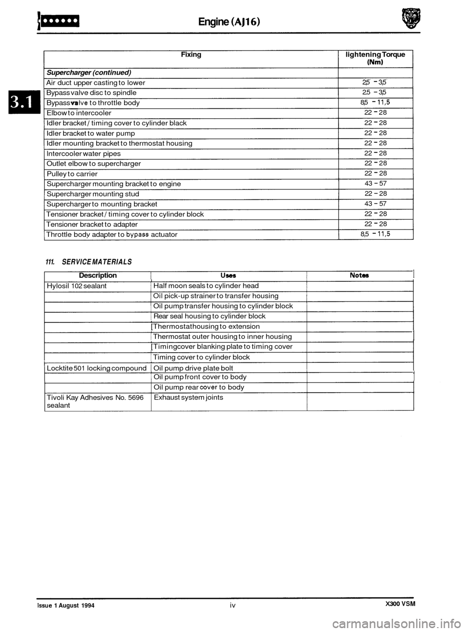
Idler bracket / timing cover to cylinder black
Idler bracket to water pump
Idler mounting bracket to thermostat housing
lntercooler water pipes
Outlet elbow to supercharger
Pulley to carrier 22 - 28
22
- 28
22
- 28
22
- 28
22
- 28
22
- 28
43
- 57
22
- 28
43
- 57
22
- 28
22
- 28
8,5
- 11,5
Supercharger mounting bracket to engine
Supercharger to mounting bracket
Supercharger
mounting stud
Tensioner bracket
/ timing cover to cylinder block
Tensioner bracket to adapter
Throttle bodv adapter to
bypass actuator
Engine (AJ16)
Fixing lightening Torque
Supercharger (continued)
Air duct upper casting to lower
Bypass valve disc to spindle
Bypass
mlve to throttle body
Elbow to intercooler
2,5 - 3,5
2.5
- 3,5
8,5
- 11,5
22 - 28 ~~ ~
111.
SERVICE MATERIALS
Description USOS Notea 1 I I Hylosil 102 sealant 1 Half moon seals to cylinder head I I Oil pick-up strainer to transfer housing I 1 Oil pump transfer housing to cylinder block 1
[ Rear seal housing to cylinder block , [Thermostat housing to extension , I Thermostat outer housing to inner housing 1 , [Timing cover blanking plate to timing cover 1 I I Timing cover to cylinder block
I Locktite 501 locking compound I Oil pump drive plate bolt
,
,
I Oil pump front cover to body 1
I Oil pump rear cover to body
I Exhaust system joints
Tivoli Kay Adhesives No. 5696
sealant
X300 VSM Issue 1 August 1994 iv
Page 43 of 521
Engine (AJ16)
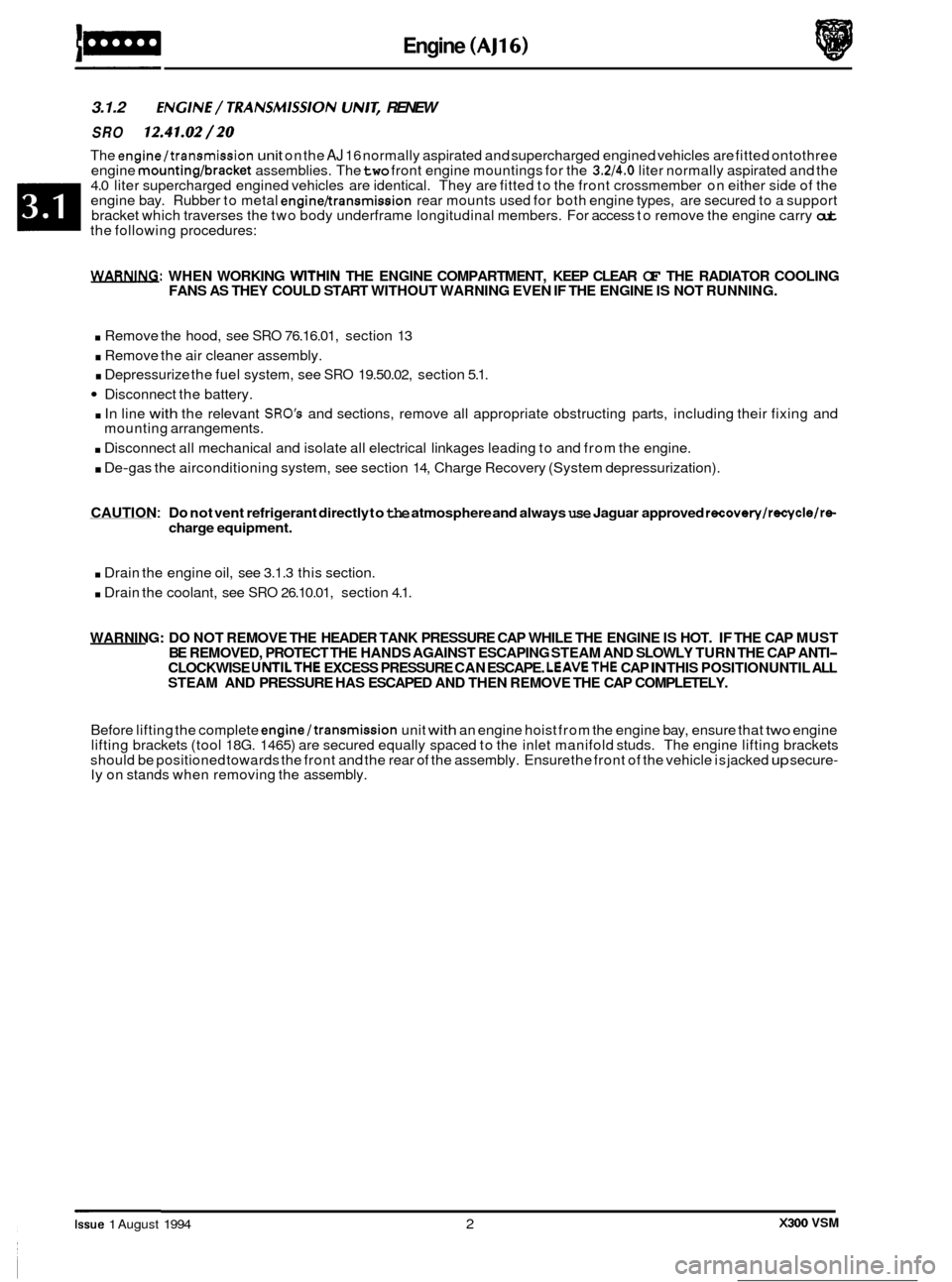
3.1.2 ENGlNE/ TRANSMlSSlON UN/& RENEW
SRO 12.41.02/20
The engine/transmission unit on the AJ 16 normally aspirated and supercharged engined vehicles are fitted ontothree
engine mounting/bracket assemblies. The two front engine mountings for the 3.2/4.0 liter normally aspirated and the
4.0 liter supercharged engined vehicles are identical. They are fitted to the front crossmember on either side of the
engine bay. Rubber to metal
engine/transmission rear mounts used for both engine types, are secured to a support
bracket which traverses the two body underframe longitudinal members. For access to remove the engine carry out the following procedures:
WARNING: WHEN WORKING WlTHlN THE ENGINE COMPARTMENT, KEEP CLEAR OF THE RADIATOR COOLING
FANS AS THEY COULD START WITHOUT WARNING EVEN IF THE ENGINE IS NOT RUNNING.
. Remove the hood, see SRO 76.16.01, section 13
. Remove the air cleaner assembly.
. Depressurize the fuel system, see SRO 19.50.02, section 5.1.
Disconnect the battery.
. In line with the relevant SRO's and sections, remove all appropriate obstructing parts, including their fixing and
. Disconnect all mechanical and isolate all electrical linkages leading to and from the engine.
. De-gas the airconditioning system, see section 14, Charge Recovery (System depressurization).
mounting
arrangements.
CAUTION : Do not vent refrigerant directly to the atmosphere and always use Jaguar approved recovery/recycle/re- charge equipment.
. Drain the engine oil, see 3.1.3 this section.
. Drain the coolant, see SRO 26.10.01, section 4.1.
WARNING: DO NOT REMOVE THE HEADER TANK PRESSURE CAP WHILE THE ENGINE IS HOT. IF THE CAP MUST
BE REMOVED, PROTECT THE HANDS AGAINST ESCAPING STEAM AND SLOWLY TURN THE CAP ANTI- CLOCKWISE UNTILTHE EXCESS PRESSURE CAN ESCAPE. LEAVETHE CAP IN THIS POSITION UNTIL ALL
STEAM AND PRESSURE HAS ESCAPED AND THEN REMOVE THE CAP COMPLETELY.
Before lifting the complete engine/transmission unit with an engine hoist from the engine bay, ensure that two engine
lifting brackets (tool 18G. 1465) are secured equally spaced to the inlet manifold studs. The engine lifting brackets
should be positioned towards the front and the rear of the assembly. Ensure the front of the vehicle is jacked
up secure- ly on stands when removing the assembly.
e
0
0
X300 VSM Issue 1 August 1994 2
Page 49 of 521
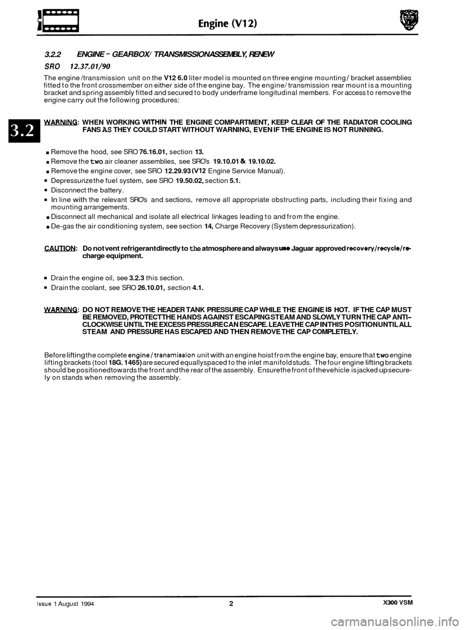
3.2.2 ENGINE - GEARBOX/ TRANSMISSION
ASSEMBLY, RENEW
SRO 12.37.01/90
The engine /transmission unit on the V12 6.0 liter model is mounted on three engine mounting / bracket assemblies
fitted to the front crossmember on either side of the engine bay. The engine/ transmission rear mount is a mounting
bracket and spring assembly fitted and secured to body underframe longitudinal members. For access to remove the
engine carry
out the following procedures:
WARNING: WHEN WORKING WITHIN THE ENGINE COMPARTMENT, KEEP CLEAR OF THE RADIATOR COOLING
FANS AS THEY COULD START WITHOUT WARNING, EVEN IF THE ENGINE IS NOT RUNNING.
. Remove the hood, see SRO 76.16.01, section 13.
. Remove the two air cleaner assemblies, see SRO’s 19.10.01 & 19.10.02.
. Remove the engine cover, see SRO 12.29.93 (V12 Engine Service Manual).
Depressurize the fuel system, see SRO 19.50.02, section 5.1.
In line with the relevant SRO’s and sections, remove all appropriate obstructing parts, including their fixing and
. Disconnect all mechanical and isolate all electrical linkages leading to and from the engine.
. De-gas the air conditioning system, see section 14, Charge Recovery (System depressurization).
Disconnect
the battery.
mounting arrangements.
CAUTION: Do
not vent refrigerant directly to the atmosphere and always use Jaguar approved recovery/recycle/ra charge equipment.
Drain the engine oil, see 3.2.3 this section.
Drain the coolant, see SRO 26.10.01, section 4.1.
WARNING: DO NOT REMOVE THE HEADER TANK PRESSURE CAP WHILE THE ENGINE IS HOT. IF THE CAP MUST
BE REMOVED, PROTECT THE HANDS AGAINST ESCAPING STEAM AND SLOWLY TURN THE CAP ANTI- CLOCKWISE UNTIL THE EXCESS PRESSURE CAN ESCAPE. LEAVE THE CAP IN THIS POSITION UNTIL ALL
STEAM AND PRESSURE HAS ESCAPED AND THEN REMOVE THE CAP COMPLETELY.
Before
lifting the complete engine/transmission unit with an engine hoist from the engine bay, ensure that two engine
lifting brackets (tool 18G. 1465) are secured equallyspaced to the inlet manifold studs. The four engine lifting brackets
should be positioned towards the front and the rear of the assembly. Ensure the front of thevehicle is jacked
up secure- ly on stands when removing the assembly.
X300 VSM Issue 1 August 1994 2
Page 56 of 521
Cooling System (AJl6) m
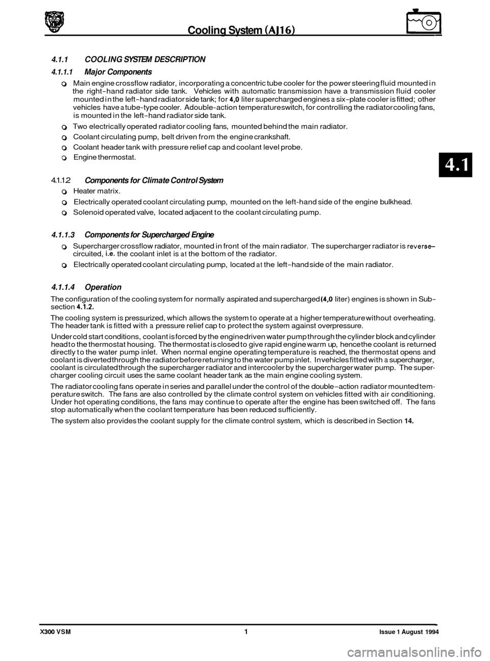
4.1.1 COOLING SYSTEM DESCRIPTION
4.1.1.1 Major Components
o Main engine crossflow radiator, incorporating a concentric tube cooler for the power steering fluid mounted in
the right
-hand radiator side tank. Vehicles with automatic transmission have a transmission fluid cooler
mounted in the left
-hand radiator side tank; for 4,O liter supercharged engines a six-plate cooler is fitted; other
vehicles have
a tube-type cooler. Adouble-action temperature switch, for controlling the radiator cooling fans,
is mounted in the left
-hand radiator side tank.
0 Two electrically operated radiator cooling fans, mounted behind the main radiator.
0 Coolant circulating pump, belt driven from the engine crankshaft.
0 Coolant header tank with pressure relief cap and coolant level probe.
o Engine thermostat.
4.1.1.2
0 Heater matrix.
o Electrically operated coolant circulating pump, mounted on the left-hand side of the engine bulkhead.
o Solenoid operated valve, located adjacent to the coolant circulating pump.
Components for Climate Control System
4.1.1.3 Components for Supercharged Engine
0 0 Supercharger crossflow radiator, mounted in front of the main radiator. The supercharger radiator is reverse- circuited, i.e. the coolant inlet is at the bottom of the radiator.
0 Electrically operated coolant circulating pump, located at the left-hand side of the main radiator.
4.1.1.4 Operation
The configuration of the cooling system for normally aspirated and supercharged (4,O liter) engines is shown in Sub- section 4.1.2.
The cooling system is pressurized, which allows the system to operate at a higher temperature without overheating.
The header tank is fitted with a pressure relief cap to protect the system against overpressure.
Under cold start conditions, coolant is forced by the engine driven water pump through the cylinder block and cylinder
head to the thermostat housing. The thermostat is closed to give rapid engine warm up, hence the coolant is returned
directly to the water pump inlet. When normal engine operating temperature is reached, the thermostat opens and
coolant is diverted through the radiator before returning to the water pump inlet. In vehicles fitted with
a supercharger,
coolant is circulated through the supercharger radiator and intercooler by the supercharger water pump. The super- charger cooling circuit uses the same coolant header tank as the main engine cooling system.
The radiator cooling fans operate in series and parallel under the control of the double
-action radiator mounted tem- perature switch. The fans are also controlled by the climate control system on vehicles fitted with air conditioning.
Under hot operating conditions, the fans may continue to operate after the engine has been switched off. The fans
stop automatically when the coolant temperature has been reduced sufficiently.
The system also provides the coolant supply for the climate control system, which is described in Section
14.
X300 VSM 1 Issue 1 August 1994
Page 58 of 521
area washed to remove all traces of coolant.
CAUTION: To prevent the possibility of damage to the heater circuit pump and supercharger pump (where fitted),
the pumps should be electrically isolated if the ignition has to be turned ON while the cooling system is
drained.
WARNING: DO NOT REMOVE THE HEADER TANK PRESSURE CAP WHILE THE ENGINE IS HOT. IF THE CAP MUST
BE REMOVED, PROTECT THE HANDS AGAINST ESCAPING STEAM AND SLOWLY TURN THE CAP ANTI
- CLOCKWISE UNTIL THE EXCESS PRESSURE CAN ESCAPE. LEAVE THE CAP IN THIS POSITION UNTIL
ALL THE STEAM AND PRESSURE HAS ESCAPED AND THEN REMOVE THE CAP COMPLETELY.
WARNING: WHEN DRAINING THE COOLANT WITH THE ENGINE HOT, PROTECT THE HANDS AGAINST CONTACT
WITH HOT COOLANT.
WARNING: WHEN WORKING WITHIN THE ENGINE COMPARTMENT, KEEP CLEAR OF THE RADIATOR COOLING
FANS. THE FANS COULD START WITHOUT WARNING EVEN IF THE ENGINE IS NOT RUNNING.
4.1.3.2 Working Practices
Whenfilling thesystem with coolant,ensurethatthevehicle isstanding on a level surfaceandthatthecoolant is poured
in slowly so that airlocks are not introduced into the system. Airlocks can seriously affect the operation of the climate
control system and can cause damage to the heater circuit pump (and supercharger circuit pump if fitted).
Cooling System (AJ16)
4.1.3 SERVICE PROCEDURES
4.1.3.1 Safety Precautions
The anti-freeze specified in Appendix AI must be used wherever possible. It is designed to afford the maximum cor- rosion protection to all metals found in the engine cooling system, as well as having the frost protection properties
necessary during the winter months.
Should
it not be available, then anti-freeze conforming to Ford Motor Company specification ESLbM97B49-A may be
used. To provide optimum temperature and corrosion protection, the specified anti-freeze concentration must always
be used.
Once coolant has been drained from the system,
it must be discarded and not reused. Anti-freeze is harmful to the
environment. Used coolant must be disposed of safely and never poured down a drain connected to the public sewer.
CAUTION: Never fill or topup the system with water only.
CAUTION : Anti-freeze is harmful to paintwork. Coolant spillages must be wiped up immediately and the affected
Hose clips should always be positioned so that there is proper access for tightening and that the clip does not foul or
interfere with the operation of any components.
Drive belts must always be tensioned to the specified value and the tension checked
at the correct point on the belt.
This information is given in Subsection IV in the preliminary pages.
0
When tightening components, the torque figures given in Sukection II in the preliminary pages should always be
used for the fastenings listed.
4.1.3.3 Coolant Change
The coolant must be changed at intervals of four years. The system should be drained from the radiator drain plug,
flushed and filled with fresh coolant. Flushing should be carried out thoroughly to remove all the old coolant from the
engineand heater matrix. (The heatervalve isopen withthe ignition OFF). AfterfiIling,checkthecoolant concentration
with a hydrometer. For the specified anti-freeze and coolant concentration, see Appendix AI.
X300 VSM 3 Issue 1 August 1994
Page 59 of 521
€3 Cooling System (AJ16)
4.1.4 DRAIN AND FILL PROCEDURES
4.1.4.1 Radiator, Drain
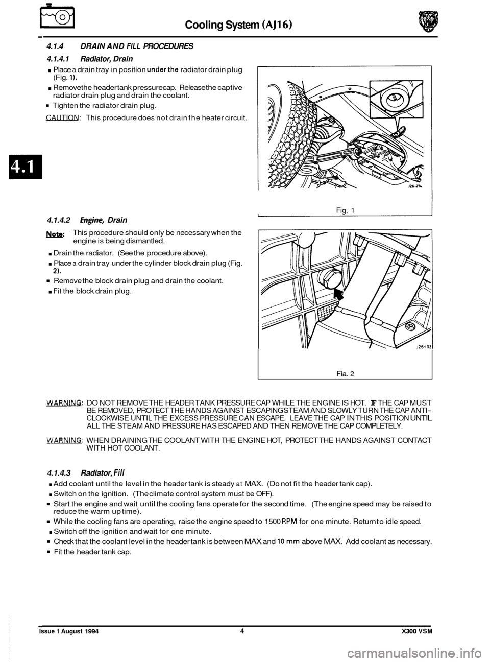
. Place a drain tray in position underthe radiator drain plug
. Remove the header tank pressure cap. Release the captive
Tighten the radiator drain plug.
CAUTION: This procedure does not drain the heater circuit.
(Fig. 1).
radiator drain plug and drain the coolant.
4.1.4.2 Engh-, Drain
m:
. Drain the radiator. (See the procedure above).
. Place a drain tray under the cylinder block drain plug (Fig.
Remove the block drain plug and drain the coolant.
. Fit the block drain plug.
This procedure
should only be necessary when the
engine is being dismantled.
2).
Fig. 1
Fia. 2
WAm. DO NOT REMOVE THE HEADER TANK PRESSURE CAP WHILE THE ENGINE IS HOT. IF THE CAP MUST
BE REMOVED, PROTECT THE HANDS AGAINST ESCAPING STEAM AND SLOWLY TURN THE CAP ANTI- CLOCKWISE UNTIL THE EXCESS PRESSURE CAN ESCAPE. LEAVE THE CAP IN THIS POSITION UNTIL ALL THE STEAM AND PRESSURE HAS ESCAPED AND THEN REMOVE THE CAP COMPLETELY.
WARNING: WHEN DRAINING THE COOLANT WITH THE ENGINE HOT, PROTECT THE HANDS AGAINST CONTACT
WITH HOT COOLANT.
4.1.4.3 Radiator, Fill
. Add coolant until the level in the header tank is steady at MAX. (Do not fit the header tank cap).
. Switch on the ignition. (The climate control system must be OFF).
Start the engine and wait until the cooling fans operate for the second time. (The engine speed may be raised to
While the cooling fans are operating, raise the engine speed to 1500 RPM for one minute. Return to idle speed.
. Switch off the ignition and wait for one minute.
Check that the coolant level in the header tank is between MAX and 10 mm above MAX. Add coolant as necessary.
Fit the header tank cap.
reduce
the warm up time).
Issue 1 August 1994 4 X300 VSM