JAGUAR XJ6 1994 2.G Workshop Manual
Manufacturer: JAGUAR, Model Year: 1994, Model line: XJ6, Model: JAGUAR XJ6 1994 2.GPages: 521, PDF Size: 17.35 MB
Page 341 of 521

iv
Page 342 of 521
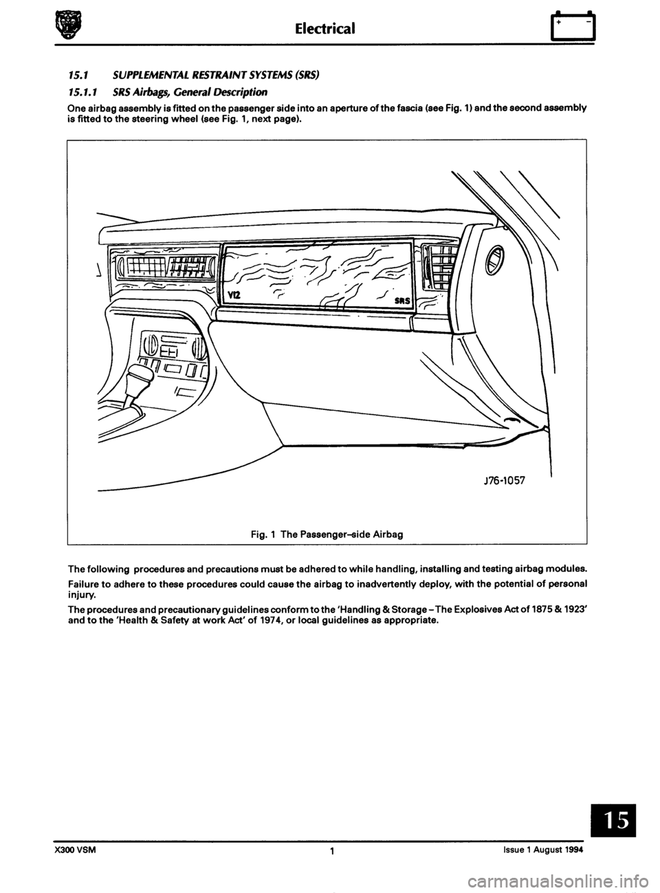
Page 343 of 521

15.1.2 Handling Undeployed Modules
The electrically-activated airbag module contains sodium azide and sodium nitrate which are poisonous and
extremely flammable substances.
Their contact with acid, water or heavy metals may produce harmful and irritating gases or combustible compounds.
The airbag module is
non-serviceable and must not be dismantled, punctured, incinerated or welded.
WARNING: DO NOT ATTEMPT ANY REPAIRS TO THE AIRBAG MODULE.
Never measure the resistance of the airbag module, as this may cause the airbag to deploy. Suspect modules must be returned to Jaguar Cars Ltd. or their importer for replacement.
Tampering or mishandling can result in personal injury.
Keep away from heat, sparks and open flames. Do not store
at temperatures exceeding 93O Celsius (200OF).
Keep away from electrical equipment as electrical contact may cause ignition.
Do not drop or impact airbag module.
Always position module 'cover
-up'.
Ensure that the connector is protected to prevent damage.
J76-1058
Fig. 1 The Driver-side Airbag
Store modules in a secure lockable cabinet.
Never position projectile material over the undeployed airbag as this can cause injury in the event of inadvertent
deployment.
Page 344 of 521
Do not wrap arms around module when carrying and always carry module with cover and ventsfacing awayfrom body
to avoid personal injury in the event of inadvertent deployment.
Never carry airbag module by wires or the connector.
The chemical propellant mixture deploying the airbag is
a solid and therefore inhalation exposure is unlikely even if module is ruptured without deployment.
As far as practicable, avoid skin contact with, or ingestion of, the materials present after combustion. Exposure to high
concentrations of propellant mixture may cause headache, nausea, blurred vision, faintness, cyanosis, lowering of
blood pressure, tachycardia and shortness of breath.
WARNING:SODlUM AZlDE HAS BEEN LISTED AS AN 'EXTRAORDINARY HAZARDOUS SUBSTANCE OR
CARCINOGEN BY THE STATE OF MASSACHUSETTS, USA. SODIUM AZlDE HAS BEEN LISTED ON THE 'RIGHT TO KNOW HAZARDOUS SUBSTANCE LIST' BY THE STATE OF NEW JERSEY AND IS ALSO
REGARDED AS A 'SPECIAL HEALTH HAZARD SUBSTANCE BY THE STATE. THE PROPELLANT MIXTURE IS SENSITIVE TO PREMATURE IGNITION BY ELECTRICAL SOURCES IF NOT PROPERLY PROTECTED AND
ISOLATED.
15.1.3 Emergency First Aid Procedures
If the airbag is ruptured without deployment and exposure to the propellant mixture occurs, observe the following
first-aid treatments:
0 Ingestion - Do not induce vomiting and seek prompt medical attention.
0 Skin contact- Immediately wash skin with soap and water and seek medical attention.
0 Eyes - Immediately flush eyes with water for at least 20 minutes and seek prompt medical attention.
0 Inhalation - Immediately move victim to fresh air and seek medical attention.
0 Physical trauma, eg burns, abrasions, or impact due to premature ignition or deployment of the inflator
assembly - Treat symptomatically and seek prompt medical attention.
0
15.1.4
See 'Emergency First Aid Procedures' above.
Prevent contact of the inflator with liquids, combustibles and flammable materials. Failure to followthese instructions
could result in chemical burns and personal injury.
Ensure modules are cool before handling.
After deployment the airbag surface contains small deposits of sodium hydroxide which can cause irritation to the skin
and eyes.
When handling deployed airbags, always wear rubber gloves to
BS 1651 grade 2 or equivalent, and chemical resistant
goggles to BS 2092 grade 2 or equivalent.
After handling deployed airbags, immediately wash hands and exposed skin surface areas with mild soap and water.
Sakty Procedures For Handling Depbyed (Fid) Modules
15.1.5 Safety Procedures For Handling Undeployed Damaged Modules
The material inside the module is hermetically sealed and is completely consumed during deployment.
No attempt should be made to open the module
as this leads to a risk of exposure to sodium azide.
In the unlikely event of
a gas generator being damaged, it must be examined by trained personnel before any attempt
is made to remove and/or deploy.
Full protective clothing must be worn when dealing with any spillage.
Ruptured units must be stored away from acids, halogens, heavy metals and metal salts. Damaged units may produce
hydrazoic acid if exposed to liquids.
Failure to comply with these instructions may result in fire, noxious fumes and severe personal injury or death.
X300 VSM 3 Issue 1 August 1994
Page 345 of 521
rl Electrical
15.1.6 Fire Hazard Infonnath
Thermal decomposition or combustion may produce dense smoke and other dangerous fumes which in fire situations
form
a highly toxic explosive.
In the event of fire the surrounding area must be evacuated and
all personnel kept well upwind of the area.
Full fire fighting protective gear and
a self contained breathing apparatus operating in the positive pressure mode must
be worn for combating fire. Material near fires must be cooled with water spray to prevent ignition.
Fires should be allowed to burn themselves
out if not threatening to life or property. If fire is threatening to life or prop- erty use copious quantities of water to extinguish.
15.1.7 Ventilath
Local exhaust ventilation designed by a professional engineer should be provided if vapours, fumes, or dusts are gen- erated whilst working with airbag module.
The latest issue of the manual for recommended practices on 'Industrial Ventilation' is available from the
ACGIH Com- mittee on Industrial Ventilation, PO Box 16153, Lansing, MI 48910, USA.
The need for local exhaust ventilation should be evaluated by a professional industrial hygienist.
15.1.8 Respiratory Precauth
To prevent the inhalation of dangerous fumes and dusts, an approved mask should be worn.
15.1.9 Eye Protection
Chemical protective goggles are recommended where there is a possibility of eye contact with the propellant.
Safety glasses with side shields are recommended for
all other operations.
15.1. I0 Protective Clothing
Approved protective gloves, overalls and shoes / boots should be worn.
15.1.1 1 Handling and Storage Precautions
Do not store airbag module near live electrical equipment or circuitry. Store in a dry environment at ambient tempera-
tures.
Good housekeeping and engineering practices should be employed to prevent the generation and accumulation of
dusts. Store in compliance with
all local state and federal regulations.
15.1.12 Driver And Passenger Airbag Modules Assembly / Removal / Service Instructions
Before starting work, ensure ignition switch is in 'IocK position, key is removed and negative terminal cable
is disconnected from the battery.
As the airbag is equipped with a back up power source and due to the risk of airbag being inadvertently
deployed, wait one minute or longer before starting work.
0 Disconnecting the battery cancels the memory for clock, radio, seats, mirrors, steering column and any other
components using battery power. Reset memory after work is completed.
0 Never use airbags from other vehicles, always use new parts.
0 After work is completed, reconnect battery and perform warning light check see diagnostic manual.
0 Never use electrical probes to check voltage or electrical resistance.
0 Disconnect the airbag before carrying out any work on, or in the vicinity of module, or when using electric weld- ing equipment.
0 Always ensure that battery negative has been disconnected for one minute or longer before commencing any
removal procedure.
EB
Issue 1 August 1994 4 X300 VSM
Page 346 of 521
15.1.13 Spillage and Leakage
If material is spilled or released,contact Jaguar Service for clean up procedures. All other personnel must be kept away
from contaminated area.
Do not dispose contaminated propellant or water into storm or sanitary sewers, ground water or soil.
Spills may be reportable to local state,
and/or federal authorities.
Material should
be disposed of by incineration or chemical oxidation under carefully controlled conditions by specially
trained individuals in accordance with local State and Federal regulations.
0
15.1.14 Scrapping Vehicles With Live Airbag(s)
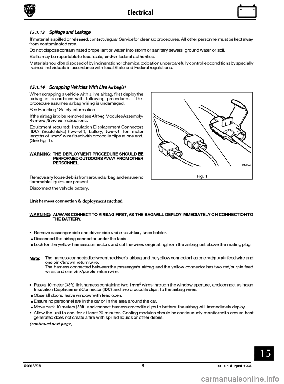
When scrapping a vehicle with a live airbag, first deploy the
airbag in accordance with following procedures. This
procedure assumes airbag wiring is undamaged.
See Handling
/ Safety information.
If the airbag is
to be removed see Airbag Modules Assembly/ Removal/Service Instructions.
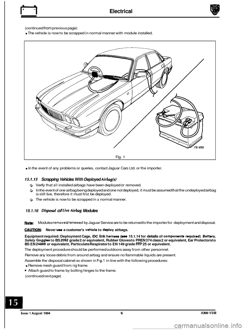
Equipment required: Insulation Displacement Connectors
(IDC) (Scotchloks) (two-off), battery, two-off ten meter
lengths of lmm2 wire fitted with crocodile clips at one end. (See Fig. 1).
WARNING: THE DEPLOYMENT PROCEDURE SHOULD BE PERFORMED OUTDOORS AWAY FROM OTHER
PERSONNEL.
Remove any loose debrisfrom around airbag and ensure no
flammable liquids are present.
Disconnect the vehicle battery. Fig. 1
Link harness conn&ion & deployment method
WARNING:
ALWAYS CONNECT TO AlRBAG FIRST, AS THE BAG WILL DEPLOY IMMEDIATELY ON CONNECTION TO
THE BATTERY.
Remove passenger side and driver side under-scuttles / knee bolster.
. Disconnect the airbag connector under the facia.
. Look for the yellow harness connectors and cut the wires originating from the airbag just above the mating plug.
w: The harness connected between the driver's airbag and the yellow connector has one red/purple feed wire and
one pinkbrown return wire.
The harness connected between the passenger's airbag and the yellow connector has two
red/purple feed
wires and one pinwpurple return wire.
Pass a 10 meter (33ft) link harness containing two lmm2 wires through the window aperture, and connect using an
. Close all doors, leave window with lead open.
. Ensure no personnel are in the car or in the area around the car.
. Move back 10 meters (33ft) and connect harness crocodile clips to battery: the airbag will immediately deploy.
Allow the unit to cool for at least 20 minutes. Cooling modules should be continuously monitored to ensure heat
(continued next page)
Insulation Displacement Connector (IDC) and two crocodile clips, to the airbag wires.
generated does not create
a fire with spilled liquids or other debris.
X300 VSM 5 Issue 1 August 1994
Page 347 of 521
Electrical
(continued from previous page)
. The vehicle is now to be scrapped in normal manner with module installed.
Fig.
1
. In the event of any problems or queries, contact Jaguar Cars Ltd. or the importer.
15.1.15 Scrapping Vehicles With Deployed Airbag@
0 Verify that all installed airbags have been deployed or removed.
0 In the event of one airbag being deployed and one not deployed, it must be assumed that the undeployed airbag
is still live, therefore it must first be deployed.
0 The vehicle is now to be scrapped in a normal manner.
15.1.16 Disposal of live Airbag Modules
W
€AUTIQN: Never use a customer's vehicle to deploy airbags.
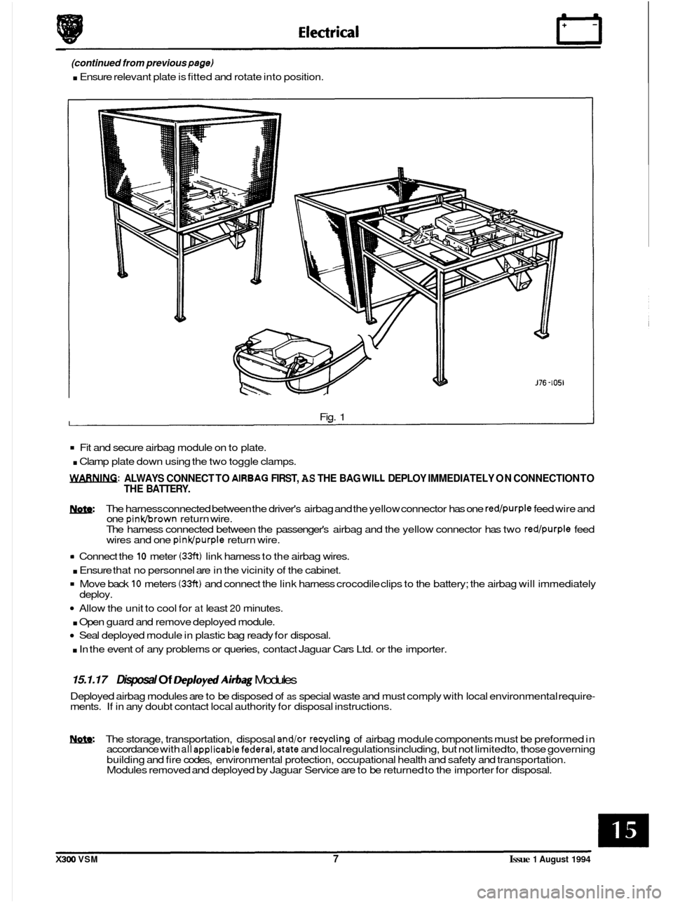
Equipment required: Deployment Cage,
IDC link harness (see 15.1.14 for details of components required), Battery,
Safety Goggles to BS 2092 grade 2 or equivalent, Rubber Gloves to PREN 374 class 2 or equivalent, Ear Protectors to BS EN 24869 or equivalent, Particulate Respirator to EN 149 grade FFP 25 or equivalent.
The deployment procedure should be performed outdoors away from other personnel.
Remove any loose debris from around airbag and ensure no flammable liquids are present.
Assemble the disposal cabinet
as shown in Fig.1 in line with the following procedures:
. Remove mesh guard from rig frame.
Attach guard to frame by bolting hinges to the frame.
(continued next page)
Modules
removedlrenewed by
Jaguar Service are to be returned to the importer for deployment and disposal.
X#w) VSM Issue 1 August 1994 6
Page 348 of 521
(continued from previous page)
. Ensure relevant plate is fitted and rotate into position.
0
Fig. 1
Fit and secure airbag module on to plate.
. Clamp plate down using the two toggle clamps.
WARNING: ALWAYS CONNECT TO AlRBAG FIRST, AS THE BAG WILL DEPLOY IMMEDIATELY ON CONNECTION TO
THE BATTERY.
m: The harness connected between the driver's airbag and the yellow connector has one red/purple feed wire and
one pinkbrown return wire.
The harness connected between the passenger's airbag and the yellow connector has two red/purple feed
wires and one pinldpurple return wire.
rn Connect the 10 meter (33ft) link harness to the airbag wires.
. Ensure that no personnel are in the vicinity of the cabinet.
Move back 10 meters (33ft) and connect the link harness crocodile clips to the battery; the airbag will immediately
Allow the unit to cool for at least 20 minutes.
. Open guard and remove deployed module.
Seal deployed module in plastic bag ready for disposal.
. In the event of any problems or queries, contact Jaguar Cars Ltd. or the importer.
deploy.
15.1.17 Disposal Of Deploytd Airbag Modules
Deployed airbag modules are to be disposed of as special waste and must comply with local environmental require- ments. If in any doubt contact local authority for disposal instructions.
W. The storage, transportation, disposal and/or recycling of airbag module components must be preformed in
accordance with all appIicablefedera1,state and local regulations including, but not limited to, those governing
building and fire codes, environmental protection, occupational health and safety and transportation.
Modules removed and deployed by Jaguar Service are to be returned to the importer for disposal.
X300 VSM 7 Issue 1 August 1994
Page 349 of 521
Electrical rl
15.2 INSTRUMENTS
15.2.1 General Description
The instruments measure, monitor and display data relevant to the vehicle’s performance. Data is received from
sensors positioned at various locations around the vehicle via two multi-pin sockets located at the rear of the
instrument panel and is than presented using three different visual display methods described as follows:
15.2.2 Analog Display
This is used to display road speed, engine speed, oil pressure, battery condition, fuel level and coolant temperature.
15.2.3 Indicator Lamps
These indicate the presence of any hazard /fault conditions or operational actions.
15.2.4 LCD (Liquid Crystal Disp/ay)
This single line, six digit seven segment display is normally used to display the odometer reading but can also be used
to display vehicle condition messages associated with particular warning lamps and trip computer information.
15.2.5 Transducers
These devices listed as follows transmit vehicle condition to the instruments:
0 Engine Coolant Temperature Transmitter
0 Low Coolant Level Probe
0 Oil Pressure Transmitter - AJ16N12
0 Fuel Gauge Tank Unit - AJlW12
Fault conditions and their causes displayed by the instruments and warning lamps are covered in more detail
by further information contained within the
Electrical Diagnostic Manual.
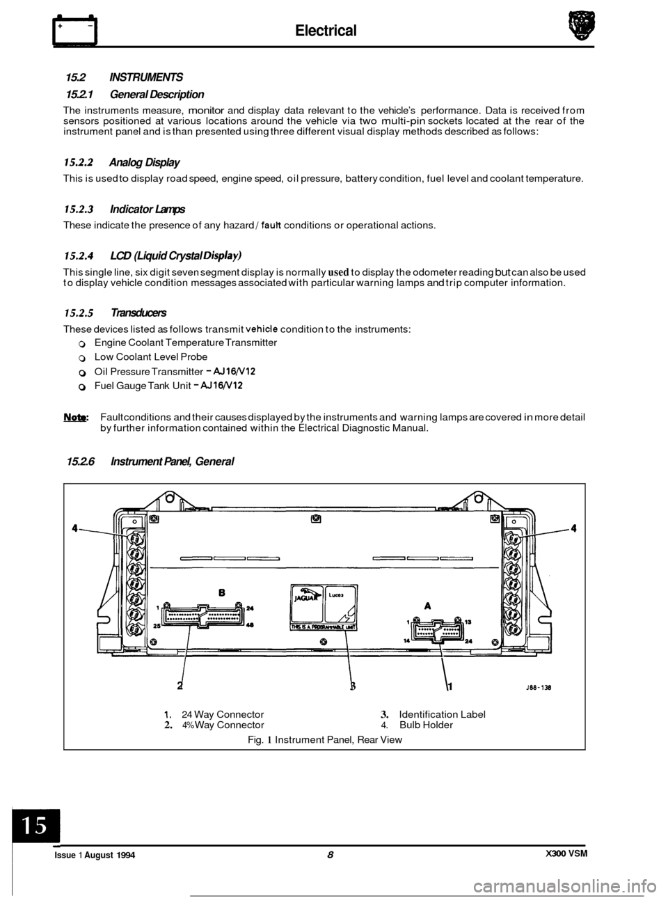
15.2.6 Instrument Panel, General
2 I I 3 1
1. 24 Way Connector 3. Identification Label 2. 4% Way Connector 4. Bulb Holder
Fig.
1 Instrument Panel, Rear View
X300 VSM Issue 1 August 1994 8
c
Page 350 of 521
31
30
29
28 27
26
4 26 24 21 23 22 7 20 19 18 18 17 8
a
10
11
12
13
14
1s
1M-137
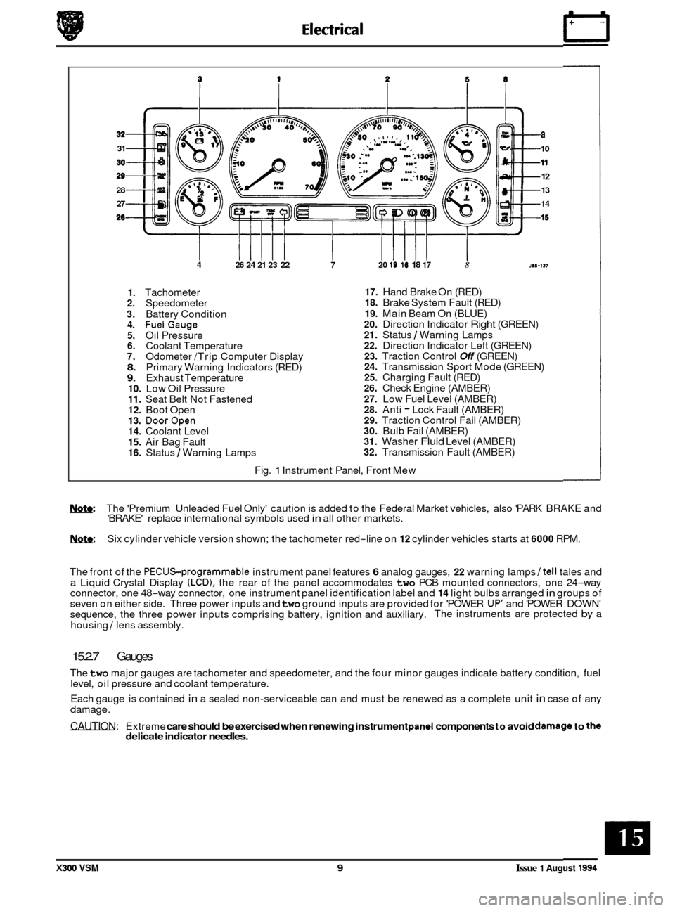
1. Tachometer 2. Speedometer
3. Battery Condition 4. FuelGauge 5. Oil Pressure 6. Coolant Temperature 7. Odometer /Trip Computer Display 8. Primary Warning Indicators (RED) 9. Exhaust Temperature 10. Low Oil Pressure 11. Seat Belt Not Fastened 12. Boot Open 13. DoorOpen 14. Coolant Level 15. Air Bag Fault 16. Status / Warning Lamps
17. Hand Brake On (RED) 18. Brake System Fault (RED)
19. Main Beam On (BLUE) 20. Direction Indicator Right (GREEN) 21. Status / Warning Lamps 22. Direction Indicator Left (GREEN) 23. Traction Control Off (GREEN) 24. Transmission Sport Mode (GREEN) 25. Charging Fault (RED) 26. Check Engine (AMBER)
27. Low Fuel Level (AMBER) 28. Anti - Lock Fault (AMBER) 29. Traction Control Fail (AMBER) 30. Bulb Fail (AMBER) 31. Washer Fluid Level (AMBER) 32. Transmission Fault (AMBER)
Fig.
1 Instrument Panel, Front Mew
w: The 'Premium Unleaded Fuel Only' caution is added to the Federal Market vehicles, also 'PARK BRAKE and
'BRAKE' replace international symbols used in all other markets.
m: Six cylinder vehicle version shown; the tachometer red-line on 12 cylinder vehicles starts at 6000 RPM.
The front of the
PECUSprogrammable instrument panel features 6 analog gauges, 22 warning lamps /tell tales and
a Liquid Crystal Display (LCD), the rear of the panel accommodates two PCB mounted connectors, one 24-way
connector, one 48-way connector, one instrument panel identification label and 14 light bulbs arranged in groups of
seven on either side. Three power inputs and two ground inputs are provided for 'POWER UP' and 'POWER DOWN'
sequence, the three power inputs comprising battery, ignition and auxiliary. The instruments are protected by a
housing
/ lens assembly.
15.2.7 Gauges
The two major gauges are tachometer and speedometer, and the four minor gauges indicate battery condition, fuel
level, oil pressure and coolant temperature.
Each gauge is contained
in a sealed non-serviceable can and must be renewed as a complete unit in case of any
damage.
CAUTION: Extreme care should be exercised when renewing instrument pand components to avoid damago to the delicate indicator needles.
X300 VSM 9 Issue 1 August 1994