JAGUAR XJ6 1994 2.G Workshop Manual
Manufacturer: JAGUAR, Model Year: 1994, Model line: XJ6, Model: JAGUAR XJ6 1994 2.GPages: 521, PDF Size: 17.35 MB
Page 371 of 521

15.11 MOTORS & SOLENOIDS ~
5.1 1.1 General
Description
Electrical
I# b
Fig. 1 Motors & Solenoids
-
1695
Fig. 1 shows a plan view of all motors located inside the trunk, the passenger compartment and the engine bay. The
motors drive various devices to perform certain functions such wipe / wash operations, window lift operations, seat
operations etc.
In order to carry out remove and refit operations, the annotated illustration is to be read in conjunction with the table
shown on the following page. This lists
all the motors and solenoids.
Some motors can be accessed by removing the various trims, the carpet, or carpet sections, other can be located
through carrying out
a visual inspection around the engine bay, the cab and the trunk.
To avoid any accidents such as electric shocks, always disconnect the battery negative lead from the battery negative
terminal before disconnecting any of the listed cables.
Issue 1 August 1994 30 X300 VSM
Page 372 of 521

Electrical rl
Key to Fig 1, Motors & Solenoids, page 36.
Filler Cap (Solenoid)
X300 VSM ~~ Issue 1 August 31
- 1994
Page 373 of 521
rl Electrical
15.12 RELAYS
15.12.1 €@ne Compartment Relays, General Description
05
04
03
02
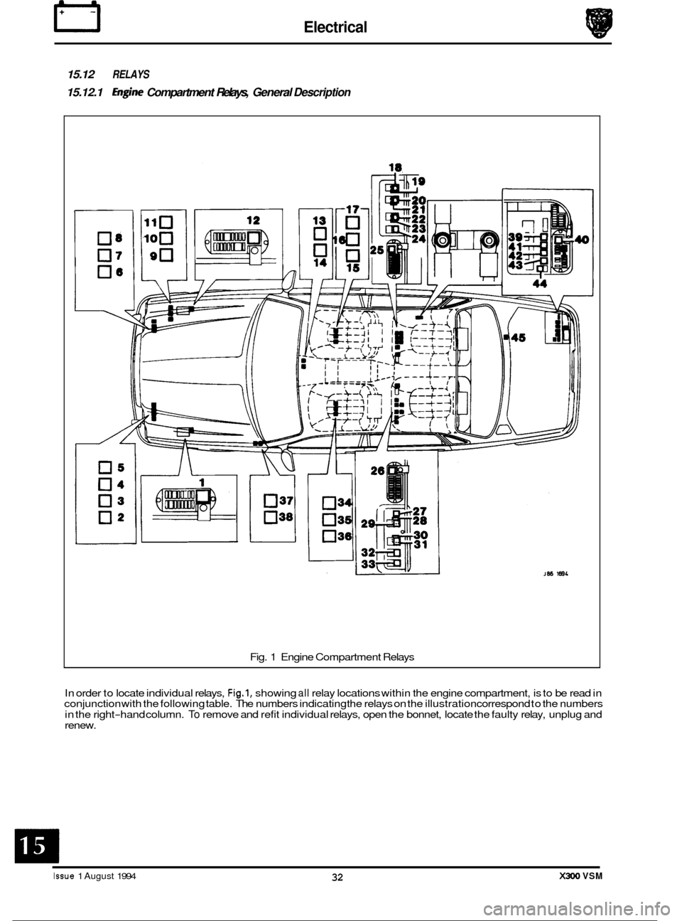
Fig. 1 Engine Compartment Relays
In order to locate individual relays,
Fig.1, showing all relay locations within the engine compartment, is to be read in
conjunction with the following table. The numbers indicating the relays on the illustration correspond to the numbers
in the right
-hand column. To remove and refit individual relays, open the bonnet, locate the faulty relay, unplug and
renew.
Issue 1 August 1994 32 X300 VSM
Page 374 of 521
Black
Black
Black All
models
All Models
All Models
Black
Black All
Models
All Models
Black/
White Stripe
Black/
White Stripe
Black Non
Aircon.
Models
only
Non Power
Wash Models
only
Optional
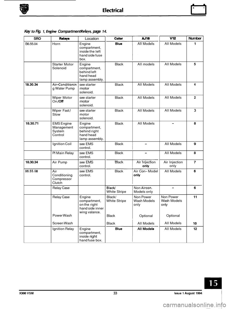
0 Key to Fig. 1, hgine Compartment Relays, page 14.
Number v12 Color
All Models
SRO
B6.55.04
Rdaw
Horn
Location
Engine
compartment,
inside the left
hand side fuse box.
Engine
compartment,
behind left hand head
lamp assembly.
see starter
motor
solenoid. All
Models
1 ~~
All
Models 5 Starter Motor
Solenoid
4 All Models
All Models 18.30.34 Air-conditionin
g Water Pump
Wiper Motor
On
/Off
2 see starter
motor
solenoid.
see starter
motor
solenoid. All
Models
3 Wiper Fast /
Slow
18.30.71 Engine
compartment, behind right
hand head
lamp assembly. 8 EMS Engine
Management
System
Control
Black
I
All Models 9 Ignition Coil
PI Main Relay see
EMS
control.
see EMS
control. Black
I
All
Models 8
Air Pump 7 see EMS
control.
see EMS
control. Black
Air Injection
Black Air Con
- Model Air
Injection
only
All Models
18.30.34
86.55.08 Air
Conditioning
Compressor
Clutch
Relay Case
Engine
compartment,
on the right
hand side inner
wing valance.
Relay
Case Non Power
Wash
Models
only
11
10
12
Power Wash
Screen Wash Optional
All Models
All Models
Black
All Models
Ignition Relay
Engine
compartment,
inside
right
hand fuse box.
X300 VSM 33 Issue 1 August 1994
Page 375 of 521
I3 E I ectr ical
'5.12.2 Passenger Compatiment Interior Relays, General Description
I 0":
03
02
I 1-
03
036 0.i
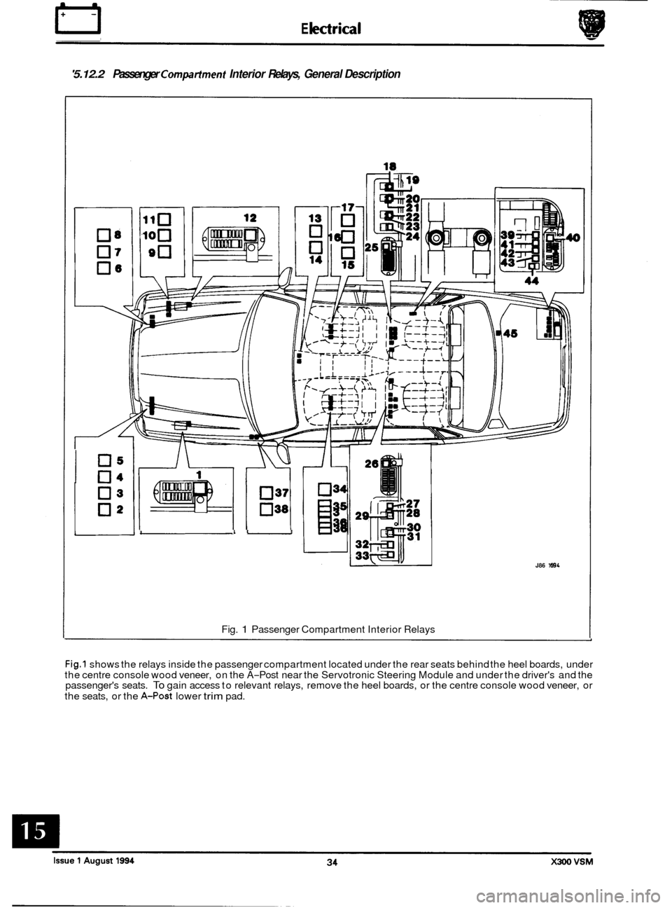
Fig. 1 Passenger Compartment Interior Relays
J86 1894
0
0
0
Fig.1 shows the relays inside the passenger compartment located under the rear seats behind the heel boards, under
the centre console wood veneer, on the A-Post near the Servotronic Steering Module and under the driver's and the
passenger's seats. To gain access to relevant relays, remove the heel boards, or the centre console wood veneer, or
the seats, or the
A-Post lower trim pad.
Page 376 of 521
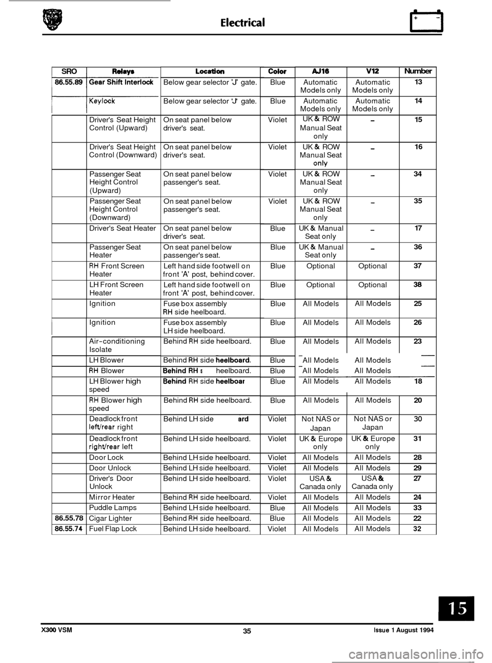
I SRO I Rdw* AJ16 v12
Automatic Automatic
Models only Models only
Automatic Automatic
Models only Models only
UK
& ROW -
Manual Seat
only
UK
& ROW -
Manual Seat
onh/
UK & ROW -
Manual Seat
only
Manual Seat
only
UK
& Manual -
Seat only
UK
& Manual -
Seat only
UK
& ROW -
Optional
Optional
Optional Optional
Keylock
Number
13
14
15
16
34
35
17
36
37
38
Driver's Seat Height
Control (Upward)
Driver's Seat Height
Control (Downward)
Passenger Seat
Height Control (Upward)
Passenger Seat
Height Control
(Downward)
Driver's Seat Heater
All Models
All Models
All Models
Passenger Seat
Heater
RH Front
Screen
Heater
LH Front Screen
Heater
Ignition All Models
25
All Models 26
All Models 23
Ignition
Air
-conditioning
Isolate
LH Blower
RH Blower
LH Blower
high
speed
RH Blower high
speed
Deadlock front
lefthear right All
Models All Models
20
Below gear selector 'J' gate.
Not NAS or
Japan
UK
& Europe
only
All Models
All Models
USA
&
Canada only
All Models
All Models
All Models
All Models
Below
gear selector
'J' gate.
Not NAS or
30
UK & Europe 31
All Models 28
All Models 29
USA & 27
All Models 24
All Models 33
All Models 22
All Models 32
Japan
only
Canada only
On
seat panel below
driver's seat.
86.55.78
86.55.74
On seat panel below
driver's seat.
Deadlock front
righthear left
Door Lock
Door Unlock
Driver's Door
Unlock
Mirror Heater
Puddle Lamps
Cigar Lighter
Fuel Flap Lock On
seat panel below
passenger's seat.
On seat panel below
passenger's seat.
On seat panel below
driver's seat.
On seat panel below
passenger's seat.
Left hand side footwell on
front
'A' post, behind cover.
Left hand side footwell on
front
'A' post, behind cover.
Fuse box assembly
RH side heelboard.
Fuse box assembly
LH side heelboard.
Behind
RH side heelboard.
Behind
RH side heelboard.
Behind RH side heelboard.
Behind
RH side heelboard.
Behind
RH side heelboard.
Behind LH side heelboard.
Behind LH side heelboard.
Behind LH side heelboard.
Behind LH side heelboard.
Behind LH side heelboard.
Behind
RH side heelboard.
Behind LH side heelboard.
Behind
RH side heelboard.
Behind LH side heelboard.
Color
Blue
Blue
Violet
Violet
Violet Violet Blue Blue
Blue
Blue
Blue
Blue
Blue
Blue
Blue Blue
Blue
Violet
Violet
Violet
Violet
Violet
Violet Blue
Blue
Violet All
Models All Models
All Models All Models
All Models All Models
18
X300 VSM 35 Issue 1 August 1994
Page 377 of 521
rl Electrical
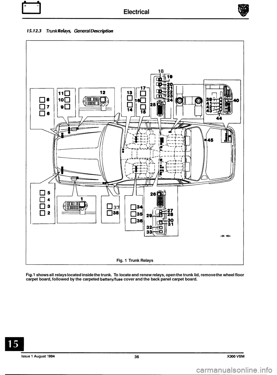
'5.12.3 Trunk Relays, General DescrptiOn
05
04
03
02
1
18
I
2-
U 37
038
Fig. 1 Trunk Relays
JW 1681
Fig.1 shows all relays located inside the trunk. To locate and renew relays, open the trunk lid, remove the wheel floor
carpet board, followed by the carpeted battery/fuse cover and the back panel carpet board.
Page 378 of 521
Electrical IT
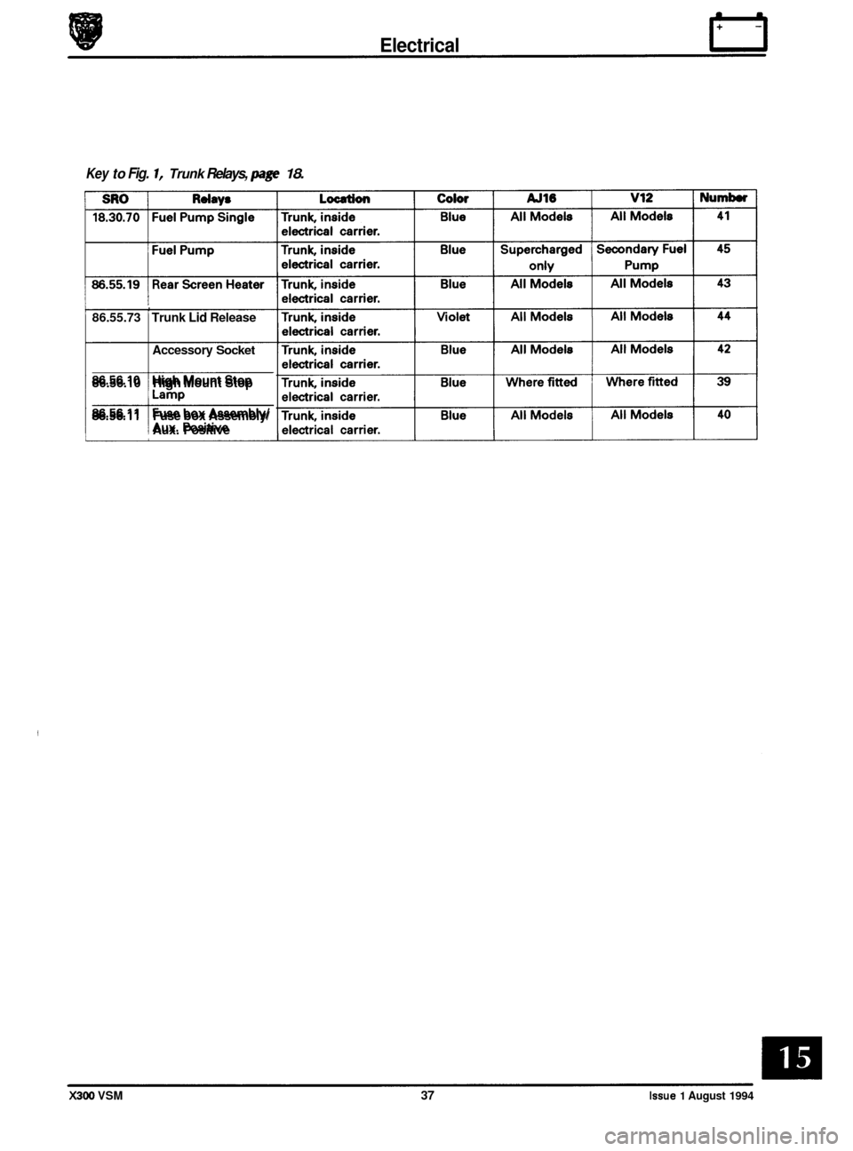
Key to Fig. 1, Trunk Relays, page 18.
, 86.55.73 Trunk Lid Release
Accessory
Socket
86.56.10 High Mount Stop
86.56.11 Fuse box Assembly/
! Aux. Positive
X300 VSM 37 Issue 1 August 1994
Page 379 of 521

rl E I ectr ical
'5.13 CONTROL MODULES (CM)
Fig. 1 Control Module Locations
15.13.1 General Description
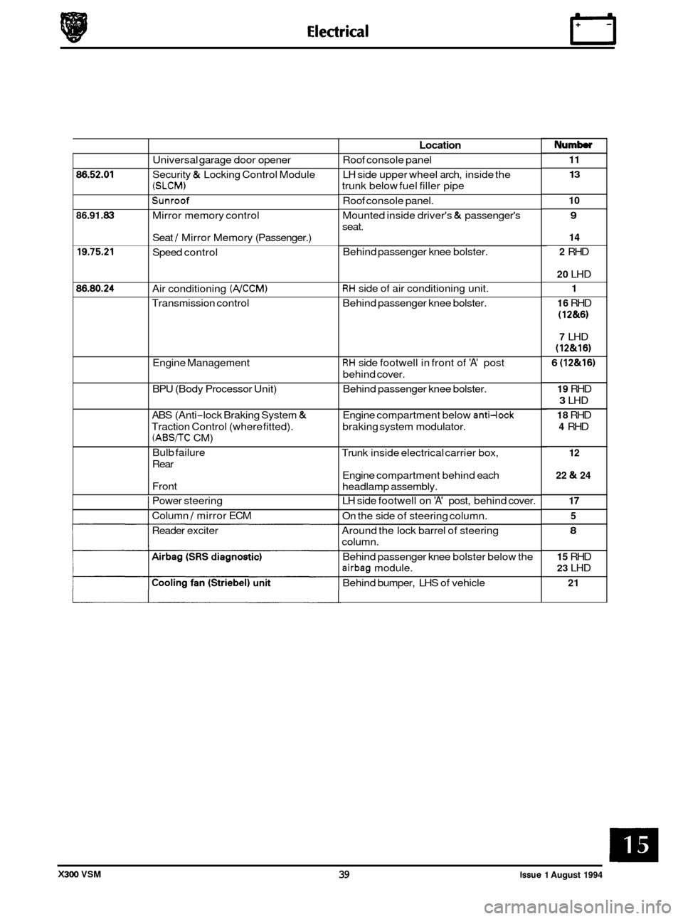
Fig. 1 shows a plan view of the control module locations for the vehicle.
In order to locate and renew modules, the illustration should be read in conjunction with the following table indicating
each module's location.
Q
0
0
Page 380 of 521
86.52.01
86.91 -83
19.75.21
86.80.24
Universal garage door opener
Security
& Locking Control Module
(SLCM)
Sunroof
Mirror memory control
Seat
/ Mirror Memory (Passenger.)
Speed control
Air conditioning
(NCCM)
Transmission control
Engine Management
BPU (Body Processor Unit)
ABS (Anti
-lock Braking System &
Traction Control (where fitted).
(ABS/TC CM)
Bulb failure
Rear
Front
I Power steering
I Column / mirror ECM
Reader exciter
Location
Roof console panel
LH side upper wheel arch, inside the
trunk below fuel filler pipe
Roof console panel.
Mounted inside driver's
& passenger's
seat.
Behind passenger knee bolster.
RH side of air conditioning unit.
Behind passenger knee bolster.
RH side footwell in front of 'A' post
behind cover.
Behind passenger knee bolster.
Engine compartment below
anti-lock
braking system modulator.
Trunk inside electrical carrier box,
Engine compartment behind each
headlamp assembly.
LH side footwell on
'A' post, behind cover.
On the side of steering column.
Around the lock barrel of steering
column.
Behind passenger knee bolster below the
airbag module.
Behind bumper, LHS of vehicle
Numb
11
13
10
9
14
2
RHD
20 LHD
1
16
RHD
(1 2&6)
7 LHD
(12&16)
6 (12&16)
19 RHD
3 LHD
18 RHD
4 RHD
12
22
& 24
17 5
8
15 RHD
23 LHD
21
X300 VSM 39 issue 1 August 1994