JAGUAR XJ6 1994 2.G Workshop Manual
Manufacturer: JAGUAR, Model Year: 1994, Model line: XJ6, Model: JAGUAR XJ6 1994 2.GPages: 521, PDF Size: 17.35 MB
Page 301 of 521
Body Components & Trim a
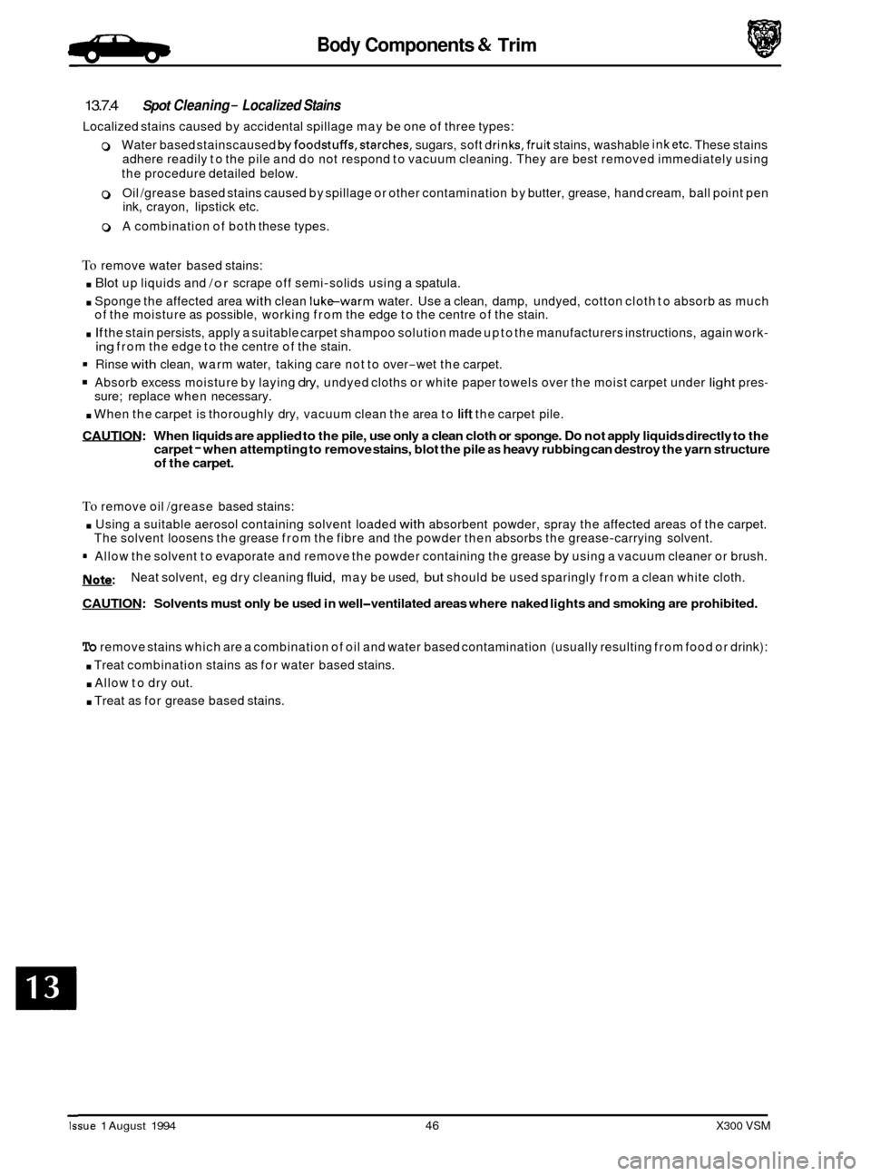
13.7.4
Localized stains caused by accidental spillage may be one of three types:
0 Water based stainscaused byfoodstuffs,starches, sugars, soft drinks,fruit stains, washable inketc. These stains
adhere readily to the pile and do not respond to vacuum cleaning. They are best removed immediately using
the procedure detailed below.
0 Oil /grease based stains caused by spillage or other contamination by butter, grease, hand cream, ball point pen
ink, crayon, lipstick etc.
0 A combination of both these types.
Spot Cleaning - Localized Stains
To remove water based stains:
. Blot up liquids and /or scrape off semi-solids using a spatula.
. Sponge the affected area with clean luke-warm water. Use a clean, damp, undyed, cotton cloth to absorb as much
. If the stain persists, apply a suitable carpet shampoo solution made up to the manufacturers instructions, again work-
= Rinse with clean, warm water, taking care not to over-wet the carpet.
Absorb excess moisture by laying dry, undyed cloths or white paper towels over the moist carpet under light pres-
. When the carpet is thoroughly dry, vacuum clean the area to lift the carpet pile.
CAUTION: When liquids are applied to the pile, use only a clean cloth or sponge. Do not apply liquids directly to the
carpet - when attempting to remove stains, blot the pile as heavy rubbing can destroy the yarn structure of the carpet.
of the moisture as possible, working from the edge to the centre of the stain.
ing from the edge to the centre of the stain.
sure; replace when necessary.
To remove oil /grease based stains:
. Using a suitable aerosol containing solvent loaded with absorbent powder, spray the affected areas of the carpet.
= Allow the solvent to evaporate and remove the powder containing the grease by using a vacuum cleaner or brush.
m:
CAUTION: Solvents must only be used in well-ventilated areas where naked lights and smoking are prohibited.
The solvent loosens the grease from the fibre and the powder then absorbs the grease-carrying solvent.
Neat solvent, eg dry cleaning
fluid, may be used, but should be used sparingly from a clean white cloth.
To remove stains which are a combination of oil and water based contamination (usually resulting from food or drink):
. Treat combination stains as for water based stains.
. Allow to dry out.
. Treat as for grease based stains.
Issue 1 August 1994 46 X300 VSM
Page 302 of 521
Body Components & Trim
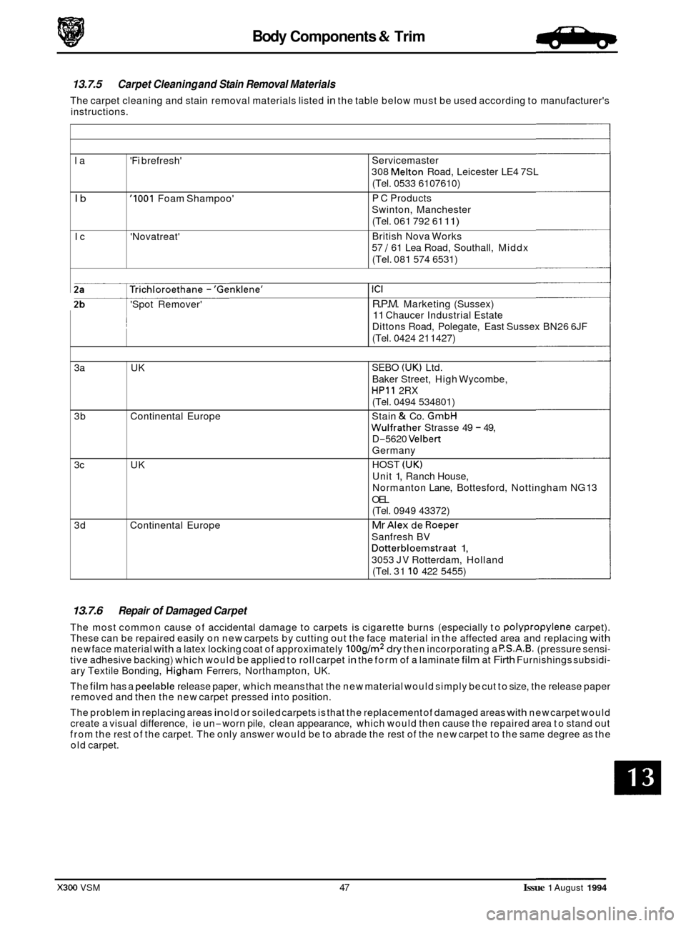
la 'Fi brefresh'
Ib '1001 Foam Shampoo'
Ic 'Novatreat'
13.7.5 Carpet Cleaning and Stain Removal Materials
The carpet cleaning and stain removal materials listed in the table below must be used according to manufacturer's
instructions.
Servicemaster
308
Melton Road, Leicester LE4 7SL
(Tel. 0533 6107610)
P C Products
Swinton, Manchester
(Tel. 061 792 61
11)
British Nova Works
57
/ 61 Lea Road, Southall, Middx
(Tel. 081 574 6531)
Trichloroethane - 'Genklene'
'Spot Remover' ~
ICI
R.P.M. Marketing
(Sussex)
11 Chaucer Industrial Estate
Dittons Road, Polegate, East Sussex BN26 6JF
(Tel. 0424 21 1427)
13.7.6 Repair of Damaged Carpet
The most common cause of accidental damage to carpets is cigarette burns (especially to polypropylene carpet).
These can be repaired easily on new carpets by cutting out the face material in the affected area and replacing with new face material with a latex locking coat of approximately 100g/m2 dry then incorporating a P.S.A.B. (pressure sensi- tive adhesive backing) which would be applied to roll carpet in the form of a laminate film at Firth Furnishings subsidi- ary Textile Bonding, Higham Ferrers, Northampton, UK.
The
film has a peelable release paper, which means that the new material would simply be cut to size, the release paper
removed and then the new carpet pressed into position.
The problem
in replacing areas in old or soiled carpets is that the replacement of damaged areas with new carpet would
create a visual difference, ie un-worn pile, clean appearance, which would then cause the repaired area to stand out
from the rest of the carpet. The only answer would be to abrade the rest of the new carpet to the same degree as the
old carpet.
3a
UK
3b Continental Europe
3c UK
3d Continental Europe
X300 VSM 47 Issue 1 August 1994
SEBO (UK) Ltd.
Baker Street, High Wycombe,
HPll 2RX
(Tel. 0494 534801)
Stain
& Co. GmbH
Wulfrather Strasse 49 - 49,
D
-5620 Velbert
Germany
HOST
(UK)
Unit 1, Ranch House,
Normanton Lane, Bottesford, Nottingham NG 13
OEL (Tel. 0949 43372)
Mr Alex de Roeper
Sanfresh BV
Dotterbloemstraat 1,
3053 JV Rotterdam, Holland
(Tel. 31
10 422 5455)
Page 303 of 521
Body Components & Trim a
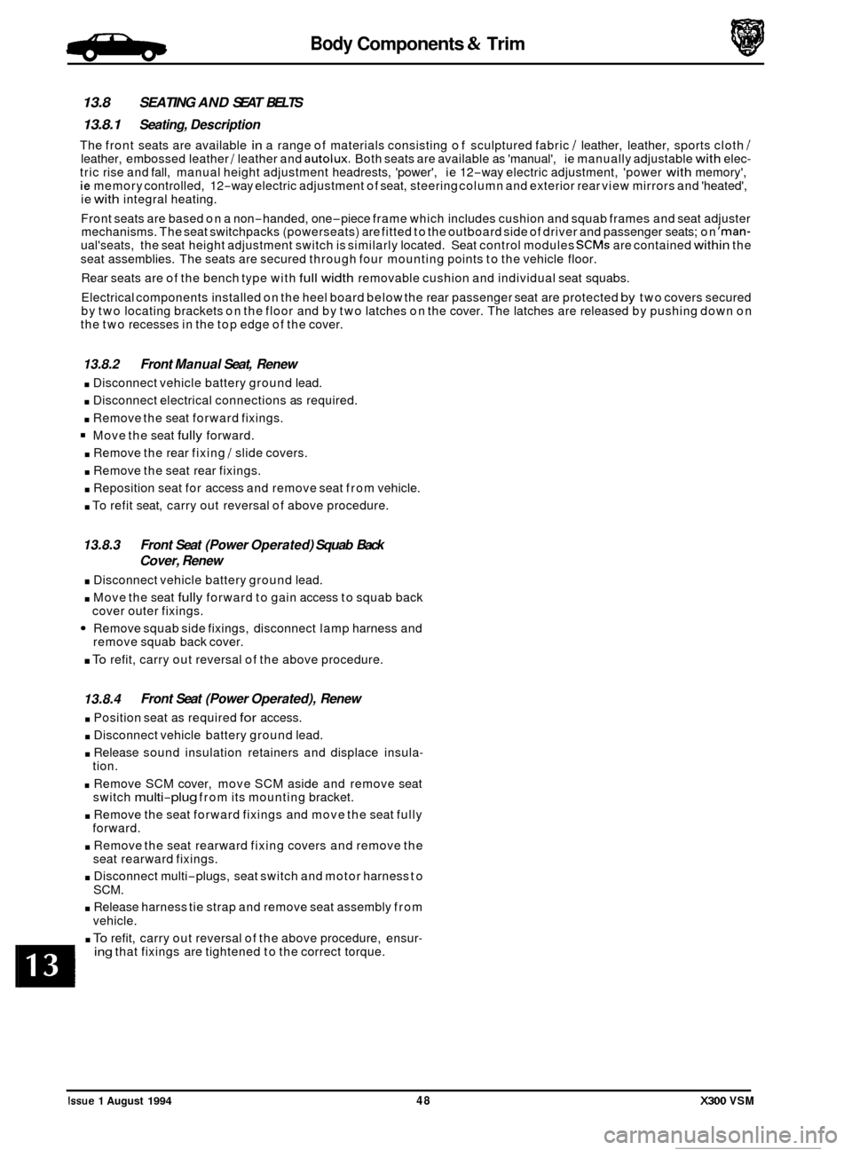
13.8 SEATING AND SEAT BELTS
13.8.1 Seating, Description
The front seats are available in a range of materials consisting of sculptured fabric / leather, leather, sports cloth / leather, embossed leather / leather and autolux. Both seats are available as 'manual', ie manually adjustable with elec- tric rise and fall, manual height adjustment headrests, 'power', ie 12-way electric adjustment, 'power with memory', ie memory controlled, 12-way electric adjustment of seat, steering column and exterior rear view mirrors and 'heated',
ie with integral heating.
Front seats are based on a non
-handed, one-piece frame which includes cushion and squab frames and seat adjuster
mechanisms. The seat switchpacks (powerseats) are fitted to the outboard side of driver and passenger seats; on 'man- ual'seats, the seat height adjustment switch is similarly located. Seat control modules SCMs are contained within the
seat assemblies. The seats are secured through four mounting points to the vehicle floor.
Rear seats are of the bench type with
full width removable cushion and individual seat squabs.
Electrical components installed on the heel board below the rear passenger seat are protected
by two covers secured
by two locating brackets on the floor and by two latches on the cover. The latches are released by pushing down on
the two recesses in the top edge of the cover.
13.8.2 Front Manual Seat, Renew
. Disconnect vehicle battery ground lead.
. Disconnect electrical connections as required.
. Remove the seat forward fixings.
Move the seat fully forward.
. Remove the rear fixing / slide covers.
. Remove the seat rear fixings.
. Reposition seat for access and remove seat from vehicle.
. To refit seat, carry out reversal of above procedure.
13.8.3
. Disconnect vehicle battery ground lead.
. Move the seat fully forward to gain access to squab back
Remove squab side fixings, disconnect lamp harness and
. To refit, carry out reversal of the above procedure.
Front Seat (Power Operated) Squab Back
Cover, Renew
cover outer fixings.
remove squab back cover.
13.8.4
. Position seat as required for access.
. Disconnect vehicle battery ground lead.
. Release sound insulation retainers and displace insula-
. Remove SCM cover, move SCM aside and remove seat
. Remove the seat forward fixings and move the seat fully
. Remove the seat rearward fixing covers and remove the
. Disconnect multi-plugs, seat switch and motor harness to
. Release harness tie strap and remove seat assembly from
Front Seat (Power Operated), Renew
tion.
switch
multi-plug from its mounting bracket.
forward. seat rearward fixings.
SCM.
vehicle.
. To refit, carry out reversal of the above procedure, ensur- ing that fixings are tightened to the correct torque.
Issue 1 August 1994 48 X300 VSM
0
0
0
Page 304 of 521
Body Components & Trim
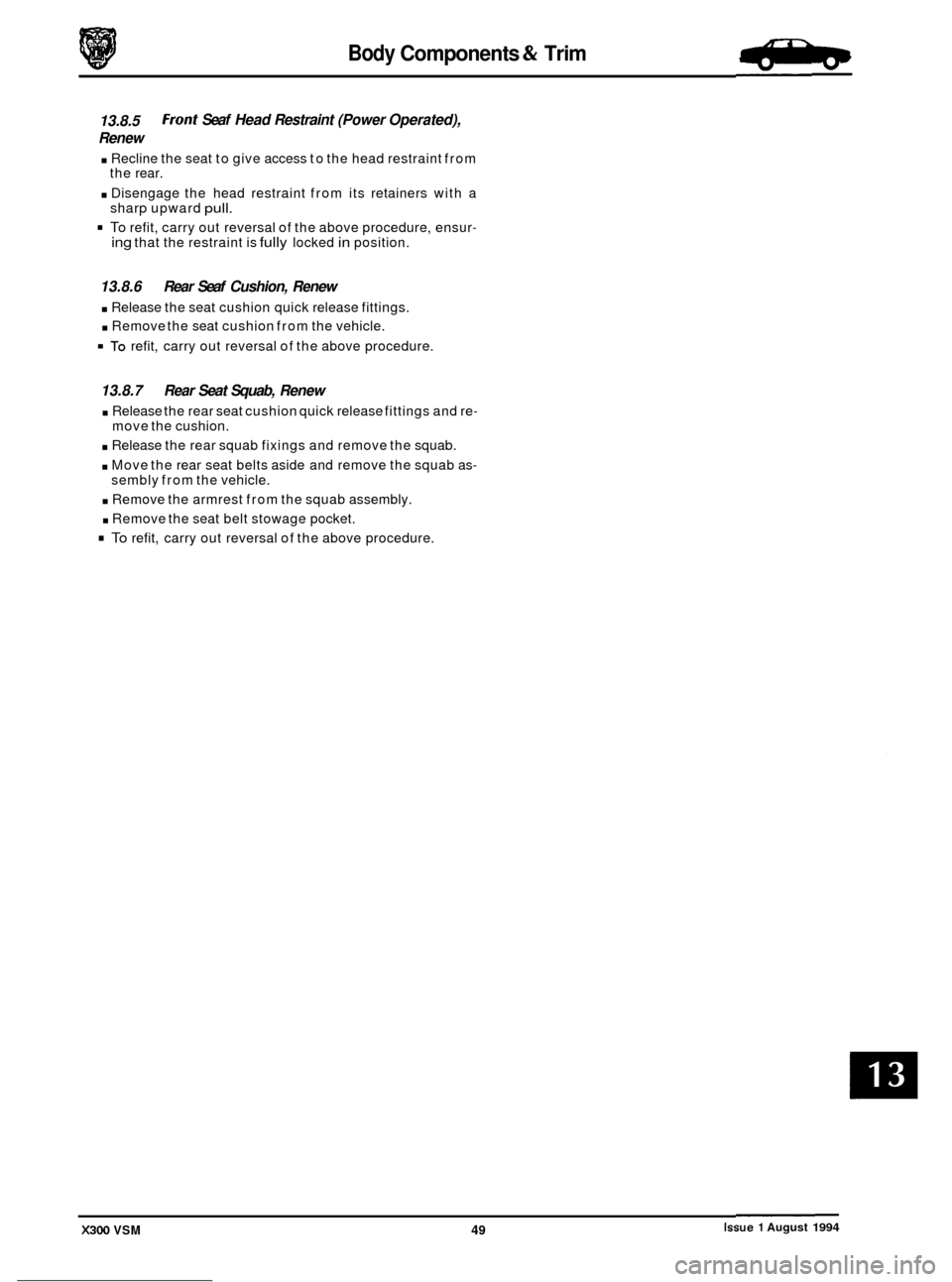
13.8.5
Renew
Front Seaf Head Restraint (Power Operated),
. Recline the seat to give access to the head restraint from
. Disengage the head restraint from its retainers with a
= To refit, carry out reversal of the above procedure, ensur-
the rear.
sharp upward
pull.
ing that the restraint is fully locked in position.
13.8.6 Rear Seaf Cushion, Renew
. Release the seat cushion quick release fittings.
. Remove the seat cushion from the vehicle.
To refit, carry out reversal of the above procedure.
13.8.7 Rear Seat Squab, Renew
. Release the rear seat cushion quick release fittings and re-
. Release the rear squab fixings and remove the squab.
. Move the rear seat belts aside and remove the squab as-
. Remove the armrest from the squab assembly.
. Remove the seat belt stowage pocket.
To refit, carry out reversal of the above procedure.
move
the cushion.
sembly from the vehicle.
Issue 1 August 1994 X300 VSM 49
Page 305 of 521
Body Components & Trim .Birpa,
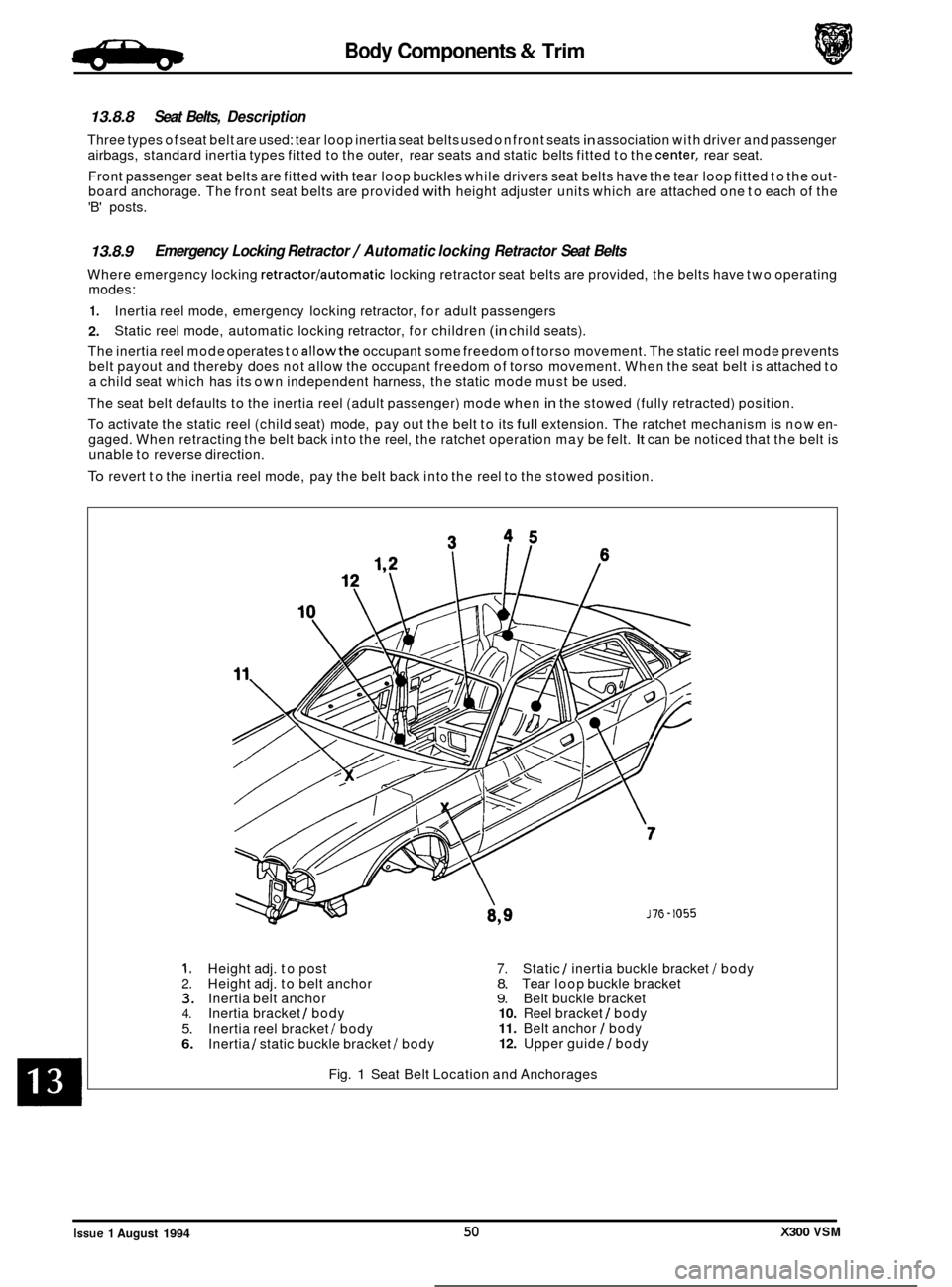
13.8.8 Seat Belts, Description
Three types of seat belt are used: tear loop inertia seat belts used on front seats in association with driver and passenger
airbags, standard inertia types fitted to the outer, rear seats and static belts fitted to the
center, rear seat.
Front passenger seat belts are fitted
with tear loop buckles while drivers seat belts have the tear loop fitted to the out- board anchorage. The front seat belts are provided with height adjuster units which are attached one to each of the
'B' posts.
13.8.9
Where emergency locking retractorlautomatic locking retractor seat belts are provided, the belts have two operating
modes:
1.
2.
The inertia reel mode operates to allowthe occupant some freedom of torso movement. The static reel mode prevents
belt payout and thereby does not allow the occupant freedom of torso movement. When the seat belt is attached to
a child seat which has its own independent harness, the static mode must be used.
The seat belt defaults to the inertia reel (adult passenger) mode when
in the stowed (fully retracted) position.
To activate the static reel (child seat) mode, pay out the belt to its
full extension. The ratchet mechanism is now en- gaged. When retracting the belt back into the reel, the ratchet operation may be felt. It can be noticed that the belt is
unable to reverse direction.
To revert to the inertia reel mode, pay the belt back into the reel to the stowed position.
Emergency Locking Retractor / Automatic locking Retractor Seat Belts
Inertia reel mode, emergency locking retractor, for adult passengers
Static reel mode, automatic locking retractor, for children
(in child seats).
1. Height adj. to post 7. Static 1 inertia buckle bracket I body 2. Height adj. to belt anchor 8. Tear loop buckle bracket 3. Inertia belt anchor 9. Belt buckle bracket 4. Inertia bracket / body 10. Reel bracket 1 body
5. 11. Belt anchor I body
6. 12. Upper guide I body
Inertia
reel bracket I body
Inertia 1 static buckle bracket I body
Fig.
1 Seat Belt Location and Anchorages
0
0
Issue 1 August 1994 50 X300 VSM
Page 306 of 521

Body Components & Trim
13.8.10 Tear loop Seat Belts, Description
The tear loop seat belt (Fig.1) is used to control the rate of forward travel of the occupant towards the deployed airbag
(the airbag is covered in Section 15, Electrical). The tear loop assembly is designed to release additional webbing when
the stitching, which retains the webbing loops, breaks under
a predetermined load. The wires (1 Fig. 1) within the as- sembly have the following functions:
0 To protect the stitching from 'normal' loads such as heavy braking or cornering.
o To control the rate of deployment.
0 To support the extended head following deployment.
When the passenger unit has been activated, the buckle will extend from the shroud and reveal
a warning label (2 Fig. 1); the extent of deployment will depend upon the severity of the load.
-: IF THE LABEL IS VISIBLE AT ALL (3 FIG. 3). THE COMPLETE ASSEMBLY MUST BE RENEWED, AS MUST
ANY SEAT BELT WHICH HAS BEEN WORN IN AN ACCIDENT.
2
Fia. 1 Tear LOOO Seat Belt
X300 VSM 51 Issue 1 August 1994 ~~
Page 307 of 521

Body Components & Trim
0 13.8.1 1 Front Seat Belt Buckle Unit, Renew
. Disconnect vehicle battery ground lead.
. Remove the front seat cushion.
. Disconnect cable connector and remove cable into seat
frame.
. Remove securing bolt, buckle unit and wavy washer.
. To refit, carry out reversal of the above procedure.
13.8.12 Front Seat Belt, Renew
. Position the front seat for access.
. Disconnect vehicle battery ground lead.
. Release 'B' post upper trim and belt aperture cover.
. Remove cover from seat belt upper fixing.
. Removeseat belt upper fixing and releaseseat belt anchor
. Lower the upper trim pad with seat belt onto the seat.
Remove 'B' post lower trim.
. Remove seat belt lower fixing, disconnect anchor plate
and remove wavy washer.
. Release upper trim pad from seat belt. Remove upper
guide fixings at 'B' post.
. Remove seat belt reel fixings and remove reel and belt as- sem bly.
. Refit seat cushion.
Secure seat belt reel to the specified torque.
Fit and secure upper guide plate to 'B' post.
Pass the seat belt through the upper trim pad.
. Fit wavy washerto lower anchor,fit lower anchor plate and
. Refit lower 'B' post trim panel.
. Refit upper 'B' post trim panel.
from
height adjuster; remove wavy washer.
0
nut; tighten to specified torque.
Place wavy washer
on height adjuster stud, fit belt upper
anchor and nut; tighten to specified torque.
. Fit plastic cover and split finisher.
13.8.13 Rear Inertia Seat Belt, Renew
= Remove seat cushion, rear seat squab and rear parcel tray.
. Remove foam pad from rear shelf and remove seat belt
. Remove buckle assembly, washers and spacers.
. Remove side seat belt buckle and the lower anchorage
. Move the belt aside and remove the upper spacer.
Remove theseat belt bracket/ body fixing and remove reel
= Remove seat belt reel / securing bracket fixings.
. Remove the reel and belt assembly.
. To refit, carry out reversal of the above procedure.
0 buckle bolt.
belt.
/ bracket assembly.
m
Issue 1 August 1994 52 X300 VSM ~~
Page 308 of 521
Body Components & Trim -
0 13.8.14 Rear, Center, Static Seat Belt, Renew
Remove rear seat cushion.
Remove seat belt buckle bolt and remove buckle.
Remove washers, spacers and side seat belt buckle.
Remove
center lap strap buckle and seat belt strap secur- ing bolt.
Remove the strap and buckle assembly.
Remove washers, spacers and side seat belt buckle.
To refit, carry out reversal of the above procedure.
X300 VSM 53 Issue 1 August 1994
Page 309 of 521

54
Page 310 of 521
Climate Control Systems
SECTION CONTENTS
Subsection Title SRO Page
i to iii ............ Preliminary Pages ................................................................ i to iii
14.1
............. Working Practices .................................................................... 1
Working Practices. General ............................................................ 1 14.1.1 ............
14.1.2. ........... Working Practices. Handling Refrigerant ................................................. 1
14.1.3 ............ Working Practices. Handling Lubricating Oil ............................................. 2
14.1.4
............ Working Practices. System Maintenance ................................................. 2
14.2
............. Climate ControlSystem ............................................................... 3
14.2.1
............ Climate Control System. Description .................................................... 3
14.2.2.
........... Climate Control System. Features ....................................................... 3
14.3
............. ClimateControl Panel ................................................................ 4
14.4
.............
14.4.1 ............ Temperature Control. Coolant Circuit .................................................... 6
14.5 ............. Air Conditioning Control Module ....................................................... 7
14.5.1 ............ Air Conditioning Control Module. Description 7
14.5.2. ........... Air Conditioning Control Module. Interfaces .............................................. 8
14.6
............. Control Module Fault & Condition Self-Analysis .......................................... 9
14.6.1
............ Control Module Fault & Condition Self-Analysis. System Health ............................. 9
14.6.2.
........... Control Module Fault & Condition Self-Analysis. System Protection .......................... 9
14.7
............. Air Distribution ..................................................................... 10
14.8
............. Refrigeration Cycle .................................................................. 12
14.9
............. General System Procedures ........................................................... 13
14.9.1
............ General System Procedures. Leak Test .................................................. 13
14.9.2
............ General System Procedures. Charge Recovery (System Depressurization) .................... 13
14.9.3.
........... General System Procedures. Evacuating the System ....................................... 13
14.9.4.
........... General System Procedures. Adding Lubricating Oil (Compressor Related) ................... 13
14.9.5.
........... General System Procedures. Adding Lubricating Oil (Component Related) ................... 14
14.9.6.
........... General System Procedures. Adding Refrigerant .......................................... 14
14.10
............ Fault Diagnosis ..................................................................... 15
14.10.1
.......... Fault Diagnosis. Introduction .......................................................... 15
14.10.2
.......... FaultDiagnosis. FunctionalCheck ..................................................... 15
14.10.3
14.11
............ Systemself- Test .................................................................... 17
14.1 1.1 ........... System Self- Test. Interrogation Procedure via the Control Panel ............................ 17
14.1 1.2 ........... System Self- Test. Control Panel Fault Code Key ......................................... 17
14.1 1.4 ........... System Self- Test. Panel Communication Check .......................................... 18
14.13
............ System Checking With Manifold Gauge Set ............................................. 20
14.7 3.1 .......... System Checking With Manifold Gauge Set. Evacuating the Gauge Set ...................... 20
14.13.2 .......... System Checking With Manifold Gauge Set. Connecting the Manifold Gauge Set .............. 20
14.13.3
.......... System Checking With Manifold Gauge Set. Stabilizing the System ......................... 20
14.14
............ Pressure / Temperature Graph (High Side / Ambient Temperature) ........................... 21
14.15
............ Pressure / Temperature Graph (Low Side / Evaporator Temperature) ......................... 22
14.16
............ System Pressure Fault Classification ................................................... 23
Temperature
Control
.................................................................. 6
............................................ a
.......... Fault Diagnosis. System Symptoms ..................................................... 15 a
14.1 1.3 ........... System Self- Test. Associated Faults .................................................... 18
14.12
............ Manifold Gauge Set ................................................................. 19
X300 VSM ~ i Issue 1 August 1994