JAGUAR XJ6 1994 2.G Workshop Manual
Manufacturer: JAGUAR, Model Year: 1994, Model line: XJ6, Model: JAGUAR XJ6 1994 2.GPages: 521, PDF Size: 17.35 MB
Page 331 of 521
Climate Control Systems
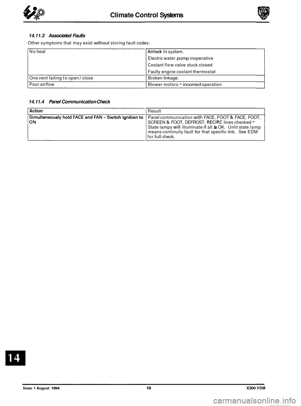
No heat
One vent failing to open
/ close
Poor airflow
14.11.3 Associated Faults
Other symptoms that may exist without storing fault codes:
Airlock in system.
Electric water
pump inoperative
Coolant flow valve stuck closed
Faulty engine coolant thermostat
Broken linkage.
Blower motors
- incorrect operation
14.11.4 Panel Communication Check
Action Result
Panel communication
with FACE, FOOT & FACE, FOOT,
SCREEN
& FOOT, DEFROST, RECIRC lines checked - State lamps will illuminate if all is OK. Unlit state lamp
means continuity fault for that specific link. See EDM
for
full check.
0
0
0
Issue 1 August 1994 18 X300 VSM
Page 332 of 521
Climate Control Systems
14.12 MANIFOLD GAUGESET
The manifold gauge set is a most important tool fortracing faults and system efficiency assessment. The relationship
to each other of HIGH and LOW pressures and their correlation to AMBIENT and EVAPORATOR temperatures must be
compared to determine system status (see Pressure /Temperature graphs in Sub
-Sections 14.14 & 14.15).
Because of the heavy reliance upon this piece of equipmentfor service diagnosis, ensure that the gauges are calibrated
regularly and the equipment is treated
with care.
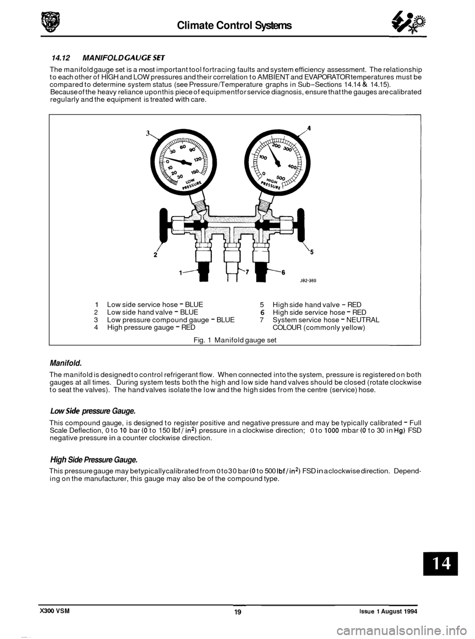
3
1 Low side service hose - BLUE
5 High side hand valve - RED 2 Low side hand valve - BLUE 6 High side service hose - RED
3 Low pressure compound gauge - BLUE 7 System service hose - NEUTRAL
4 High pressure gauge - RED
COLOUR (commonly yellow)
Fig. 1 Manifold gauge set
Manifold.
The manifold is designed to control refrigerant flow. When connected into the system, pressure is registered on both
gauges at all times. During system tests both the high and low side hand valves should be closed (rotate clockwise
to seat the valves). The hand valves isolate the low and the high sides from the centre (service) hose.
0 Low side pressure Gauge.
This compound gauge, is designed to register positive and negative pressure and may be typically calibrated - Full
Scale Deflection, 0 to 10 bar (0 to 150 Ibf / in2) pressure in a clockwise direction; 0 to 1000 mbar (0 to 30 in Hg) FSD
negative pressure in a counter clockwise direction.
High Side Pressure Gauge.
This pressure gauge may betypicallycalibrated from 0 to30 bar (0 to 500 Ibf/in2) FSD in a clockwise direction. Depend-
ing on the manufacturer, this gauge may also be of the compound type.
X300 VSM Issue 1 August 1994
Page 333 of 521
Climate Control Systems
14.13 SYSTEM CHECKING WITH MANIFOLD GAUGE Sm
14.13.1 Evacuating the Manifold Gauge Set
Attach the centre (service) hose to a vacuum pump and start the pump. Open fully both high anddow valves and allow
the vacuum to remove air and moisture from the manifold set for at least five minutes.
Turn the vacuum pump off and isolate it from the centre service hose but do not open the hose to atmosphere.
CAUTION: It is imperative that the vacuum pump is not subjected to a positive pressure of any degree. Therefore
the pump must be frtted with an isolation valve at the centre (service hose) connection and this valve
must be closed before the pump is switched off. This operation replaces the 'purge' procedure used on
previous systems. Observe the manufacturefs recommendation with regard to vacuum pump oil
changes.
14.13.2 Connecting the Manifold Gauge Set
CAUTION: Only use hoses with connectors which are dedicated to HFC 134A charge ports.
Attachment of the hose quick release connectors to the high and low side system ports is straightfotward, provided
that the high and low valves are closed and the system is NOT operational.
Assessment of system operating efficiency and fault classification may be achieved by using the facilities on your
Re- covery / Recharging / Recycling station, follow the manufacturers instructions implicitly and observe all safety con- siderations.
WARNING: UNDER NO CIRCUMSTANCES SHOULD THE CONNECTIONS BE MADE WITH THE SYSTEM IN
OPERATION OR THE VALVES OPEN. SHOULD THE VALVES BE OPEN AND A VACUUM PUMP OR
REFRIGERANT CONTAINER ATTACHED, AN EXPLOSION COULD OCCUR AS A RESULT OF HIGH
PRESSURE REFRIGERANT BEING FORCED BACK INTO THE VACUUM PUMP
OR CONTAINER.
14.13.3 Stabilizing the System
Accurate test gauge data will only be attained if the system temperatures and pressures are stabilized.
Ensure that equipment and hoses cannot come into contact with engine moving parts or sources of heat.
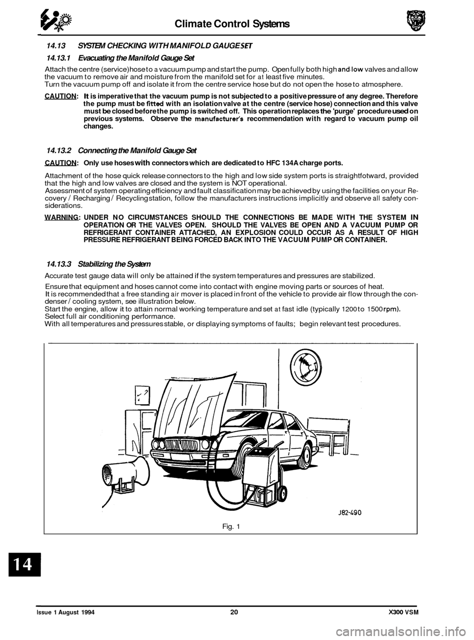
It is recommended that a free standing air mover is placed in front of the vehicle to provide air flow through the con- denser / cooling system, see illustration below.
Start the engine, allow
it to attain normal working temperature and set at fast idle (typically 1200 to 1500 rpm). Select full air conditioning performance.
With all temperatures and pressures stable, or displaying symptoms of faults; begin relevant test procedures.
Fig.
1
Issue 1 August 1994 20 X300 VSM
Page 334 of 521
Climate Control Systems
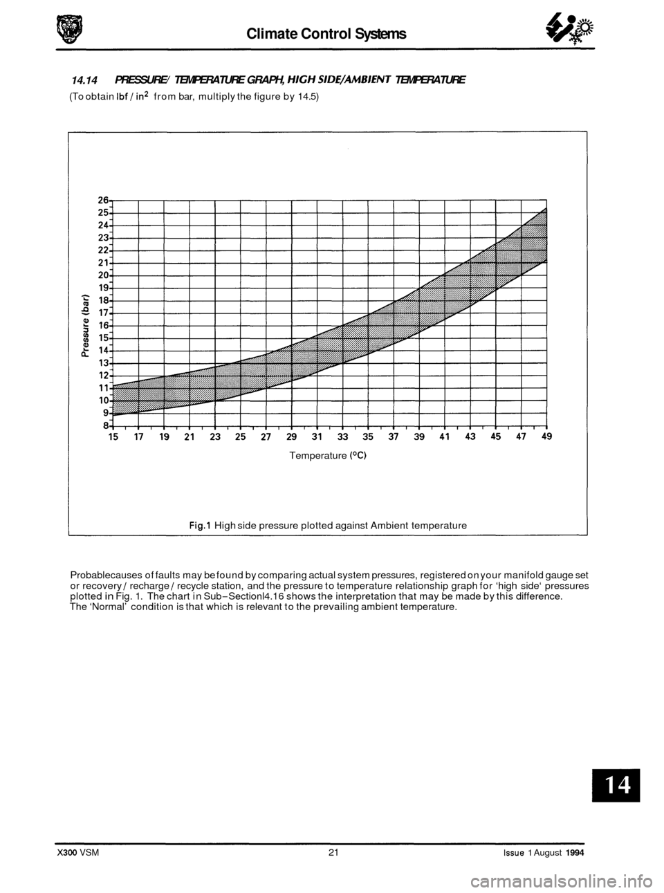
14.14 PRESSURE/ TEMPERATURE GRAPH, HIGH SIDE/AMBIENT TEMPERATURE
(To obtain Ibf / in2 from bar, multiply the figure by 14.5)
Temperature
(OC)
Fig.1 High side pressure plotted against Ambient temperature
0 Probablecauses of faults may be found by comparing actual system pressures, registered on your manifold gauge set
or recovery
/ recharge / recycle station, and the pressure to temperature relationship graph for ‘high side‘ pressures
plotted in Fig. 1. The chart in Sub-Sectionl4.16 shows the interpretation that may be made by this difference.
The ‘Normal’ condition is that which is relevant to the prevailing ambient temperature.
X300 VSM 21 Issue 1 August 1994
Page 335 of 521
Climate Control Systems
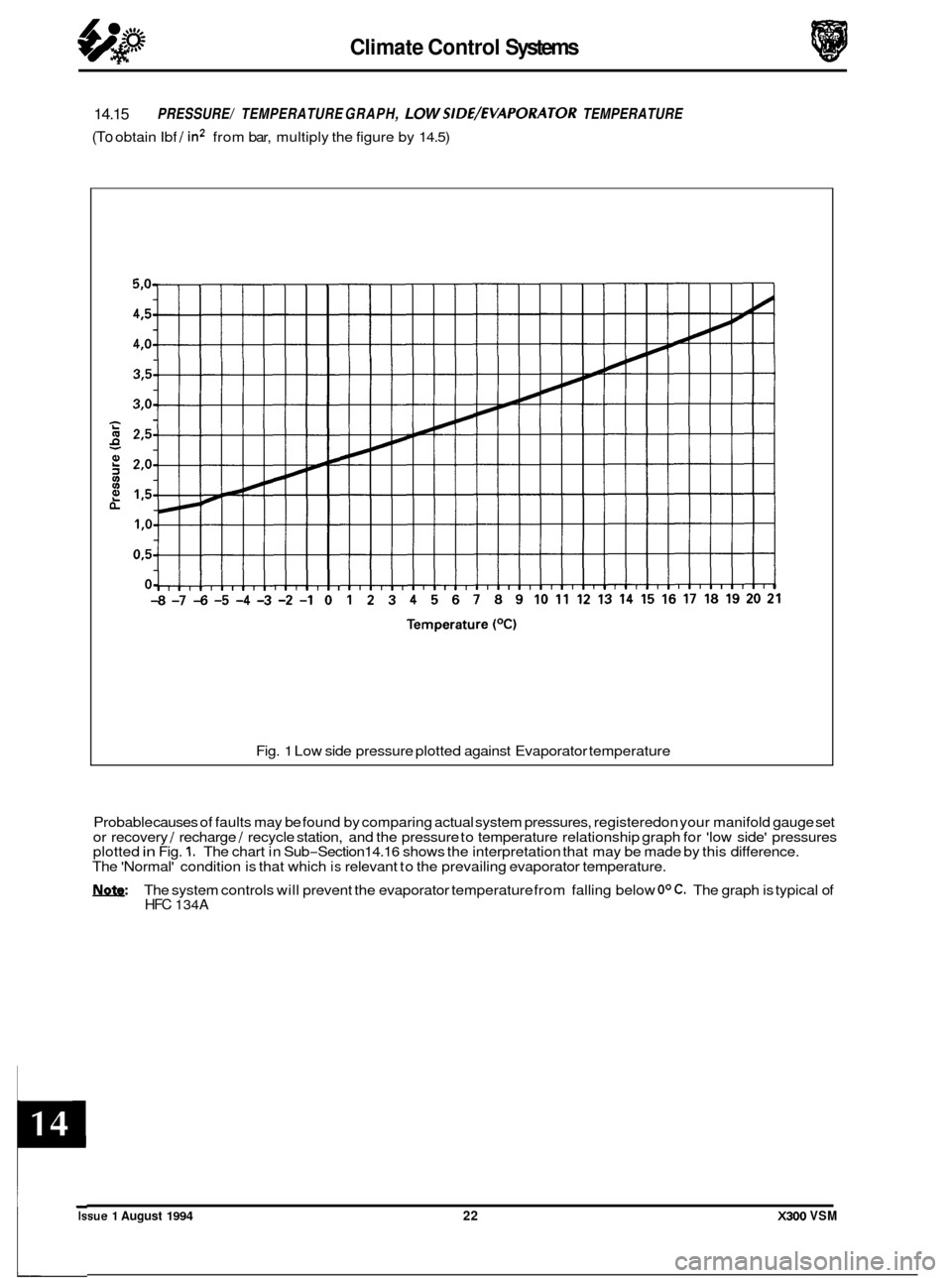
14.15
(To obtain Ibf / in2 from bar, multiply the figure by 14.5)
PRESSURE/ TEMPERATURE GRAPH, LOW SIDE/EVAPORATOR TEMPERATURE
Fig. 1 Low side pressure plotted against Evaporator temperature
Probable causes of faults may be found by comparing actual system pressures, registered on your manifold gauge set
or recovery
/ recharge / recycle station, and the pressure to temperature relationship graph for 'low side' pressures
plotted in Fig. 1. The chart in Sub-Section14.16 shows the interpretation that may be made by this difference.
The 'Normal' condition is that which is relevant to the prevailing evaporator temperature.
The system controls will prevent the evaporator temperature from falling below
OOC. The graph is typical of HFC 134A
0
0
0
Issue 1 August 1994 22 X300 VSM
Page 336 of 521
Climate Control Systems
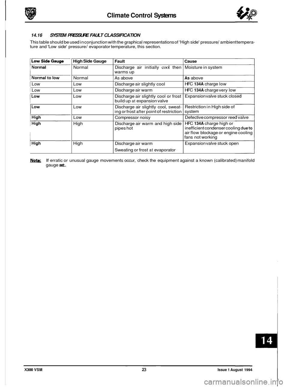
High Side Gauge
Normal
@ 14.16 SYSTEM PRESSURE FAULT CLASSIFICATION
This table should be used in conjunction with the graphical representations of 'High side' pressure / ambient tempera- ture and 'Low side' pressure / evaporator temperature, this section.
Fault Cause
Discharge air initially cool then Moisture in system
warms up
1 Low Normal
Low
Low
Low
Low
I Low
As above As above
Discharge air slightly cool HFC
134A charge
low
Discharge air warm HFC
134A charge very low
Discharge air slightly cool or frost Expansion valve
stuck closed
build up
at expansion valve
Discharge air slightly cool, sweat
- Restriction in High side of
ing or frost
after point of restriction system
I
Low
High
High
I
Compressor noisy Defective compressor
reed valve
Discharge air warm and high side HFC
134A charge
high or
pipes hot inefficient
condenser cooling
dueto
air flow blockage or engine cooling
fans not working
Expansion valve stuck open
Discharge air warm
Sweating or frost
at evaporator
If erratic or unusual gauge movements occur, check the equipment against a known (calibrated) manifold
gauge
set. ~ ~~~
X300 VSM 23 Issue 1 August 1994
Page 337 of 521

24
Page 338 of 521
Electrical cl
.
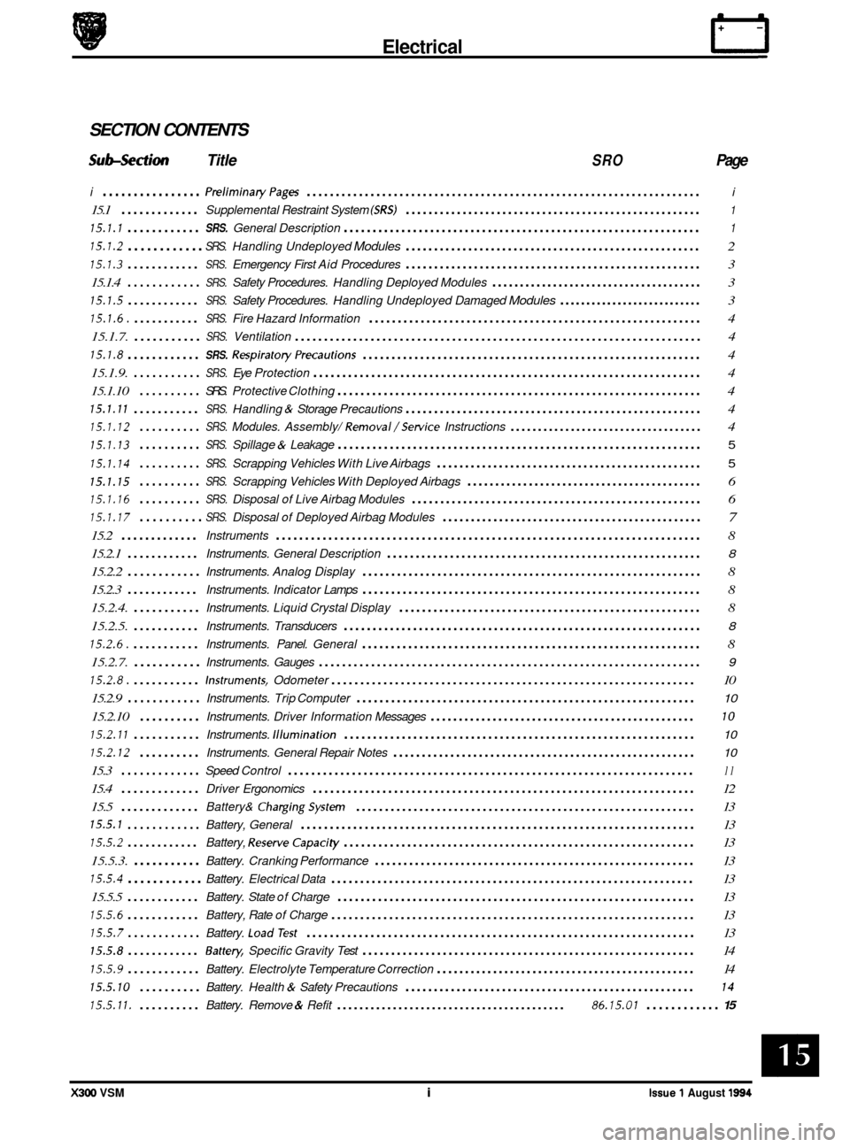
SECTION CONTENTS
Subsection Title SRO Page
i ................ PreliminaryPages .................................................................... i
15.1 ............. Supplemental Restraint System (SRS) .................................................... 1
15.1.1 ............ SRS. General Description .............................................................. 1
15.1.2 ............ SRS. Handling Undeployed Modules .................................................... 2
15.1.3 ............ SRS. Emergency First Aid Procedures .................................................... 3
15.1.4
............ SRS. Safety Procedures. Handling Deployed Modules ...................................... 3
15.1.5 ............ SRS. Safety Procedures. Handling Undeployed Damaged Modules ........................... 3
15.1.6. ........... SRS. Fire Hazard Information .......................................................... 4
15.1.7.
........... SRS. Ventilation ...................................................................... 4
15.1.8 ............ SRS. RespiratoryPrecautions ........................................................... 4
15.1.9.
........... SRS. Eye Protection ................................................................... 4
15.1.10
.......... SRS. Protective Clothing ............................................................... 4
15.1.11 ........... SRS. Handling & Storage Precautions .................................................... 4
15.1.12 .......... SRS. Modules. Assembly/ Removal/Setvice Instructions ................................... 4
15.1.13 .......... SRS. Spillage & Leakage ............................................................... 5
15.1.14 .......... SRS. Scrapping Vehicles With Live Airbags ............................................... 5
15.1.15 .......... SRS. Scrapping Vehicles With Deployed Airbags .......................................... 6
15.1.16 .......... SRS. Disposal of Live Airbag Modules ................................................... 6
15.1.17 .......... SRS. Disposal of Deployed Airbag Modules .............................................. 7
15.2 ............. Instruments ........................................................................\
. 8
15.2.1
............ Instruments. General Description ....................................................... 8
15.2.2 ............ Instruments. Analog Display ........................................................... 8
15.2.3
............ Instruments. Indicator Lamps ........................................................... 8
15.2.4.
........... Instruments. Liquid Crystal Display ..................................................... 8
15.2.5.
........... Instruments. Transducers .............................................................. 8
15.2.6. ........... Instruments. Panel. General ........................................................... 8
15.2.7.
........... Instruments. Gauges .................................................................. 9
15.2.8. ........... Instruments. Odometer ............................................................... 10
15.2.9
............ Instruments. Trip Computer ........................................................... 10
15.2.10 .......... Instruments. Driver Information Messages ............................................... 10
15.2.11 ........... Instruments. Illumination ............................................................. 10
15.2.12 .......... Instruments. General Repair Notes ..................................................... 10
15.3 ............. Speed Control ...................................................................... 11
15.4 ............. Driver Ergonomics .................................................................. 12
15.5
............. Battery& ChargingSystem ........................................................... 13
15.5.1 ............ Battery, General .................................................................... 13
15.5.2 ............ Battery, ReserveCapaci ty ............................................................. 13
15.5.3.
........... Battery. Cranking Performance ........................................................ 13
15.5.4 ............ Battery. Electrical Data ............................................................... 13
15.5.5
............ Battery. State of Charge .............................................................. 13
15.5.6 ............ Battery, Rate of Charge ............................................................... 13
15.5.7 ............ Battery. LoadTest ................................................................... 13
15.5.8 ............ Battey. Specific Gravity Test .......................................................... 14
15.5.9 ............ Battery. Electrolyte Temperature Correction .............................................. 14
15.5.10 .......... Battery. Health & Safety Precautions ................................................... 14
15.5.11. .......... Battery. Remove & Refit ......................................... 86.15.01 ............ 15
e
e
X300 VSM i Issue 1 August 1994
Page 339 of 521
rl Electrical
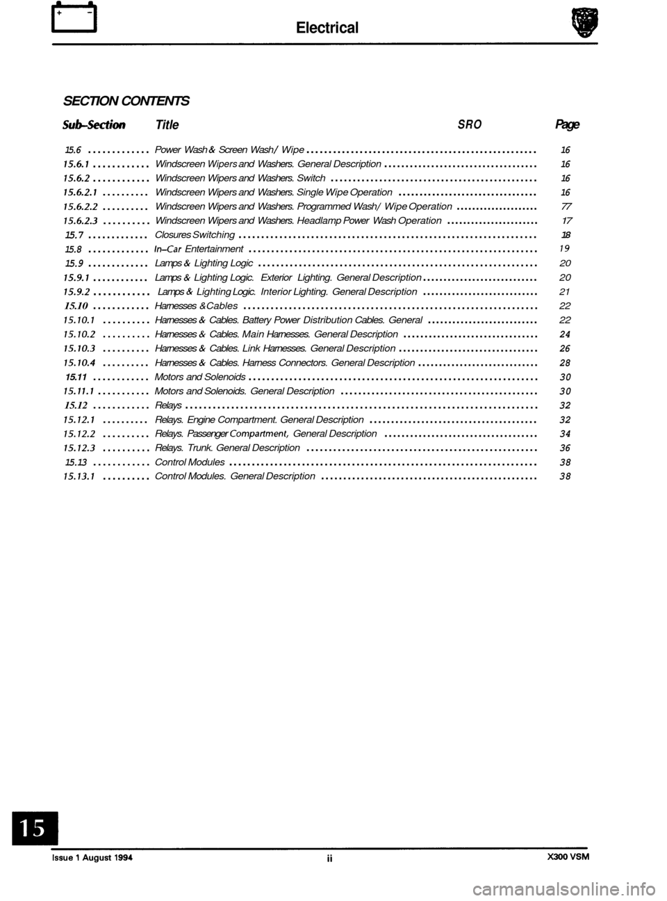
SECTION CONTENTS
Sub-section Title SRO Page
15.6 .............
15.6.1 ............
15.6.2 ............
15.6.2.1 ..........
15.6.2.2 ..........
15.6.2.3 ..........
15.7 .............
15.8 .............
15.9 .............
15.9.1 ............
15.9.2 ............
15.10 ............
15.10.1 ..........
15.10.2 ..........
15.10.3 ..........
15.10.4 ..........
15.11 ............
15.11.1 ...........
15.12 ............
15.12.1 ..........
15.12.2 ..........
15.12.3 ..........
15.13 ............
15.13.1 ..........
Power Wash & Screen Wash / Wipe .................................................... 16
Windscreen Wipers and Washers. General Description .................................... 16
Windscreen Wipers and Washers. Switch ............................................... 16
Windscreen Wipers and Washers. Single Wipe Operation ................................. 16
Windscreen Wipers and Washers. Programmed Wash / Wipe Operation ..................... 77
Windscreen Wipers and Washers. Headlamp Power Wash Operation ....................... 17
Closures Switching .................................................................. 18
In-Car Entertainment ................................................................ 19
Lamps & Lighting Logic .............................................................. 20
Lamps & Lighting Logic. Exterior Lighting. General Description ............................ 20
Lamps & Lighting Logic. Interior Lighting. General Description ............................ 21
Harnesses &Cables ................................................................. 22
Harnesses
& Cables. Battery Power Distribution Cables. General ........................... 22
Harnesses & Cables. Main Harnesses. General Description ................................ 24
Harnesses & Cables. Link Harnesses. General Description ................................. 26
Harnesses & Cables. Harness Connectors. General Description ............................. 28
Motors and Solenoids ................................................................ 30
Motors and Solenoids. General Description ............................................. 30
Relays ........................................................................\
..... 32
Relays. Engine Compartment. General Description ....................................... 32
Relays. Passenger Compartment. General Description .................................... 34
Relays. Trunk. General Description .................................................... 36
Control Modules .................................................................... 38
Control Modules. General Description ................................................. 38
Page 340 of 521
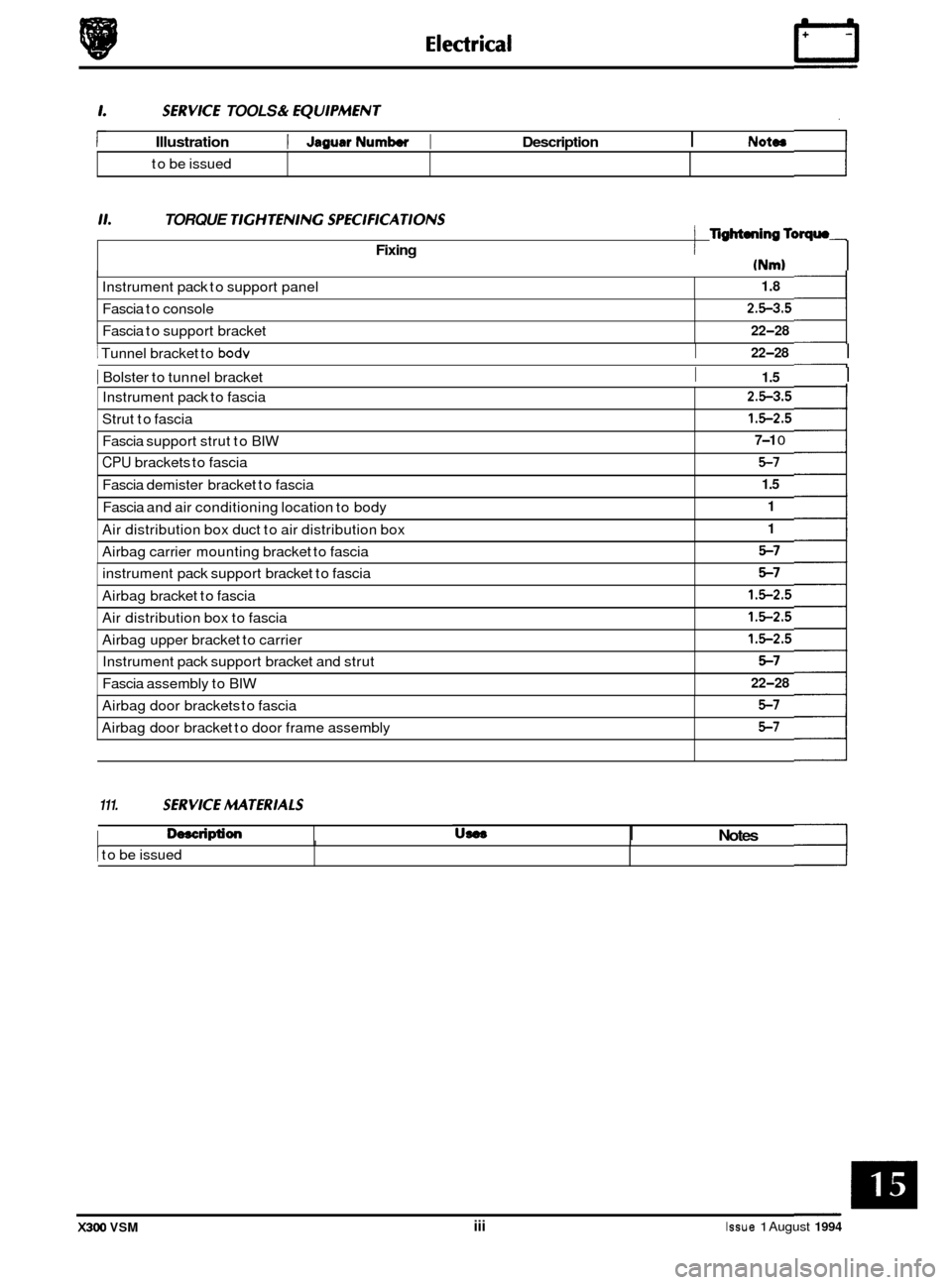
SERVKE TOOLS & EQU1PMENT
Illustration I JagusrNumbw I Description I NOtOS
Instrument pack to support panel
to
be issued
11. TORQUE TlGHTENlNG SPEC1FKATIONS
1.8
Fixing
Fascia to console
Fascia to support bracket
(Nm)
I TigM.ningToqrn
I
2.5-3.5
22-28
Instrument pack to fascia
Strut to fascia 2.5-3.5
1.5-2.5
I I 22-28 1 Tunnel bracket to bodv
I Bolster to tunnel bracket I 1.5 I
Fascia support strut to BIW 7-1 0
CPU brackets to fascia 5-7
Fascia demister bracket to fascia 1.5
Fascia and air conditioning location to body 1
Air distribution box duct to air distribution box
Airbag carrier mounting bracket to fascia 1
5-7
instrument pack support bracket to fascia
Airbag bracket to fascia 5-7
1.5-2.5
Air distribution box to fascia
Airbag upper bracket to carrier 1.5-2.5
1.5-2.5
Instrument pack support bracket and strut
Fascia assembly to BIW 5-7
22-28
111. SERVKE MTERlALS
0, Description
Airbag door brackets to fascia
Airbag door bracket to door frame assembly 5-7
5-7
US08 Notes I I
1 to be issued I I
X300 VSM iii Issue 1 August 1994