electrical JAGUAR XJ6 1994 2.G Owner's Guide
[x] Cancel search | Manufacturer: JAGUAR, Model Year: 1994, Model line: XJ6, Model: JAGUAR XJ6 1994 2.GPages: 521, PDF Size: 17.35 MB
Page 254 of 521
Body Components & Trim -
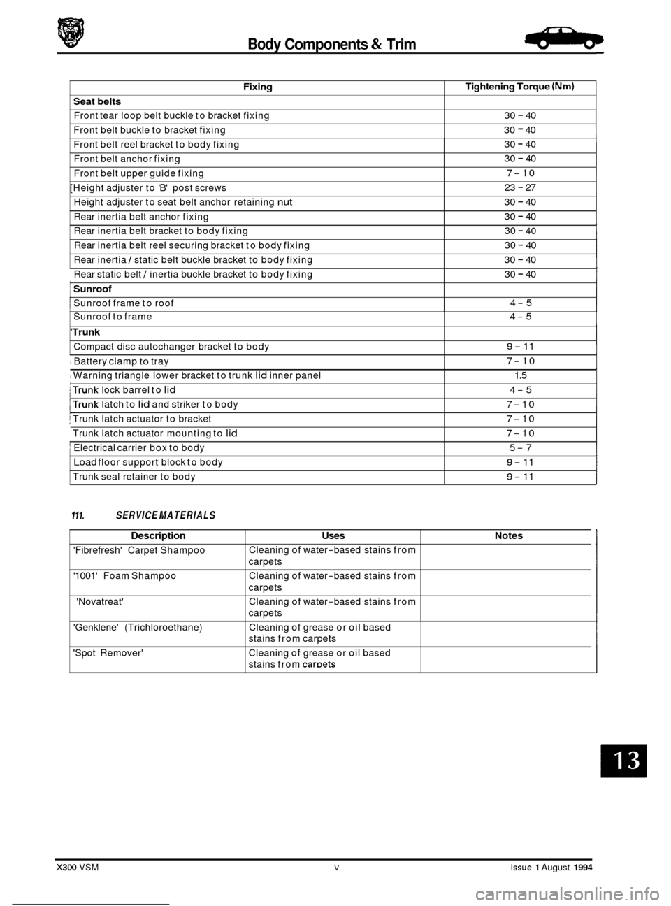
Fixing
Seat belts
Front tear loop belt buckle to bracket fixing
Front belt buckle to bracket fixing
Tightening Torque (Nm)
30 - 40
30
- 40
Front belt reel bracket to body fixing
Front belt anchor fixing 30 - 40
30 - 40
7
-10
23
- 27
30
- 40
30 - 40
30
- 40
30 - 40
30
- 40
Front belt upper guide fixing
[Height adjuster to 'B' post screws
Height adjuster to seat belt anchor retaining
nut
Rear inertia belt anchor fixing
Rear inertia belt bracket to body fixing
Rear inertia belt reel securing bracket to body fixing
Rear inertia
/ static belt buckle bracket to body fixing ~
Rear
static belt / inertia buckle bracket to body fixing
: Sunroof ~
Sunroof frame
to roof
30 - 40
4
-5
111. SERVICE MATERIALS
Sunroof to frame 4-5
'Trunk
Compact disc autochanger bracket to body
I Battery clamp to tray
I Warning triangle lower bracket to trunk lid inner panel
9- 11
7
-10
1.5
X300 VSM V Issue 1 August 1994
I trunk lock barrel to lid
j Trunk latch actuator to bracket
Trunk latch actuator mounting to
lid
j Electrical carrier box to body
Load floor support block to body
Trunk seal retainer to body
trunk latch to lid and striker to body
4-5
7
-10
7
-10
7
-10
5
-7
9- 11
9- 11
Description Uses
'Fibrefresh' Carpet Shampoo
'1001' Foam Shampoo
'Novatreat' Cleaning
of water
-based stains from
carpets
Cleaning of water
-based stains from
carpets
Cleaning of water
-based stains from
carpets
Notes
'Genklene' (Trichloroethane)
'Spot Remover' Cleaning
of grease or oil based
stains from carpets
Cleaning of grease or oil based
stains from
caroets
Page 256 of 521
Body Components & Trim
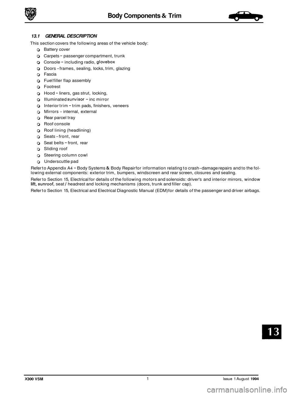
13.1 GENERAL DESCRIPTION
This section covers the following areas of the vehicle body:
0 Battery cover
0 Carpets - passenger compartment, trunk
0 Console - including radio, glovebox
0 Doors -frames, sealing, locks, trim, glazing
0 Fascia
0 Fuel filler flap assembly
0 Footrest
0 Hood - liners, gas strut, locking,
0 Illuminated sunvisor - inc mirror
0 Interior trim - trim pads, finishers, veneers
0 Mirrors - internal, external
0 Rear parcel tray
0 Roof console
0 Roof lining (headlining)
o Seats -front, rear -
0 Seat belts - front, rear
0 Sliding roof
0 Steering column cowl
0 Underscuttle pad
Refer to Appendix
A4 - Body Systems & Body Repair for information relating to crash-damage repairs and to the fol- lowing external components: exterior trim, bumpers, windscreen and rear screen, closures and sealing.
Refer to Section 15, Electrical for details of the following motors and solenoids: driver's and interior mirrors, window
lift, sunroof, seat / headrest and locking mechanisms (doors, trunk and filler cap).
Refer to Section 15, Electrical and Electrical Diagnostic Manual (EDM) for details of the passenger and driver airbags.
X300 VSM 1 Issue 1 August 1994
Page 293 of 521
13.4 TRUNK
13.4.1 Trunk, Description
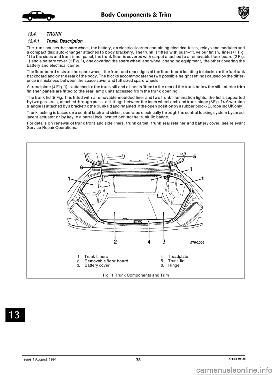
The trunk houses the spare wheel, the battery, an electrical carrier containing electrical fuses, relays and modules and
a compact disc auto-changer attached to body bracketry. The trunk is fitted with push-fit, velour finish, liners (1 Fig. 1) to the sides and front inner panel; the trunk floor is covered with carpet attached to a removable floor board (2 Fig. 1) and a battery cover (3 Fig. I), one covering the spare wheel and wheel changing equipment, the other covering the
battery and electrical carrier.
The floor board rests on the spare wheel, the front and rear edges
of the floor board locating in blocks on the fuel tank
backboard and on the rear of the body. The blocks accommodate the two possible height settings caused by the differ- ence in thickness between the space saver and full sized spare wheels.
A tread plate (4 Fig. 1) is attached to the trunk sill and a liner is fitted to the rear of the trunk below the sill. Interior trim finisher panels are fitted to the rear lamp units accessed from the trunk opening.
The trunk lid
(5 Fig. 1) is fitted with a removable moulded liner and two trunk illumination lights; the lid is supported by two gas struts, attached through press-on fittings between the inner wheel arch and trunk hinge (6 Fig. 1). A warning
triangle is attached by a bracket to the trunk lid and retained in the open position by a rubber block (Europe inc UK only).
Trunk locking is based on a central latch and striker, operated electrically through the central locking system
by an ad- jacent actuator or by key in a barrel lock located behind the trunk lid badge.
For details on renewal
of trunk front and side liners, trunk carpet, trunk seal retainer and battery cover, see relevant
Service Repair Operations.
2 4 3 J76-1056
1. Trunk Liners 2. Removable floor board 3. Battery cover
4. Treadplate 5. Trunk lid 6. Hinge
Fig.
1 Trunk Components and Trim
Issue 1 August 1994 X300 VSM 38
Page 303 of 521
Body Components & Trim a
13.8 SEATING AND SEAT BELTS
13.8.1 Seating, Description
The front seats are available in a range of materials consisting of sculptured fabric / leather, leather, sports cloth / leather, embossed leather / leather and autolux. Both seats are available as 'manual', ie manually adjustable with elec- tric rise and fall, manual height adjustment headrests, 'power', ie 12-way electric adjustment, 'power with memory', ie memory controlled, 12-way electric adjustment of seat, steering column and exterior rear view mirrors and 'heated',
ie with integral heating.
Front seats are based on a non
-handed, one-piece frame which includes cushion and squab frames and seat adjuster
mechanisms. The seat switchpacks (powerseats) are fitted to the outboard side of driver and passenger seats; on 'man- ual'seats, the seat height adjustment switch is similarly located. Seat control modules SCMs are contained within the
seat assemblies. The seats are secured through four mounting points to the vehicle floor.
Rear seats are of the bench type with
full width removable cushion and individual seat squabs.
Electrical components installed on the heel board below the rear passenger seat are protected
by two covers secured
by two locating brackets on the floor and by two latches on the cover. The latches are released by pushing down on
the two recesses in the top edge of the cover.
13.8.2 Front Manual Seat, Renew
. Disconnect vehicle battery ground lead.
. Disconnect electrical connections as required.
. Remove the seat forward fixings.
Move the seat fully forward.
. Remove the rear fixing / slide covers.
. Remove the seat rear fixings.
. Reposition seat for access and remove seat from vehicle.
. To refit seat, carry out reversal of above procedure.
13.8.3
. Disconnect vehicle battery ground lead.
. Move the seat fully forward to gain access to squab back
Remove squab side fixings, disconnect lamp harness and
. To refit, carry out reversal of the above procedure.
Front Seat (Power Operated) Squab Back
Cover, Renew
cover outer fixings.
remove squab back cover.
13.8.4
. Position seat as required for access.
. Disconnect vehicle battery ground lead.
. Release sound insulation retainers and displace insula-
. Remove SCM cover, move SCM aside and remove seat
. Remove the seat forward fixings and move the seat fully
. Remove the seat rearward fixing covers and remove the
. Disconnect multi-plugs, seat switch and motor harness to
. Release harness tie strap and remove seat assembly from
Front Seat (Power Operated), Renew
tion.
switch
multi-plug from its mounting bracket.
forward. seat rearward fixings.
SCM.
vehicle.
. To refit, carry out reversal of the above procedure, ensur- ing that fixings are tightened to the correct torque.
Issue 1 August 1994 48 X300 VSM
0
0
0
Page 306 of 521

Body Components & Trim
13.8.10 Tear loop Seat Belts, Description
The tear loop seat belt (Fig.1) is used to control the rate of forward travel of the occupant towards the deployed airbag
(the airbag is covered in Section 15, Electrical). The tear loop assembly is designed to release additional webbing when
the stitching, which retains the webbing loops, breaks under
a predetermined load. The wires (1 Fig. 1) within the as- sembly have the following functions:
0 To protect the stitching from 'normal' loads such as heavy braking or cornering.
o To control the rate of deployment.
0 To support the extended head following deployment.
When the passenger unit has been activated, the buckle will extend from the shroud and reveal
a warning label (2 Fig. 1); the extent of deployment will depend upon the severity of the load.
-: IF THE LABEL IS VISIBLE AT ALL (3 FIG. 3). THE COMPLETE ASSEMBLY MUST BE RENEWED, AS MUST
ANY SEAT BELT WHICH HAS BEEN WORN IN AN ACCIDENT.
2
Fia. 1 Tear LOOO Seat Belt
X300 VSM 51 Issue 1 August 1994 ~~
Page 318 of 521
Climate Control Systems
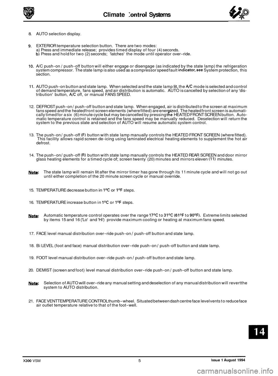
8. AUTO selection display.
9. EXTERIOR temperature selection button. There are two modes:
a) Press and immediate release; provides timed display of four (4) seconds.
b) Press and hold for two (2) seconds; 'latches' the mode until operator over-ride.
10. A/C push-on / push-off button will either engage or disengage (as indicated by the state lamp) the refrigeration
system compressor. The state lamp is also used as a compressor speed fault indicator,see System protection, this
section.
11. AUTO push-on button and state lamp. When selected and the state lamp lit, the A/C mode is selected and control
of demand temperature, fans speed, and air distribution is automatic. AUTO is cancelled by selection of any 'dis- tribution' button, A/C off, or manual FANS SPEED.
12. DEFROST push
-on / push-off button and state lamp. When engaged, air is distributed to the screen at maximum
fans speed and the heated front screen elements (where fitted) are ener ized. The heated front screen is automati- cally timed for a six (6) minute cycle but may be cancelled by pressing tfe HEATED FRONT SCREEN button. Auto- matic temperature control is retained and the fans speed may be manually reduced. Deselection will return the
system to the previous state and selection of AUTO will resume automatic system control.
13. The push
-on / push-off (F) button with state lamp manually controls the HEATED FRONT SCREEN (where fitted).
This facility allows rapid screen de-icing using laminated electrical heating elements to supplement the hot air
defrost.
14. The push-on / push-off (R) button with state lamp manually controls the HEATED REAR SCREEN and door mirror
glass heating elements for a timed cycle of; screen twenty (20) minutes and mirrors eleven (1 1) minutes.
m: The state lamp will remain lit after the mirror timer has gone through its 11 minute cycle and will not go out
until either completion of the 20 minute screen cycle or manual override.
15. TEMPERATURE decrease button
in IoC or I0F steps.
16. TEMPERATURE increase button in
IoC or I0F steps.
w: Automatic temperature control operates over the range 17OC to 31OC (61OF to 90OF). Extreme limits selected
by items 15 and 16 ('Lo' and 'Hi') provide maximum cooling or heating at maximum fans speed.
17. FACE level manual distribution over
-ride push-on / push-off button and state lamp.
0 18. Bi LEVEL (foot and face) manual distribution over-ride push-on / push-off button and state lamp.
19. FOOT level manual distribution over
-ride push-on / push-off button and state lamp.
20. DEMIST (screen and foot) level manual distribution over
-ride push-on / push-off button and state lamp.
!Y&Q: Selection of AUTO will over-ride any manual setting and deselection of any manual distribution will revertthe
system to AUTO distribution.
21. FACE VENTTEMPERATURE CONTROL thumb
-wheel. Situated between dash centre face level vents to reduce face
air outlet temperature relative to that of the foot-well.
Issue 1 August 1994 X300 VSM 5
Page 319 of 521
Climate Control Systems
14.4 TEMPERATURE CONTROL
14.4.1 Coolant Circuit
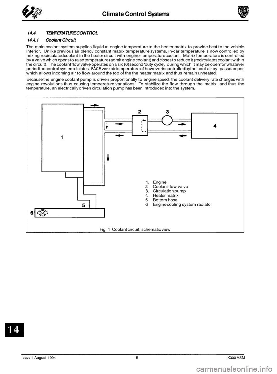
The main coolant system supplies liquid at engine temperature to the heater matrix to provide heat to the vehicle
interior. Unlike previous air blend / constant matrix temperature systems, in-car temperature is now controlled by
mixing recirculated coolant in the heater circuit with engine-temperature coolant. Matrix temperature is controlled
by a valve which opens to raise temperature (admit engine coolant) and closes to reduce it (recirculates coolant within
the circuit). The coolant flow valve operates on a six (6) second 'duty cycle', during which it may be open for whatever
period thecontrol system dictates. FACEvent airtemperature of howeveriscontrolled bythe'cool air by-passdamper'
which allows incoming air to flow around the top of the the heater matrix and thus remain unheated.
Because the engine coolant pump is driven proportionally to engine speed, the coolant delivery rate changes with
engine revolutions thus causing temperature variations. To stabilize the flow through the matrix, and thus the
temperature, an electrically driven circulation pump has been introduced into the system.
1
1. Engine 2. Coolant flow valve 3. Circulation pump
4. Heater matrix
5. Bottom hose
6. Engine cooling system radiator
Fig.
1 Coolant circuit, schematic view
Issue 1 August 1994 6 X300 VSM
Page 322 of 521
Climate Control Systems
CONTROL MODULE FAULT & CONDITION SELF-ANALYSIS
0 14.6 14.6.1 System Health
The climate control system has a 'self-test' facility, accessible from the control panel. The self test sequence has two
basic modes:
0 System error information is stored in the A/CCM up to a maximum of five faults. Should a fault occur there will
be an audible 'beep' and the message 'Er' will be displayed on the control panel LCD for approximately five (5)
seconds after ignition on. Please note that this will happen only once in any ignition switch cycle. The error
source may be accessed by the procedure described in 'Self Test System Diagnosis', this section.
0 Panel communication check may be initiated by following the instruction in 'Self Test System Diagnosis', this
section.
Nsfe: Displayed error codes are NOT directly related to Jaguar Diagnostic Equipment (JDE) but more detailed fault
related information may be accessed using Portable Diagnostic Unit (PDU).
14.6.2 System Protection
Power to the compressor clutch may be cut should either the engine management or air conditioning control systems
detect certain conditions; these conditions may be caused by Fault or Demand and can be classified thus:
0 Engine coolant overheat,
0 Refrigerant excessive pressure.
0 Refrigerant, insufficient pressure or low charge weight.
0 Speed differential between compressor and crankshaft caused by belt slippage or compressor seizure (indi-
cated by A/C state lamp flashing once per second) - 12 cylinder engine only. This feature, 'lock sensing' is fully
explained
in the EDM.
Demand
0 Engine maximum power requirement
0 Electrical system drain at engine idle.
X300 VSM 9 Issue 1 August 1994
Page 323 of 521

Climate Control Systems
14.7 AIR DlSTRlBUTlON
(Refer to illustrations on this and next page)
Air is drawn from the plenum chamber into the heater/cooler case at the lower front right and left hand sides. All air must first pass through the evaporator (not fitted to heater only cars) and then through the heater matrix for in-car distribution.
When cooler air than that available from the other outlets is desired at the FACE vents, air by
-passes the matrix via
the 'cool air by-pass damper' within the range cold to hot.
The flaps for FOOT, COOL AIR, CENTRE VENT, RH & LH RECIRCULATION and DEFROST are electrically driven by indi- vidual motor / potentiometer units.
1. Face outlet
2. Defrost outlet
3. End-of-dash outlet 4. Cool air by-pass damper
5. Evaporator
6. Air in 7. Foot outlet (front)
8. Foot outlet (rear)
9. Rear face outlet 10. Heater matrix
J82-49L
Fig. 1
\d J82-495 \d J82-L96
(Solid arrow = Hot, Line arrow = Cold)
Fig. 2
0
0
0
0
Issue 1 August 1994 10 X300 VSM
Page 325 of 521
Climate Control Systems
14.8 REFRIGERATION CYCLE:
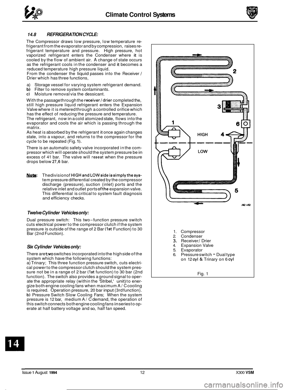
The Compressor draws low pressure, low temperature re- frigerant from the evaporator and by compression, raises re- frigerant temperature and pressure. High pressure, hot
vaporized refrigerant enters the Condenser where it is
cooled by the flow of ambient air.
A change of state occurs
as the refrigerant cools in the condenser and it becomes a
reduced temperature high pressure liquid.
From the condenser the
liquid passes into the Receiver / Drier which has three functions,
a) Storage vessel for varying system refrigerant demand.
b) Filter to remove system contaminants. c) Moisture removal via the dessicant.
With the passage through the
receiver/drier completed the,
still high pressure liquid refrigerant enters the Expansion
Valve where it is metered through a controlled orifice which
has the effect of reducing the pressure and temperature.
The refrigerant, now
in a cold atomized state, flows into the
evaporator and cools the air which is passing through the
matrix.
As heat is absorbed by the refrigerant
it once again changes
state, into a vapour, and returns to the compressor for the
cycle to be repeated (Fig.
1).
There is an automatic safety valve incorporated in the com- pressor which will operate should the system pressure be in
excess of 41 bar. The valve will reseat when the pressure
drops below 27,6 bar.
W Thedivisionof HIGHandLOWsideissimplythesys- tem pressure differential created by the compressor
discharge (pressure), suction (inlet) ports and the
relative inlet and outlet ports
ofthe expansion valve.
This differential is critical to system fault diagnosis
and efficiency checks.
Twelve Cylinder Vehicles only:
Dual pressure switch: This two-function pressure switch
cuts electrical power to the compressor clutch if the system
pressure is outside of the range
of 2 Bar (1st Function) to 30
Bar (2nd Function).
Six Cylinder Vehicles only:
There are two switches incorporated into the high side of the
system which have the following functions:
a) Trinary; This three function pressure switch, cuts electri
-
cal power to the compressor clutch should the system pres- sure not be in a range of 2 bar (1st function) to 30 bar (2nd
function). The switch also provides a ground signal to oper
- ate the appropriate relay (within the 'Stribel,' unit) to ener- gize both engine cooling fans when maximum A/ C cooling
is required. Operation pressure, 20 bar input (3rd function).
b) Pressure Switch Slow Cooling Fans; When the system
pressure is 12 bar, medium A/ C demand, the operation of
this switch connects both engine cooling fans in series to op- erate at half battery voltage and so, half fan speed. 1.
Compressor
2. Condenser
3. Receiver / Drier 4. Expansion Valve
5. Evaporator
6. Pressure switch - Dual type
on 12
cyl & Trinary on 6 cyl
Fig. 1
0
0
Issue 1 August 1994 12 X300 VSM