JEEP CHEROKEE 1995 Service Repair Manual
Manufacturer: JEEP, Model Year: 1995, Model line: CHEROKEE, Model: JEEP CHEROKEE 1995Pages: 2198, PDF Size: 82.83 MB
Page 1871 of 2198
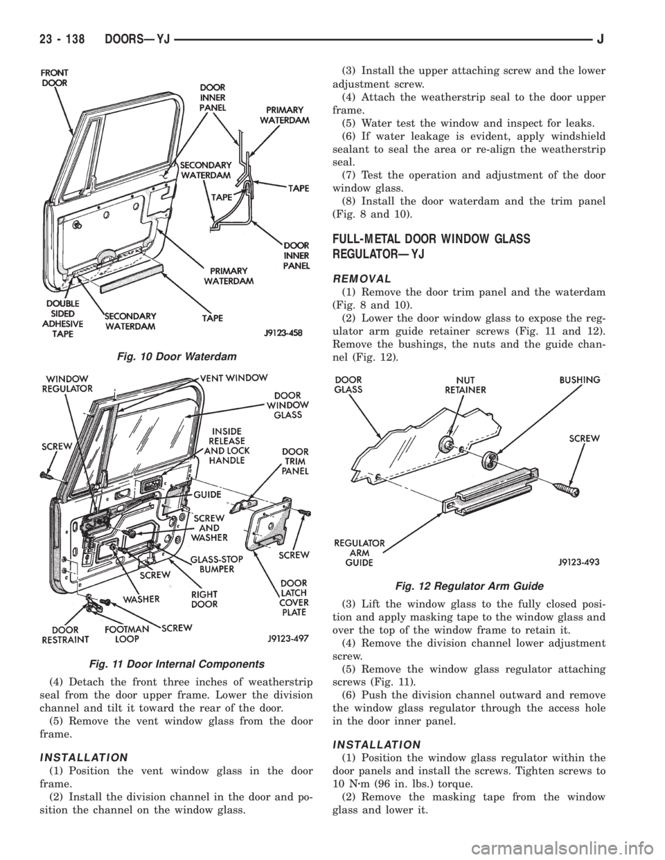
(4) Detach the front three inches of weatherstrip
seal from the door upper frame. Lower the division
channel and tilt it toward the rear of the door.
(5) Remove the vent window glass from the door
frame.
INSTALLATION
(1) Position the vent window glass in the door
frame.
(2) Install the division channel in the door and po-
sition the channel on the window glass.(3) Install the upper attaching screw and the lower
adjustment screw.
(4) Attach the weatherstrip seal to the door upper
frame.
(5) Water test the window and inspect for leaks.
(6) If water leakage is evident, apply windshield
sealant to seal the area or re-align the weatherstrip
seal.
(7) Test the operation and adjustment of the door
window glass.
(8) Install the door waterdam and the trim panel
(Fig. 8 and 10).
FULL-METAL DOOR WINDOW GLASS
REGULATORÐYJ
REMOVAL
(1) Remove the door trim panel and the waterdam
(Fig. 8 and 10).
(2) Lower the door window glass to expose the reg-
ulator arm guide retainer screws (Fig. 11 and 12).
Remove the bushings, the nuts and the guide chan-
nel (Fig. 12).
(3) Lift the window glass to the fully closed posi-
tion and apply masking tape to the window glass and
over the top of the window frame to retain it.
(4) Remove the division channel lower adjustment
screw.
(5) Remove the window glass regulator attaching
screws (Fig. 11).
(6) Push the division channel outward and remove
the window glass regulator through the access hole
in the door inner panel.
INSTALLATION
(1) Position the window glass regulator within the
door panels and install the screws. Tighten screws to
10 Nzm (96 in. lbs.) torque.
(2) Remove the masking tape from the window
glass and lower it.
Fig. 10 Door Waterdam
Fig. 11 Door Internal Components
Fig. 12 Regulator Arm Guide
23 - 138 DOORSÐYJJ
Page 1872 of 2198
(3) Slide the regulator arm guide onto the regula-
tor arm and position the guide on the window glass
(Fig. 12). Install the nuts, bushings and screws.
(4) Install the division channel lower adjustment
screw.
(5) Test the window glass for proper operation.
(6) Install the door waterdam and the trim panel
(Fig. 8 and 10).
FULL-METAL DOOR WINDOW GLASSÐYJ
ADJUSTMENT
One adjustment location provides amount of effort
required to raise and lower the door window glass.
The door window glass division channel is adjustable
fore and aft at the lower attaching location.
(1) Remove the door trim panel and the waterdam
(Fig. 8 and 10).
(2) Loosen channel lower adjustment screw and
move the division channel fore or aft to obtain the
desired door window glass operation.
Movement of the division channel fore or aft
will decrease or increase the free-play between
the channels.
(3) Tighten the division channel lower adjustment
screw.
(4) Install the door waterdam and the trim panel
(Fig. 8 and 10).
REMOVAL
(1) Remove the door trim panel and the waterdam
(Fig. 8 and 10).
(2) Remove the window glass down-stop bumper
(Fig. 11).
(3) Remove the screws that attach the regulator
arm guide to the window glass. Remove the screws,
bushings, nuts and the guide from the glass (Fig. 11).
(4) Lower the window glass to the bottom of the
door.
(5) Remove the division channel upper attaching
screw and the lower adjustment screw. Detach the
front 3 inches of window glass weatherstrip seal from
the door upper frame.
(6) Separate the division channel from the front
window glass rubber seal. Pull the division channel
up and in toward the inside of vehicle.
(7) Raise and tilt the window glass toward the
hinge side of the door and disengage it from the rear
channel.
(8) Pull the window glass up and out of the door
panel.
INSTALLATION
(1) Lower the window glass into the door, while in-
serting the window glass into the front and rear
channels.
(2) Slide the window glass downward to the bottom
of the door panel.(3) Lower the division channel into the door and
position the window glass securely in the channel.
(4) Install the weatherstrip seal in the upper door
frame and install the upper attaching screw and the
lower adjustment screw.
(5) Slide the guide onto the regulator arm and po-
sition the guide on the window glass. Install the re-
taining nuts, bushings and screws (Fig. 12).
(6) Install the window glass down-stop bumper
(Fig. 11).
(7) Test the window operation for proper adjust-
ment.
(8) Install the door waterdam and the trim panel
(Fig. 8 and 10).
FULL-METAL DOOR KEY LOCK CYLINDERÐYJ
REMOVAL
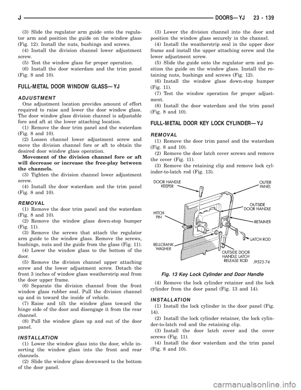
(1) Remove the door trim panel and the waterdam
(Fig. 8 and 10).
(2) Remove the door latch cover screws and remove
the cover (Fig. 11).
(3) Remove the retaining clip and remove lock cyl-
inder-to-latch rod (Fig. 13).
(4) Remove the lock cylinder retainer and the lock
cylinder from the door panel (Fig. 13 and 14).
INSTALLATION
(1) Install the lock cylinder in the door panel (Fig.
14).
(2) Install the lock cylinder retainer, the lock cylin-
der-to-latch rod and the retaining clip.
(3) Install the door latch cover and the cover
screws (Fig. 11).
(4) Install the door waterdam and the trim panel
(Fig. 8 and 10).
Fig. 13 Key Lock Cylinder and Door Handle
JDOORSÐYJ 23 - 139
Page 1873 of 2198
FULL-METAL DOOR LATCH EXTERNAL RELEASE
HANDLEÐYJ
REMOVAL
(1) Remove the door trim panel and the waterdam
from the door inner panel (Fig. 8 and 10).
(2) Remove the door latch cover attaching screws
(Fig. 11).
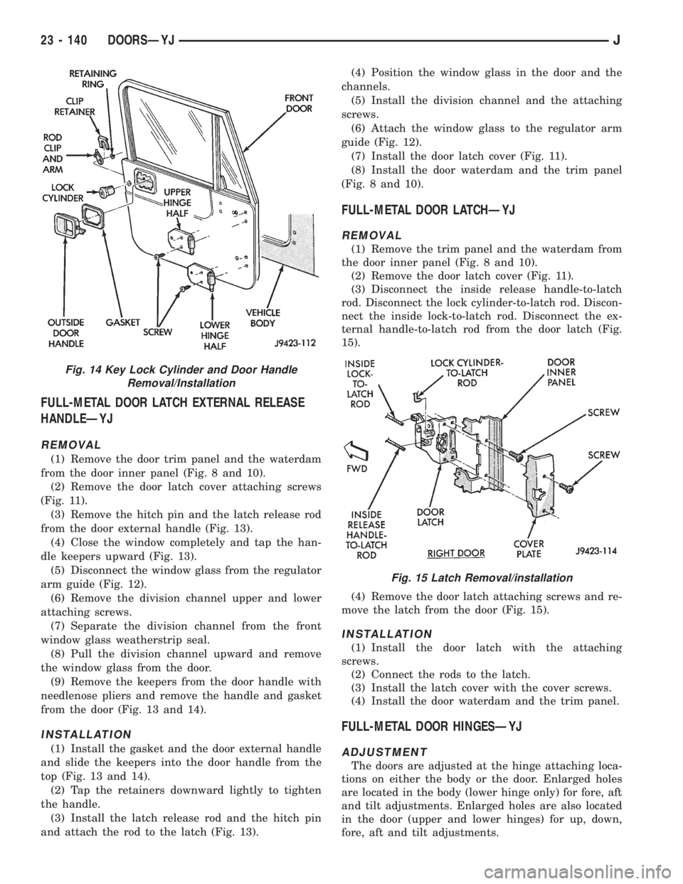
(3) Remove the hitch pin and the latch release rod
from the door external handle (Fig. 13).
(4) Close the window completely and tap the han-
dle keepers upward (Fig. 13).
(5) Disconnect the window glass from the regulator
arm guide (Fig. 12).
(6) Remove the division channel upper and lower
attaching screws.
(7) Separate the division channel from the front
window glass weatherstrip seal.
(8) Pull the division channel upward and remove
the window glass from the door.
(9) Remove the keepers from the door handle with
needlenose pliers and remove the handle and gasket
from the door (Fig. 13 and 14).
INSTALLATION
(1) Install the gasket and the door external handle
and slide the keepers into the door handle from the
top (Fig. 13 and 14).
(2) Tap the retainers downward lightly to tighten
the handle.
(3) Install the latch release rod and the hitch pin
and attach the rod to the latch (Fig. 13).(4) Position the window glass in the door and the
channels.
(5) Install the division channel and the attaching
screws.
(6) Attach the window glass to the regulator arm
guide (Fig. 12).
(7) Install the door latch cover (Fig. 11).
(8) Install the door waterdam and the trim panel
(Fig. 8 and 10).
FULL-METAL DOOR LATCHÐYJ
REMOVAL
(1) Remove the trim panel and the waterdam from
the door inner panel (Fig. 8 and 10).
(2) Remove the door latch cover (Fig. 11).
(3) Disconnect the inside release handle-to-latch
rod. Disconnect the lock cylinder-to-latch rod. Discon-
nect the inside lock-to-latch rod. Disconnect the ex-
ternal handle-to-latch rod from the door latch (Fig.
15).
(4) Remove the door latch attaching screws and re-
move the latch from the door (Fig. 15).
INSTALLATION
(1) Install the door latch with the attaching
screws.
(2) Connect the rods to the latch.
(3) Install the latch cover with the cover screws.
(4) Install the door waterdam and the trim panel.
FULL-METAL DOOR HINGESÐYJ
ADJUSTMENT
The doors are adjusted at the hinge attaching loca-
tions on either the body or the door. Enlarged holes
are located in the body (lower hinge only) for fore, aft
and tilt adjustments. Enlarged holes are also located
in the door (upper and lower hinges) for up, down,
fore, aft and tilt adjustments.
Fig. 14 Key Lock Cylinder and Door Handle
Removal/Installation
Fig. 15 Latch Removal/installation
23 - 140 DOORSÐYJJ
Page 1874 of 2198
Prior to door adjustment or alignment, the door
latch must be removed to allow the door to close
freely and be properly aligned.
The door latch striker should be adjusted in or out
to allow the door latch to be fully engaged. The door
should be flush with the adjacent body panels.
REPLACEMENT
(1) Mark the outline of the existing hinge on the
body and the door with a wax pencil for installation
alignment reference.
When removing the door or hinge DO NOT
discard the plastic shims or the hinge pin.
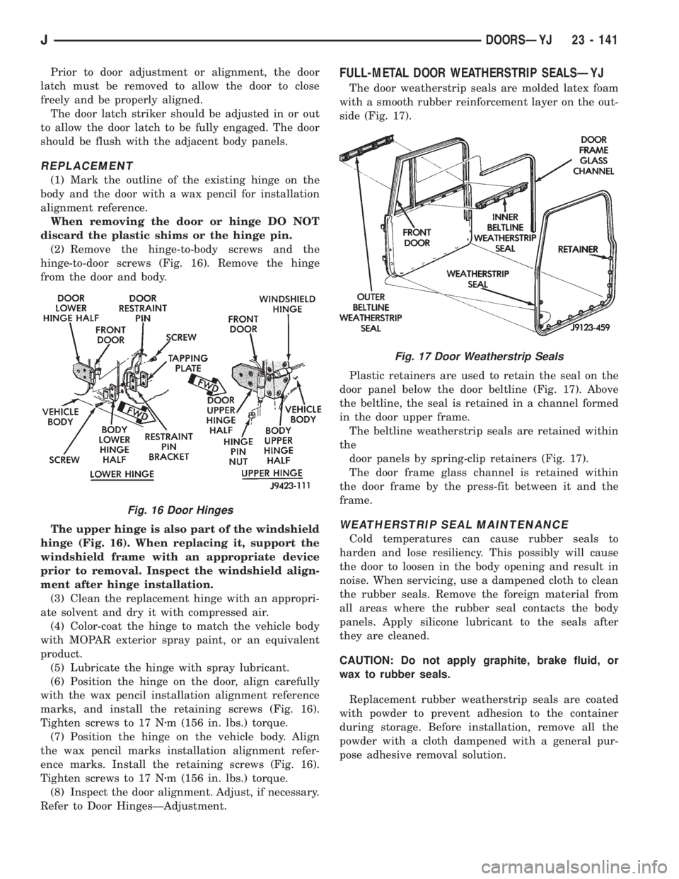
(2) Remove the hinge-to-body screws and the
hinge-to-door screws (Fig. 16). Remove the hinge
from the door and body.
The upper hinge is also part of the windshield
hinge (Fig. 16). When replacing it, support the
windshield frame with an appropriate device
prior to removal. Inspect the windshield align-
ment after hinge installation.
(3) Clean the replacement hinge with an appropri-
ate solvent and dry it with compressed air.
(4) Color-coat the hinge to match the vehicle body
with MOPAR exterior spray paint, or an equivalent
product.
(5) Lubricate the hinge with spray lubricant.
(6) Position the hinge on the door, align carefully
with the wax pencil installation alignment reference
marks, and install the retaining screws (Fig. 16).
Tighten screws to 17 Nzm (156 in. lbs.) torque.
(7) Position the hinge on the vehicle body. Align
the wax pencil marks installation alignment refer-
ence marks. Install the retaining screws (Fig. 16).
Tighten screws to 17 Nzm (156 in. lbs.) torque.
(8) Inspect the door alignment. Adjust, if necessary.
Refer to Door HingesÐAdjustment.
FULL-METAL DOOR WEATHERSTRIP SEALSÐYJ
The door weatherstrip seals are molded latex foam
with a smooth rubber reinforcement layer on the out-
side (Fig. 17).
Plastic retainers are used to retain the seal on the
door panel below the door beltline (Fig. 17). Above
the beltline, the seal is retained in a channel formed
in the door upper frame.
The beltline weatherstrip seals are retained within
the
door panels by spring-clip retainers (Fig. 17).
The door frame glass channel is retained within
the door frame by the press-fit between it and the
frame.
WEATHERSTRIP SEAL MAINTENANCE
Cold temperatures can cause rubber seals to
harden and lose resiliency. This possibly will cause
the door to loosen in the body opening and result in
noise. When servicing, use a dampened cloth to clean
the rubber seals. Remove the foreign material from
all areas where the rubber seal contacts the body
panels. Apply silicone lubricant to the seals after
they are cleaned.
CAUTION: Do not apply graphite, brake fluid, or
wax to rubber seals.
Replacement rubber weatherstrip seals are coated
with powder to prevent adhesion to the container
during storage. Before installation, remove all the
powder with a cloth dampened with a general pur-
pose adhesive removal solution.
Fig. 16 Door Hinges
Fig. 17 Door Weatherstrip Seals
JDOORSÐYJ 23 - 141
Page 1875 of 2198
DOOR WEATHERSTRIP SEAL REPLACEMENTÐYJ
REMOVAL
(1) Carefully remove the weatherstrip seal from
the door with a weatherstrip seal removal tool. Pry
the seal outward to separate the plastic retainers
from the door panel holes.
(2) Remove the upper portion of the seal from the
door upper frame with your fingers or a wooden
wand.
(3) Remove the dust and residual adhesive from
the door panel and body panel.
INSTALLATION
(1) Apply adhesive to the front, rear and bottom
edges of the door from the beltline downward.
(2) Install the upper front corner of the seal on the
door first using your fingers or a wooden wand to po-
sition the seal in the channel. Place the inner shoul-
der of the seal in the channel-to-window frame above
the beltline.
(3) Force the retainers, starting at the rear edge of
the door, into the door panel holes.
(4) Ensure that the seal is completely seated
around the door.
BELTLINE SEALÐYJ
REMOVAL
(1) Carefully remove the beltline weatherstrip seal
(Fig. 17) from the door with a weatherstrip seal re-
moval tool or similar pry tool.
(2) Pry the seal upward to remove it from within
the glass and door panel.
INSTALLATION
(1) Position the seal between the door panel and
the glass. Force the seal downward with your fingers
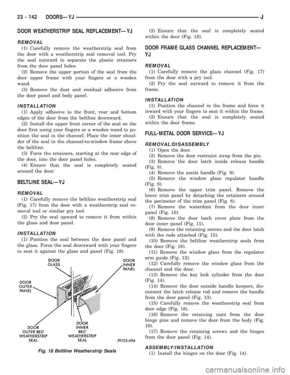
to seat it against the glass and panel (Fig. 18).(2) Ensure that the seal is completely seated
within the door (Fig. 18).
DOOR FRAME GLASS CHANNEL REPLACEMENTÐ
YJ
REMOVAL
(1) Carefully remove the glass channel (Fig. 17)
from the door with a pry tool.
(2) Pry the seal outward to remove it from the
frame.
INSTALLATION
(1) Position the channel in the frame and force it
inward with your fingers to seat it within the frame.
(2) Ensure that the seal is completely seated
within the door frame.
FULL-METAL DOOR SERVICEÐYJ
REMOVAL/DISASSEMBLY
(1) Open the door.
(2) Remove the door restraint strap from the pin.
(3) Remove the door latch inside release handle
(Fig. 8).
(4) Remove the assist handle (Fig. 8).
(5) Remove the window glass regulator handle
(Fig. 8).
(6) Remove the upper trim panel. Remove the
lower trim panel by detaching the retainers around
the perimeter of the trim panel (Fig. 8).
(7) Remove the waterdam from the door inner
panel (Fig. 10).
(8) Remove the door latch cover plate from the
door inner panel (Fig. 11).
(9) Remove the retaining screws and the door latch
with the rods attached (Fig. 15).
(10) Remove the beltline weatherstrip seals from
the door (Fig. 18).
(11) Remove the window glass from the regulator
arm guide (Fig. 12).
(12) Carefully remove the window glass from the
channel and the door.
(13) Remove the key lock cylinder from the door
(Fig. 14).
(14) Remove the door outside handle keepers, dis-
connect the latch release rod and remove the handle
from the door panel (Fig. 13).
(15) Carefully remove the weatherstrip seal from
door edge (Fig. 18).
(16) Remove the retaining nuts from the door
hinge pins and remove the door from the body (Fig.
16).
(17) Remove the retaining screws and the hinges
from the door panel (Fig. 14).
ASSEMBLY/INSTALLATION
(1) Install the hinges on the door (Fig. 14).Fig. 18 Beltline Weatherstrip Seals
23 - 142 DOORSÐYJJ
Page 1876 of 2198
(2) Position the door at the body opening, insert
the hinge pins in the hinge receptacles and install
the retaining nuts (Fig. 16). Tighten the nuts se-
curely.
(3) Install the weatherstrip seal on the door edge
(Fig. 18).
(4) Install the door outside handle and the keepers.
Connect the latch release rod to the handle (Fig. 13).
(5) Install the key lock cylinder (Fig. 14).
(6) Position the window glass in the channel and
the door.
(7) Attach the window glass to the regulator arm
guide (Fig. 12).
(8) Install the beltline weatherstrip seals in the
door (Fig. 18).
(9) Position the latch in the door and install the re-
taining screws (Fig. 15). Tighten the screws securely.
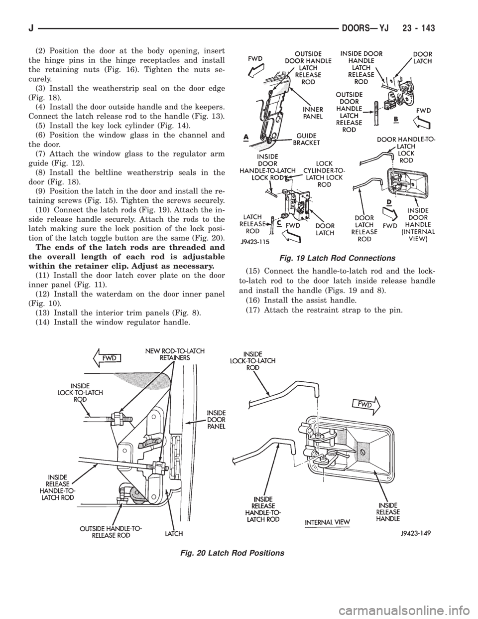
(10) Connect the latch rods (Fig. 19). Attach the in-
side release handle securely. Attach the rods to the
latch making sure the lock position of the lock posi-
tion of the latch toggle button are the same (Fig. 20).
The ends of the latch rods are threaded and
the overall length of each rod is adjustable
within the retainer clip. Adjust as necessary.
(11) Install the door latch cover plate on the door
inner panel (Fig. 11).
(12) Install the waterdam on the door inner panel
(Fig. 10).
(13) Install the interior trim panels (Fig. 8).
(14) Install the window regulator handle.(15) Connect the handle-to-latch rod and the lock-
to-latch rod to the door latch inside release handle
and install the handle (Figs. 19 and 8).
(16) Install the assist handle.
(17) Attach the restraint strap to the pin.
Fig. 19 Latch Rod Connections
Fig. 20 Latch Rod Positions
JDOORSÐYJ 23 - 143
Page 1877 of 2198
STATIONARY GLASS
INDEX
page page
Hard Top Quarter Window GlassÐYJ......... 149
Rearview Mirror Retaining BracketÐYJ........ 144
Rearview MirrorÐYJ...................... 144
Stationary Glass Water Leak Detection and
RepairÐYJ........................... 150Windshield Frame Weatherstrip SealÐYJ...... 146
Windshield FrameÐYJ.................... 145
Windshield GlassÐYJ..................... 146
Windshield Reveal MoldingÐYJ............. 144
WINDSHIELD REVEAL MOLDINGÐYJ
REMOVAL
(1) Disengage the reveal molding around the pe-
rimeter of the windshield glass with an appropriate
tool.
(2) Remove the moldings from the windshield
frame.
(3) Inspect the reveal molding retainers. Replace
the molding if it has broken, distorted or ineffective
retainers.
INSTALLATION
(1) Position the reveal moldings on the windshield
frame.
(2) Attach the moldings to the frame by tapping
each molding with a rubber mallet to seat the retain-
ers.
REARVIEW MIRRORÐYJ
REMOVAL/INSTALLATION
(1) Loosen the mirror set screw and slide the mir-
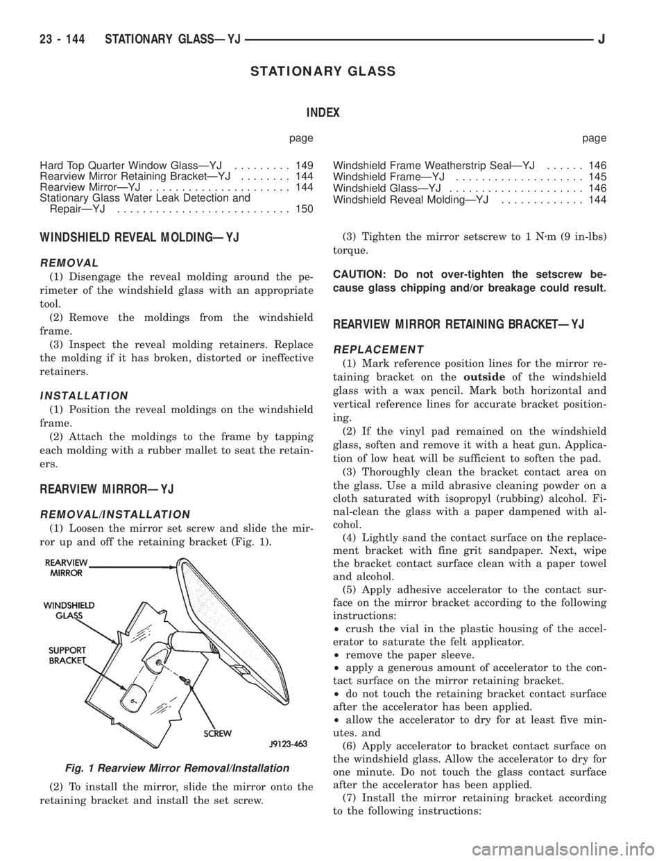
ror up and off the retaining bracket (Fig. 1).
(2) To install the mirror, slide the mirror onto the
retaining bracket and install the set screw.(3) Tighten the mirror setscrew to 1 Nzm (9 in-lbs)
torque.
CAUTION: Do not over-tighten the setscrew be-
cause glass chipping and/or breakage could result.
REARVIEW MIRROR RETAINING BRACKETÐYJ
REPLACEMENT
(1) Mark reference position lines for the mirror re-
taining bracket on theoutsideof the windshield
glass with a wax pencil. Mark both horizontal and
vertical reference lines for accurate bracket position-
ing.
(2) If the vinyl pad remained on the windshield
glass, soften and remove it with a heat gun. Applica-
tion of low heat will be sufficient to soften the pad.
(3) Thoroughly clean the bracket contact area on
the glass. Use a mild abrasive cleaning powder on a
cloth saturated with isopropyl (rubbing) alcohol. Fi-
nal-clean the glass with a paper dampened with al-
cohol.
(4) Lightly sand the contact surface on the replace-
ment bracket with fine grit sandpaper. Next, wipe
the bracket contact surface clean with a paper towel
and alcohol.
(5) Apply adhesive accelerator to the contact sur-
face on the mirror bracket according to the following
instructions:
²crush the vial in the plastic housing of the accel-
erator to saturate the felt applicator.
²remove the paper sleeve.
²apply a generous amount of accelerator to the con-
tact surface on the mirror retaining bracket.
²do not touch the retaining bracket contact surface
after the accelerator has been applied.
²allow the accelerator to dry for at least five min-
utes. and
(6) Apply accelerator to bracket contact surface on
the windshield glass. Allow the accelerator to dry for
one minute. Do not touch the glass contact surface
after the accelerator has been applied.
(7) Install the mirror retaining bracket according
to the following instructions:
Fig. 1 Rearview Mirror Removal/Installation
23 - 144 STATIONARY GLASSÐYJJ
Page 1878 of 2198
²Apply one drop of adhesive at the center of the re-
taining bracket contact surface on the windshield
glass.
²Immediately apply an even coat of adhesive to the
contact surface on the retaining bracket.
²Align the retaining bracket with the position refer-
ence lines on the windshield glass.
²Press and hold the retaining bracket in-place for
at least one minute.
Ensure that the mirror retaining bracket is
correctly aligned because the adhesive will
cure rapidly.
(8) Allow the adhesive to cure for 8-10 minutes,
then remove any residue adhesive with an alcohol
dampened cloth.
(9) Allow the adhesive to cure for an additional
8-10 minutes before installing the mirror on the re-
taining bracket (Fig. 1).
WINDSHIELD FRAMEÐYJ
SERVICE INFORMATION
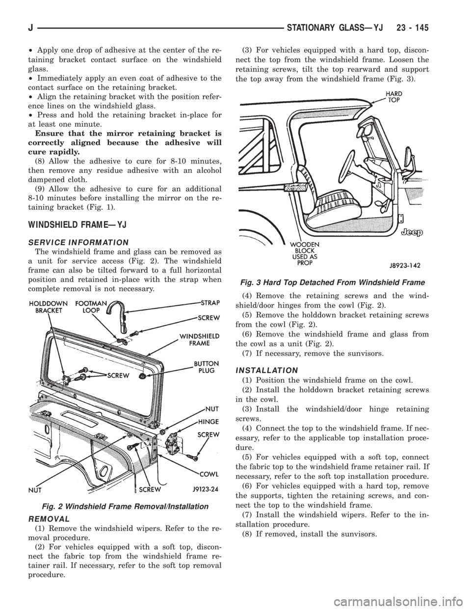
The windshield frame and glass can be removed as
a unit for service access (Fig. 2). The windshield
frame can also be tilted forward to a full horizontal
position and retained in-place with the strap when
complete removal is not necessary.
REMOVAL
(1) Remove the windshield wipers. Refer to the re-
moval procedure.
(2) For vehicles equipped with a soft top, discon-
nect the fabric top from the windshield frame re-
tainer rail. If necessary, refer to the soft top removal
procedure.(3) For vehicles equipped with a hard top, discon-
nect the top from the windshield frame. Loosen the
retaining screws, tilt the top rearward and support
the top away from the windshield frame (Fig. 3).
(4) Remove the retaining screws and the wind-
shield/door hinges from the cowl (Fig. 2).
(5) Remove the holddown bracket retaining screws
from the cowl (Fig. 2).
(6) Remove the windshield frame and glass from
the cowl as a unit (Fig. 2).
(7) If necessary, remove the sunvisors.
INSTALLATION
(1) Position the windshield frame on the cowl.
(2) Install the holddown bracket retaining screws
in the cowl.
(3) Install the windshield/door hinge retaining
screws.
(4) Connect the top to the windshield frame. If nec-
essary, refer to the applicable top installation proce-
dure.
(5) For vehicles equipped with a soft top, connect
the fabric top to the windshield frame retainer rail. If
necessary, refer to the soft top installation procedure.
(6) For vehicles equipped with a hard top, remove
the supports, tighten the retaining screws, and con-
nect the top to the windshield frame.
(7) Install the windshield wipers. Refer to the in-
stallation procedure.
(8) If removed, install the sunvisors.
Fig. 2 Windshield Frame Removal/Installation
Fig. 3 Hard Top Detached From Windshield Frame
JSTATIONARY GLASSÐYJ 23 - 145
Page 1879 of 2198
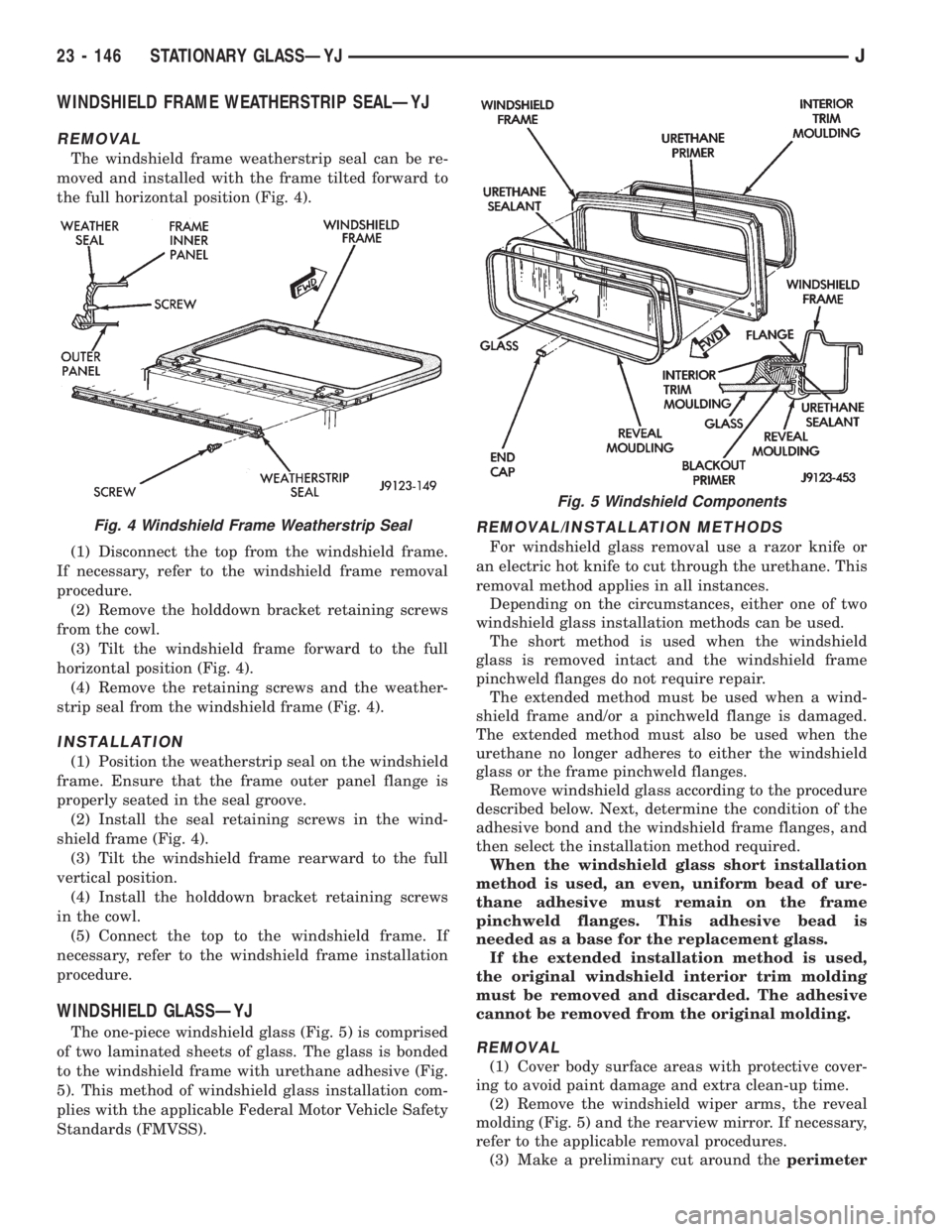
WINDSHIELD FRAME WEATHERSTRIP SEALÐYJ
REMOVAL
The windshield frame weatherstrip seal can be re-
moved and installed with the frame tilted forward to
the full horizontal position (Fig. 4).
(1) Disconnect the top from the windshield frame.
If necessary, refer to the windshield frame removal
procedure.
(2) Remove the holddown bracket retaining screws
from the cowl.
(3) Tilt the windshield frame forward to the full
horizontal position (Fig. 4).
(4) Remove the retaining screws and the weather-
strip seal from the windshield frame (Fig. 4).
INSTALLATION
(1) Position the weatherstrip seal on the windshield
frame. Ensure that the frame outer panel flange is
properly seated in the seal groove.
(2) Install the seal retaining screws in the wind-
shield frame (Fig. 4).
(3) Tilt the windshield frame rearward to the full
vertical position.
(4) Install the holddown bracket retaining screws
in the cowl.
(5) Connect the top to the windshield frame. If
necessary, refer to the windshield frame installation
procedure.
WINDSHIELD GLASSÐYJ
The one-piece windshield glass (Fig. 5) is comprised
of two laminated sheets of glass. The glass is bonded
to the windshield frame with urethane adhesive (Fig.
5). This method of windshield glass installation com-
plies with the applicable Federal Motor Vehicle Safety
Standards (FMVSS).
REMOVAL/INSTALLATION METHODS
For windshield glass removal use a razor knife or
an electric hot knife to cut through the urethane. This
removal method applies in all instances.
Depending on the circumstances, either one of two
windshield glass installation methods can be used.
The short method is used when the windshield
glass is removed intact and the windshield frame
pinchweld flanges do not require repair.
The extended method must be used when a wind-
shield frame and/or a pinchweld flange is damaged.
The extended method must also be used when the
urethane no longer adheres to either the windshield
glass or the frame pinchweld flanges.
Remove windshield glass according to the procedure
described below. Next, determine the condition of the
adhesive bond and the windshield frame flanges, and
then select the installation method required.
When the windshield glass short installation
method is used, an even, uniform bead of ure-
thane adhesive must remain on the frame
pinchweld flanges. This adhesive bead is
needed as a base for the replacement glass.
If the extended installation method is used,
the original windshield interior trim molding
must be removed and discarded. The adhesive
cannot be removed from the original molding.
REMOVAL
(1) Cover body surface areas with protective cover-
ing to avoid paint damage and extra clean-up time.
(2) Remove the windshield wiper arms, the reveal
molding (Fig. 5) and the rearview mirror. If necessary,
refer to the applicable removal procedures.
(3) Make a preliminary cut around theperimeter
Fig. 4 Windshield Frame Weatherstrip Seal
Fig. 5 Windshield Components
23 - 146 STATIONARY GLASSÐYJJ
Page 1880 of 2198
of the windshield glass along the glass edge with a
razor knife.
CAUTION: When cutting through the urethane with
a hot knife blade, do not allow the knife blade to re-
main stationary at any location.
(4) Cut the adhesive bead with a hot knife and a
straight or hooked knife blade.
(5) Start the hot knife blade between the glass and
the urethane. Next, cut the adhesive as close to the
glass edge as possible. Allow as much adhesive to re-
main on the frame flange as possible.For best cut-
ting results, clean the knife blade frequently
with steel wool while the blade is hot.
(6) Remove the windshield glass from the frame
(Fig. 5).
(7) After the hot knife blade has cooled, clean the
hot knife blade with solvent and a cloth. Sharpen the
blade with a fine-tooth file.
(8) If the extended windshield glass installation
method will be used, remove and discard the interior
trim molding (Fig. 5).
INSTALLATIONÐSHORT METHOD
Normally, after a windshield is installed, the rear-
view mirror bracket also requires installation. If so,
refer to the rearview mirror bracket replacement pro-
cedure.Do not install bracket until after wind-
shield installation is completed.
(1) Inspect the windshield frame pinchweld flanges
(Fig. 5) Prime any bare spots with urethane primer.
Allow a minimum of 18 minutes for dry time.
(2) Inspect the urethane bead for high spots. Level
the bead by shaving off high spots with a razor knife.
This is necessary for a flush-fit of the windshield
glass.
(3) Inspect the windshield molding. Replace the
molding if it has broken, distorted or ineffective re-
tainers.
(4) Clean the outer edge of the windshield glass
with naphtha or a similar product.
(5) Prime the outer perimeter of the interior side of
the glass 16 mm (5/8 inch) from the edge. Use a
wipe-off type urethane primer and wipe the glass dry
after primer application.
(6) Place the windshield glass in the frame on the
pinchweld flanges and inspect for gaps in the ure-
thane adhesive. Gaps in excess of 3 mm (1/8 inch)
must be filled with additional urethane adhesive.
(7) Adjust windshield glass position until it is
aligned with the flanges and the adhesive. Next,
make alignment marks on glass and body with a
grease pencil.
(8) Remove the windshield glass and position it on
a flat surface.
(9) If the replacement windshield glass does not
have blackout primer:²Attach a 25-mm (1-in) wide masking tape band
around the interior side of the glass 16 mm (5/8 in)
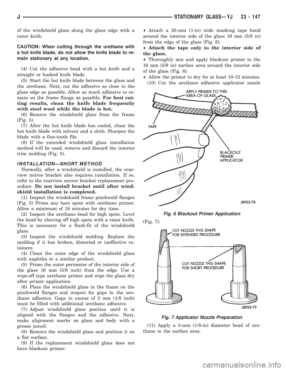
from the edge of the glass (Fig. 6).
²Attach the tape only to the interior side of
the glass.
²Thoroughly mix and apply blackout primer to the
16 mm (5/8 in) surface area around the interior side
of the glass (Fig. 6).
²Allow the primer to dry for at least 10-12 minutes.
(10) Cut the urethane adhesive applicator nozzle
(Fig. 7).
(11) Apply a 3-mm (1/8-in) diameter bead of ure-
thane to the surface area.
Fig. 6 Blackout Primer Application
Fig. 7 Applicator Nozzle Preparation
JSTATIONARY GLASSÐYJ 23 - 147