JEEP CHEROKEE 1995 Service Repair Manual
Manufacturer: JEEP, Model Year: 1995, Model line: CHEROKEE, Model: JEEP CHEROKEE 1995Pages: 2198, PDF Size: 82.83 MB
Page 1911 of 2198
off switch for battery voltage. If no voltage is present
test pressure cut-off switch. If voltage is present go
to next step.
(5) With ohmmeter test harness connector ground
circuit for continuity to ground. If circuit is open, (no
continuity) repair ground circuit. If circuit test OK
and clutch does not engage refer to Powertrain Diag-
nostic Service Manual for A/C clutch circuit test.
AIR CONDITIONING CONTROLSÐYJ VEHICLES
The air conditioning circuit consists of 3 segments;
battery supply, blower motor and compressor clutch.
The 3 segments have a common connection point at
the blower switch.
The power supply circuit extends from the HTR/
FAN fuse to the blower switch. From the blower
switch, battery feed is routed to the blower motor
and compressor clutch circuit.
Refer to Group 8W Wiring Diagrams for wiring
schematic and terminals. Use volt ohmmeter to test
switches.
COMPRESSOR CLUTCH
The clutch assembly consists of a stationary elec-
tromagnetic coil, hub bearing pulley assembly, and
clutch plate. When the coil is energized the plate is
magnetically engaged with the pulley and turns the
compressor shaft.
COMPRESSOR CLUTCH TEST
(1) Unplug clutch coil connector.
(2) Connect jumper wire from battery positive post
to clutch coil connector. The clutch should engage, if
not leave jumper wire connected and go to next step.
(3) Connect jumper wire from clutch coil frame to
chassis ground. The clutch should engage, if not re-
pair clutch coil ground or replace coil.
A/C COMPRESSOR CLUTCH RELAY
The A/C compressor clutch relay controls the 12-
volt source to the A/C clutch. The relay is activated
when the PCM receives a A/C request signal. The
PCM then sends a ground signal to the relay. The re-
lay is activated and sends 12-volts to the clutch coil
which energizes the clutch. The relay is located in
the power distribution center.
COMPRESSOR CLUTCH RELAY TEST
For test procedure refer to Powertrain Diagnostic
Service Manual for A/C clutch relay circuit test.
LOW-PRESSURE HIGH-PRESSURE CUT-OFF
SWITCH
The pressure cut-off switch is located on the filter
drier and is wired in series with compressor clutch.
The switch interrupts the power to the compressorclutch circuit when the pressure drops to 193 kPa (28
psi) or increases above 3100 to 3375 kPa (450 to 490
psi).
PRESSURE CUT-OFF SWITCH TEST
(1) Turn ignition switch to RUN, A/C blower switch
to ON and control set to MAX.
(2) Unplug pressure cut-off switch connector and
test feed circuit from the thermostatic, should be bat-
tery voltage. If not, proceed to thermostatic control
tests.
(3) Test for continuity between the switch termi-
nals. If continuity is not present recover refrigerant
system, replace switch, evacuate and recharge sys-
tem.
THERMOSTATIC CONTROL
Cycling of the compressor and therefore the tem-
perature of the outlet air is regulated by the thermo-
static control. A thermal sensor extends from the
control to the evaporator housing. When the temper-
ature of the evaporator drops below the set tempera-
ture, the thermostatic control opens the clutch
circuit. The circuit remains open until evaporator
temperature rises above the set temperature.
THERMOSTATIC CONTROL TEST
(1) Turn ignition switch to RUN, A/C blower switch
to ON and thermostatic control set to MAX cool.
(2) Test thermostatic control feed terminal from
blower switch, should be battery voltage. If not re-
pair open from blower switch.
(3) Test thermostatic control output terminal to
pressure cut-out switch, should be battery voltage. If
not, replace thermostatic control.
BLOWER MOTOR SWITCH
The blower switch controls blower motor speed.
The blower motor segment consists of the 3 wires
from the blower switch to the motor. Through the
switch, the 3 wires connect the motor brushes to bat-
tery supply. When connected to battery feed, the sep-
arate brushes provide the 3 blower speeds LO, MED,
and HIGH.
BLOWER MOTOR SWITCH TEST
(1) Turn ignition to RUN position.
(2) Test battery side of fuse for battery voltage. If
not, repair open from ignition switch.
(3) Test A/C blower switch feed circuit from fuse
box should be battery voltage. If not, repair open
from fuse panel.
(4) Test A/C blower switch LO terminal with
blower switch in LO, should be battery voltage. If
not, replace switch.
(5) Test A/C blower switch MED terminal with
blower switch in MED, should be battery voltage. If
not, replace switch.
24 - 16 HEATING AND AIR CONDITIONINGJ
Page 1912 of 2198
(6) Test A/C blower switch HIGH terminal with
blower switch in HIGH, should be battery voltage. If
not, replace switch.
BLOWER MOTOR
The A/C blower motor is attached to the evaporator
housing mounted under the instrument panel. The
motor has a ground wire and 3 wires connect to the
motor brushes. When voltage is applied to the sepa-
rate brushes it provides the 3 blower speeds LO,
MED, and HIGH.
BLOWER MOTOR TEST
Turn ignition switch to RUN for voltage tests and
turn ignition switch to OFF for resistance test.
(1) Test A/C blower motor ground terminal should
be 0 ohms. If not, repair ground circuit.
(2) Test A/C blower motor connector LO terminal
with blower switch in LO, should be battery voltage.
If not repair open from blower switch. If the blower
motor is still inoperative replace motor.
(3) Test A/C blower motor connector MED terminal
with blower switch in MED, should be battery volt-
age. If not repair open from blower switch. If the
blower motor is still inoperative replace motor.
(4) Test A/C blower motor connector HIGH termi-
nal with blower switch in HIGH, should be battery
voltage. If not, repair open from blower switch. If the
blower motor is still inoperative, replace motor.
HEATER DIAGNOSIS
On LHD XJ vehicles a water valve controls coolant
flow to the heater core. The valve is vacuum oper-
ated. When vacuum is applied, the valve opens and
coolant is directed through the heater core and back
to the engine. When the water valve is closed (no
vacuum applied) coolant flow bypasses the heater
core back to the engine.
The heating system receives its battery feed from
the fuse box. On YJ vehicles the feed circuit runs to
the HEATER/OFF switch and then to the BLOWER
switch. On XJ vehicles the feed circuit runs to the
HEAT/MODE switch and then to the BLOWER
switch.
The blower speed is controlled by the blower switch
and blower resistors. With the switch in LO, battery
voltage is supplied to the motor through all of the re-
sistors. The motor runs slowly. When the blower
switch is moved to a higher speed, battery voltage in-
creases to the blower motor which increase its speed.
This is accomplished by bypassing some of the blower
resistors. When the switch is in HI, blower resistors
are bypassed and battery voltage is applied directly
to the blower motor.
The following chart has been developed for quick
reference.
Refer to the Group 8W Wiring Diagrams for com-
plete wiring schematic.
JHEATING AND AIR CONDITIONING 24 - 17
Page 1913 of 2198
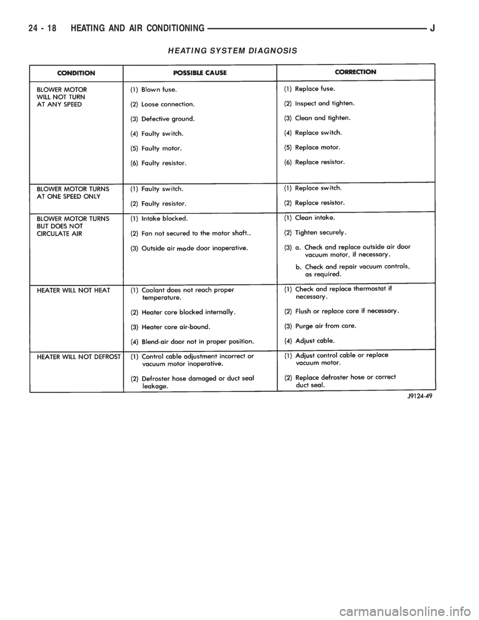
HEATING SYSTEM DIAGNOSIS
24 - 18 HEATING AND AIR CONDITIONINGJ
Page 1914 of 2198
COMPRESSOR SERVICE
DESCRIPTION
The A/C system uses a Sanden SD7H15 compres-
sor. The compressor is a 7 piston design.
The clutch used on the compressor consists of 3 ba-
sic components: the pulley and bearing hub, clutch
plate and field coil (Fig. 1). The pulley and field coil
are attached to the front of the compressor with ta-
pered snap rings. The compressor has a splined shaft
and the clutch plate is retained on the shaft with a
self-locking nut.
COMPRESSOR
REVIEW WARNINGS AND CAUTIONS IN
THIS GROUP BEFORE PROCEEDING WITH
THIS PROCEDURE.
REMOVAL
(1) Recover refrigerant from A/C system.
(2) Disconnect negative cable from battery.
(3) Disconnect the clutch lead wire.
(4) Remove the discharge and suction lines from
the compressor. Plug or tape all the openings.
(5) Remove the serpentine drive belt (refer to
Group 7, Cooling System for the proper procedure).
(6) Remove the bolts and lift the compressor from
the mounting bracket (Figs. 2 and 3).
INSTALLATION
If a replacement compressor is being in-
stalled; check the oil level. Add or subtract oil
as necessary and install the magnetic clutch on
the compressor.
(1) If the mounting bracket was removed, install
the bracket to the block. Tighten the mounting bolts
to 27 Nzm (20 ft. lbs.) torque.
(2) Install the compressor on the mounting
bracket. Tighten the bolts to 27 Nzm (20 ft. lbs.)
torque.(3) Install the serpentine drive belt (refer to Group
7, Cooling System for the proper procedure).
(4) Tighten the serpentine drive belt to the speci-
fied tension.
²New belt tensionÐ800-900 N (180-200 lb-f).
²Used belt tensionÐ623-712 N (140-160 lb-f).
(5) Remove the tape or plastic plugs from all the
suction and discharge openings and install lines on
the compressor.
(6) Connect the clutch lead wire.
(7) Connect negative cable to battery.
(8) Evacuate, charge and test the system for leaks.
Fig. 1 Compressor Clutch
Fig. 2 Compressor and Mounting Bracket (LH Drive
Vehicles)
Fig. 3 Compressor and Mounting Bracket (RH Drive
Vehicles)
JHEATING AND AIR CONDITIONING 24 - 19
Page 1915 of 2198
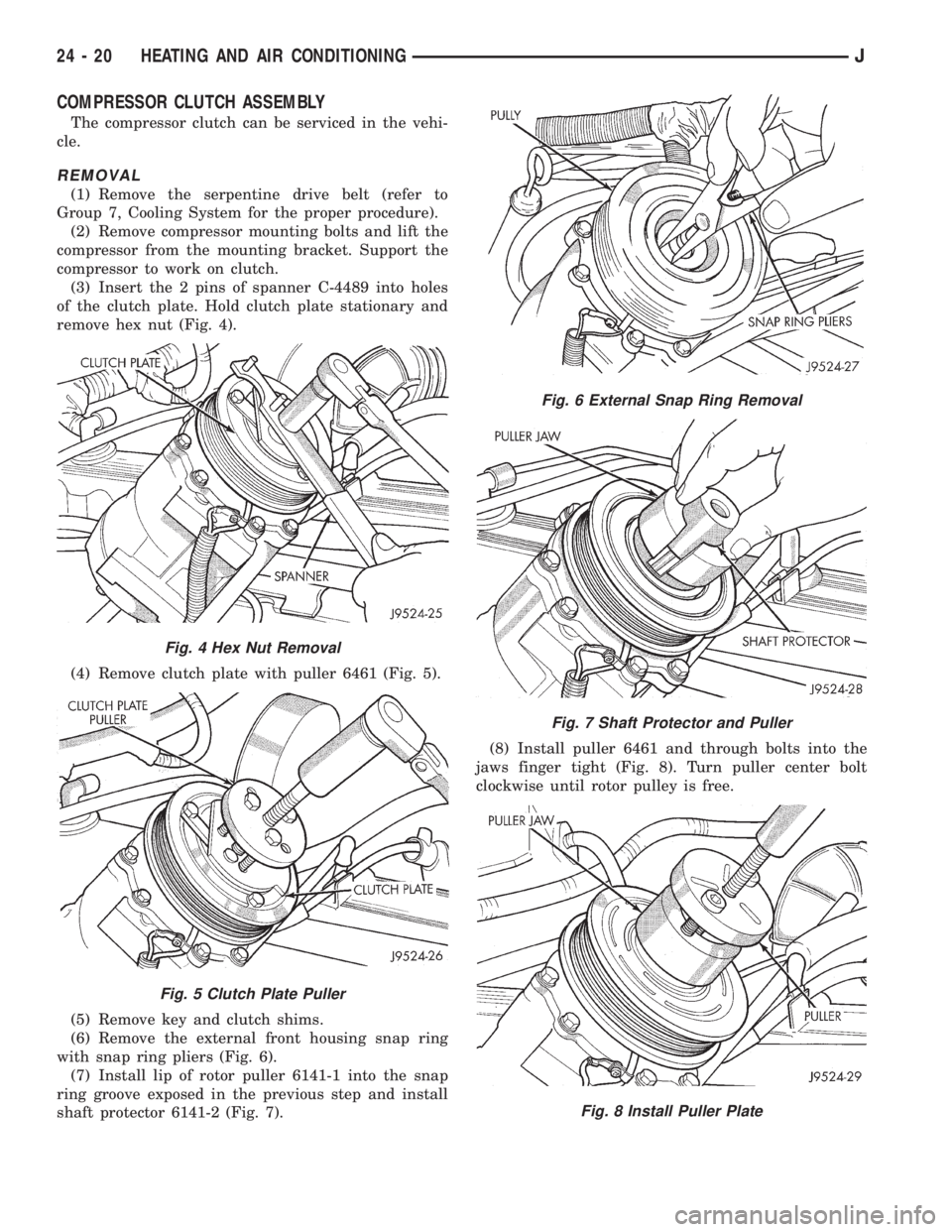
COMPRESSOR CLUTCH ASSEMBLY
The compressor clutch can be serviced in the vehi-
cle.
REMOVAL
(1) Remove the serpentine drive belt (refer to
Group 7, Cooling System for the proper procedure).
(2) Remove compressor mounting bolts and lift the
compressor from the mounting bracket. Support the
compressor to work on clutch.
(3) Insert the 2 pins of spanner C-4489 into holes
of the clutch plate. Hold clutch plate stationary and
remove hex nut (Fig. 4).
(4) Remove clutch plate with puller 6461 (Fig. 5).
(5) Remove key and clutch shims.
(6) Remove the external front housing snap ring
with snap ring pliers (Fig. 6).
(7) Install lip of rotor puller 6141-1 into the snap
ring groove exposed in the previous step and install
shaft protector 6141-2 (Fig. 7).(8) Install puller 6461 and through bolts into the
jaws finger tight (Fig. 8). Turn puller center bolt
clockwise until rotor pulley is free.
Fig. 6 External Snap Ring Removal
Fig. 7 Shaft Protector and Puller
Fig. 8 Install Puller Plate
Fig. 4 Hex Nut Removal
Fig. 5 Clutch Plate Puller
24 - 20 HEATING AND AIR CONDITIONINGJ
Page 1916 of 2198
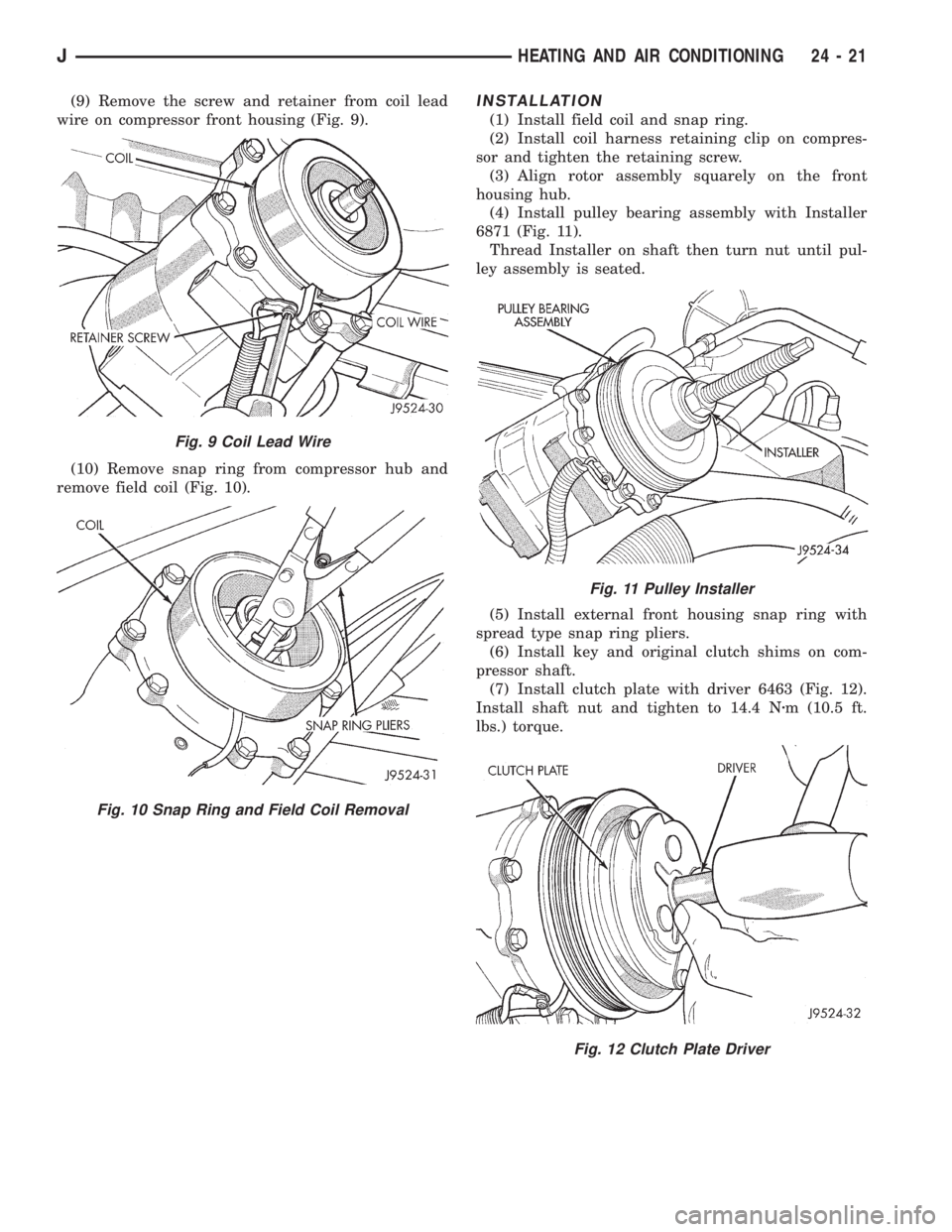
(9) Remove the screw and retainer from coil lead
wire on compressor front housing (Fig. 9).
(10) Remove snap ring from compressor hub and
remove field coil (Fig. 10).INSTALLATION
(1) Install field coil and snap ring.
(2) Install coil harness retaining clip on compres-
sor and tighten the retaining screw.
(3) Align rotor assembly squarely on the front
housing hub.
(4) Install pulley bearing assembly with Installer
6871 (Fig. 11).
Thread Installer on shaft then turn nut until pul-
ley assembly is seated.
(5) Install external front housing snap ring with
spread type snap ring pliers.
(6) Install key and original clutch shims on com-
pressor shaft.
(7) Install clutch plate with driver 6463 (Fig. 12).
Install shaft nut and tighten to 14.4 Nzm (10.5 ft.
lbs.) torque.
Fig. 9 Coil Lead Wire
Fig. 10 Snap Ring and Field Coil Removal
Fig. 11 Pulley Installer
Fig. 12 Clutch Plate Driver
JHEATING AND AIR CONDITIONING 24 - 21
Page 1917 of 2198
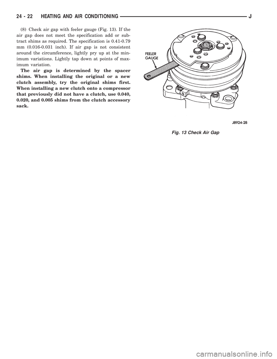
(8) Check air gap with feeler gauge (Fig. 13). If the
air gap does not meet the specification add or sub-
tract shims as required. The specification is 0.41-0.79
mm (0.016-0.031 inch). If air gap is not consistent
around the circumference, lightly pry up at the min-
imum variations. Lightly tap down at points of max-
imum variation.
The air gap is determined by the spacer
shims. When installing the original or a new
clutch assembly, try the original shims first.
When installing a new clutch onto a compressor
that previously did not have a clutch, use 0.040,
0.020, and 0.005 shims from the clutch accessory
sack.
Fig. 13 Check Air Gap
24 - 22 HEATING AND AIR CONDITIONINGJ
Page 1918 of 2198
COMPONENT SERVICEÐXJ VEHICLES
INDEX
page page
A/C Recirculating Door Vacuum Motor
Replacement........................... 27
Blower Motor Resistors Replacement.......... 31
Blower Motor/Fan Replacement............... 24
Condenser Filter DrierÐ2.5L Engines.......... 27
CondenserÐ4.0L Engines................... 28
Description.............................. 23
Evaporator Coil........................... 30
Evaporator/Blower Housing.................. 29Expansion Valve.......................... 31
Filter DrierÐ4.0L Engines................... 28
Fin Sensing Cycling Clutch Switch............. 31
Heater and A/C Control Replacement.......... 23
Heater Core............................. 26
Heater Housing Replacement................ 26
Heater/Defroster/Instrument Panel Outlet Vacuum
Motor Replacement...................... 26
DESCRIPTION
The Climate Control System combines air condi-
tioning, heating and ventilating capabilities for vehi-
cles equipped with air conditioning. Vehicles without
air conditioning perform heating and ventilating
functions without the air conditioning evaporator.
Both systems consist basically of 2 parts:
²Blower and Air Inlet Assembly
²Heater Core and Air Distribution Assembly
These unit may be removed separately from under
the instrument panel for service.
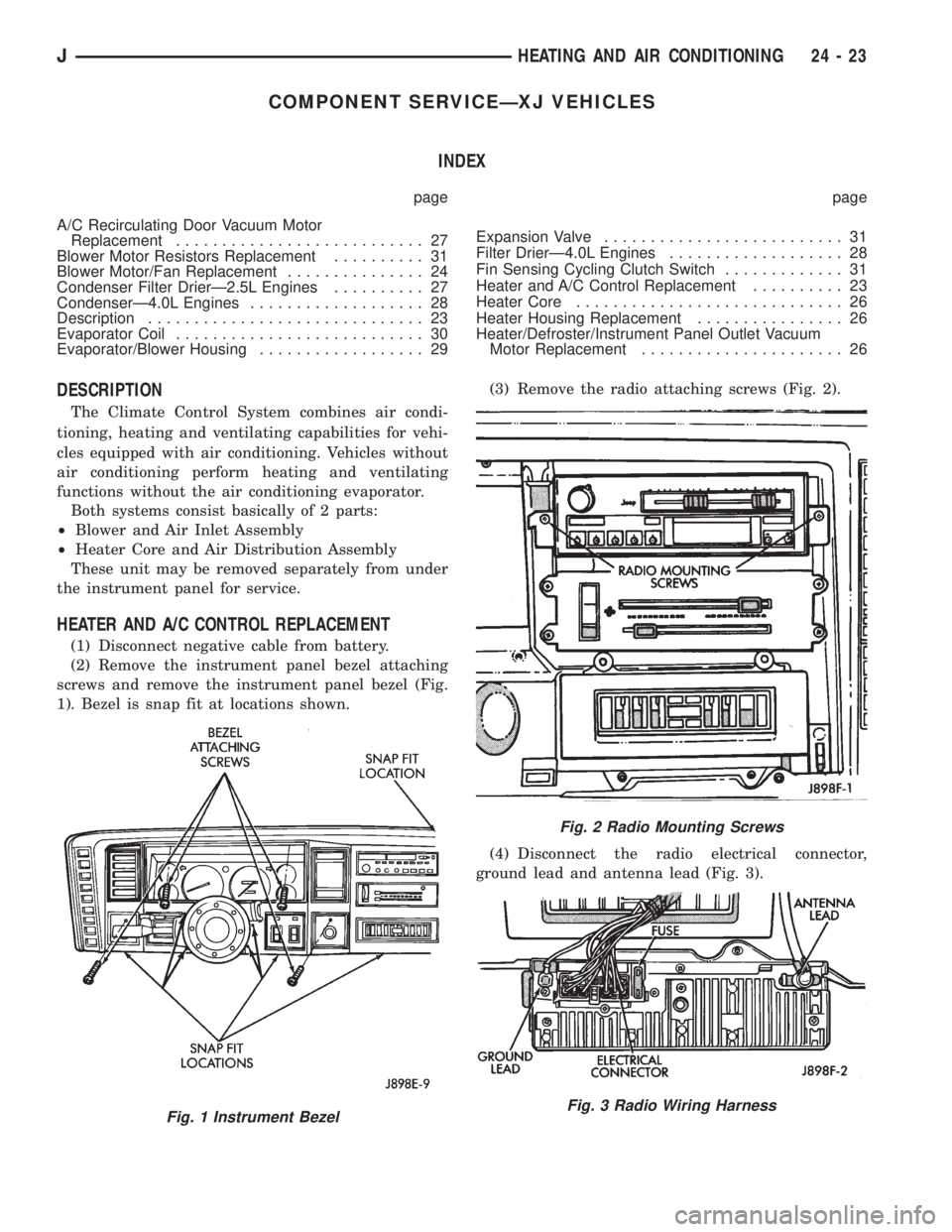
HEATER AND A/C CONTROL REPLACEMENT
(1) Disconnect negative cable from battery.
(2) Remove the instrument panel bezel attaching
screws and remove the instrument panel bezel (Fig.
1). Bezel is snap fit at locations shown.(3) Remove the radio attaching screws (Fig. 2).
(4) Disconnect the radio electrical connector,
ground lead and antenna lead (Fig. 3).
Fig. 1 Instrument Bezel
Fig. 2 Radio Mounting Screws
Fig. 3 Radio Wiring Harness
JHEATING AND AIR CONDITIONING 24 - 23
Page 1919 of 2198
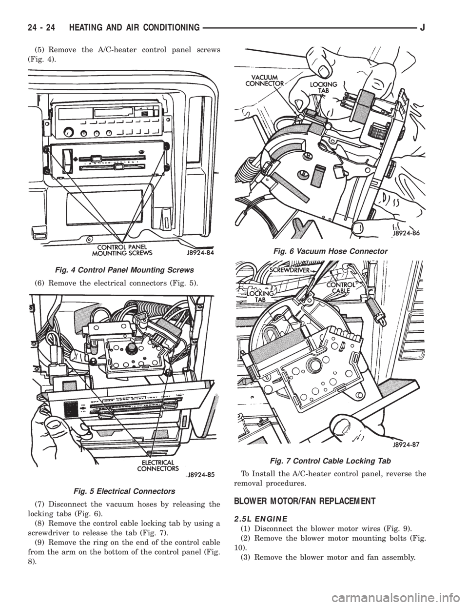
(5) Remove the A/C-heater control panel screws
(Fig. 4).
(6) Remove the electrical connectors (Fig. 5).
(7) Disconnect the vacuum hoses by releasing the
locking tabs (Fig. 6).
(8) Remove the control cable locking tab by using a
screwdriver to release the tab (Fig. 7).
(9) Remove the ring on the end of the control cable
from the arm on the bottom of the control panel (Fig.
8).To Install the A/C-heater control panel, reverse the
removal procedures.
BLOWER MOTOR/FAN REPLACEMENT
2.5L ENGINE
(1) Disconnect the blower motor wires (Fig. 9).
(2) Remove the blower motor mounting bolts (Fig.
10).
(3) Remove the blower motor and fan assembly.
Fig. 4 Control Panel Mounting Screws
Fig. 5 Electrical Connectors
Fig. 6 Vacuum Hose Connector
Fig. 7 Control Cable Locking Tab
24 - 24 HEATING AND AIR CONDITIONINGJ
Page 1920 of 2198
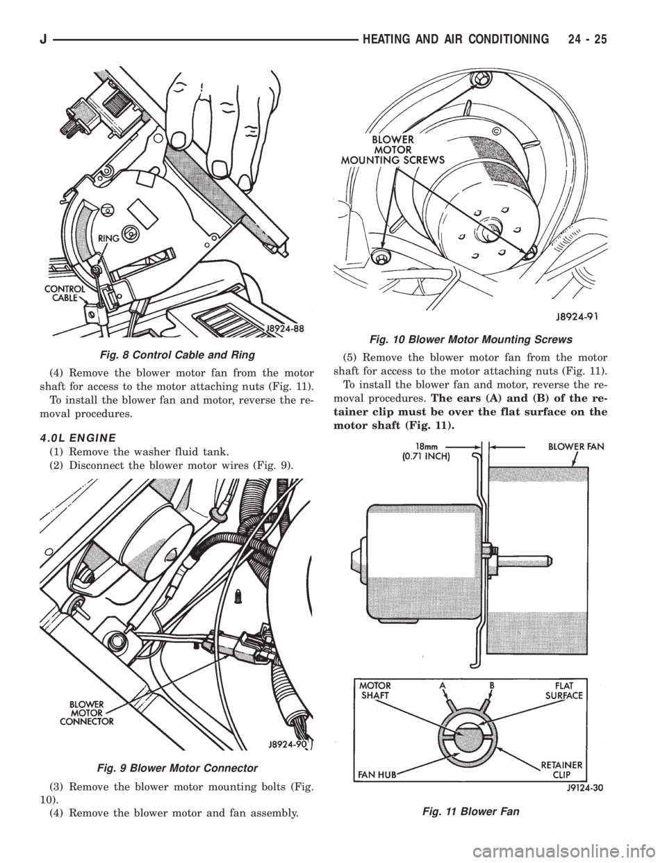
(4) Remove the blower motor fan from the motor
shaft for access to the motor attaching nuts (Fig. 11).
To install the blower fan and motor, reverse the re-
moval procedures.
4.0L ENGINE
(1) Remove the washer fluid tank.
(2) Disconnect the blower motor wires (Fig. 9).
(3) Remove the blower motor mounting bolts (Fig.
10).
(4) Remove the blower motor and fan assembly.(5) Remove the blower motor fan from the motor
shaft for access to the motor attaching nuts (Fig. 11).
To install the blower fan and motor, reverse the re-
moval procedures.The ears (A) and (B) of the re-
tainer clip must be over the flat surface on the
motor shaft (Fig. 11).
Fig. 8 Control Cable and Ring
Fig. 9 Blower Motor Connector
Fig. 10 Blower Motor Mounting Screws
Fig. 11 Blower Fan
JHEATING AND AIR CONDITIONING 24 - 25