JEEP CHEROKEE 1995 Service Repair Manual
Manufacturer: JEEP, Model Year: 1995, Model line: CHEROKEE, Model: JEEP CHEROKEE 1995Pages: 2198, PDF Size: 82.83 MB
Page 1881 of 2198
CAUTION: Be prepared to install the windshield
glass immediately after applying the adhesive. The
adhesive begins to cure within 10-15 minutes.
(12) Align the windshield with the grease pencil
marks (or the tape strips) and position windshield on
frame flanges.
(13) Force the windshield glass inward just enough
to wet-out and set urethane. Use care to avoid exces-
sive squeeze-out of adhesive.
(14) Water test the windshield with a cold water
spray after installation. Do not direct high pressure
streams of water directly at the urethane. Use a
moderate spray only. If any leaks are detected, apply
urethane as necessary.
(15) Install the windshield reveal molding and (if
used) remove the masking tape from the inner sur-
face of the glass.
(16) Install all removed components and clean the
vehicle. If necessary, refer to the applicable installa-
tion procedures.
(17) Open windows and liftgate to prevent pres-
sure build-up while the urethane is curing.
(18) Install the rearview mirror on the bracket and
tighten the mirror setscrew with 2 Nzm (15 in-lbs)
torque.
INSTALLATIONÐEXTENDED METHOD
Normally, after a windshield is installed, the rear-
view mirror bracket also requires installation.Do
not install the bracket until after the wind-
shield installation is completed.
(1) Remove all of the original urethane from all the
frame pinchweld flanges. Use an electric hot knife
and a plow-type knife blade to remove the adhesive.
(2) Inspect and repair the windshield frame and
the pinchweld flanges as necessary.
(3) Inspect and replace the reveal molding if the
retainers are damaged.
(4) Prime the frame pinchweld flanges with a ure-
thane base primer. However, if the flange is top-
coated with paint, prime the flanges with a paint
finish primer.This is important because ure-
thane adhesive will not adhere to all top coat
paints.
(5) Install the replacement interior trim molding
(Fig. 5) on the frame pinchweld flanges (Fig. 5).
(6) Install and inspect the fit of the windshield
glass on the pinchweld flanges according to the fol-
lowing instructions:
²Position the windshield glass on the flanges and
adjust the position until it is correctly aligned within
the windshield frame.
²Measure the gap between the frame and the glass
around the entire perimeter of the glass and the
flange.
²The gap should be at least 3 mm (1/8 in) but no
more than 6 mm (1/4 in) at any point around the pe-rimeter, and the flanges should be in complete con-
tact with the glass around the perimeter of the
frame.
(7) If the pinchweld flanges require repair, remove
the windshield glass and straighten, align, or repair
the flange(s) as necessary.
(8) Position the windshield on the flanges and in-
spect the windshield fit again. If the fit is acceptable,
mark windshield final position on the glass and the
frame. The marks (or masking tape) will be used for
installation alignment reference.
(9) If the replacement windshield glass does not
have blackout primer:
²Attach a 25-mm (1-in) wide masking tape band
around the interior side of the glass 16 mm (5/8 in)
from the edge of the glass (Fig. 6).
²Attach the tape only to the interior side of
the glass.
²Thoroughly mix and apply blackout primer to the
16 mm (5/8 in) surface area around the interior side
of the glass (Fig. 6).
²Allow the primer to dry for at least 10-12 minutes.
(10) Cut the urethane adhesive applicator nozzle
(Fig. 7).
(11) Apply a 3-mm (1/8-in) diameter bead of ure-
thane to the surface area.
CAUTION: Be prepared to install the windshield
glass immediately after applying the adhesive. The
adhesive begins to cure within 10-15 minutes.
(12) Align windshield with reference marks (or the
tape strips) and position it on the frame pinchweld
flanges.
(13) Force the windshield glass inward just enough
to wet-out and set urethane. Use care to avoid exces-
sive squeeze-out of adhesive.
(14) Water test the windshield with a cold water
spray after installation. Do not direct high pressure
streams of water directly at the urethane. Use a
moderate spray only. If any leaks are detected, apply
urethane as necessary.
(15) Install the windshield reveal molding and (if
used) remove the masking tape from the inner sur-
face of the glass.
(16) Install all the other previously removed com-
ponents and clean the vehicle. If necessary, refer to
the applicable installation procedures.
(17) Open windows and liftgate to prevent pres-
sure build-up while the urethane is curing.
(18) Install the rearview mirror on the bracket and
tighten the mirror setscrew to 2 Nzm (15 in-lbs)
torque.
23 - 148 STATIONARY GLASSÐYJJ
Page 1882 of 2198
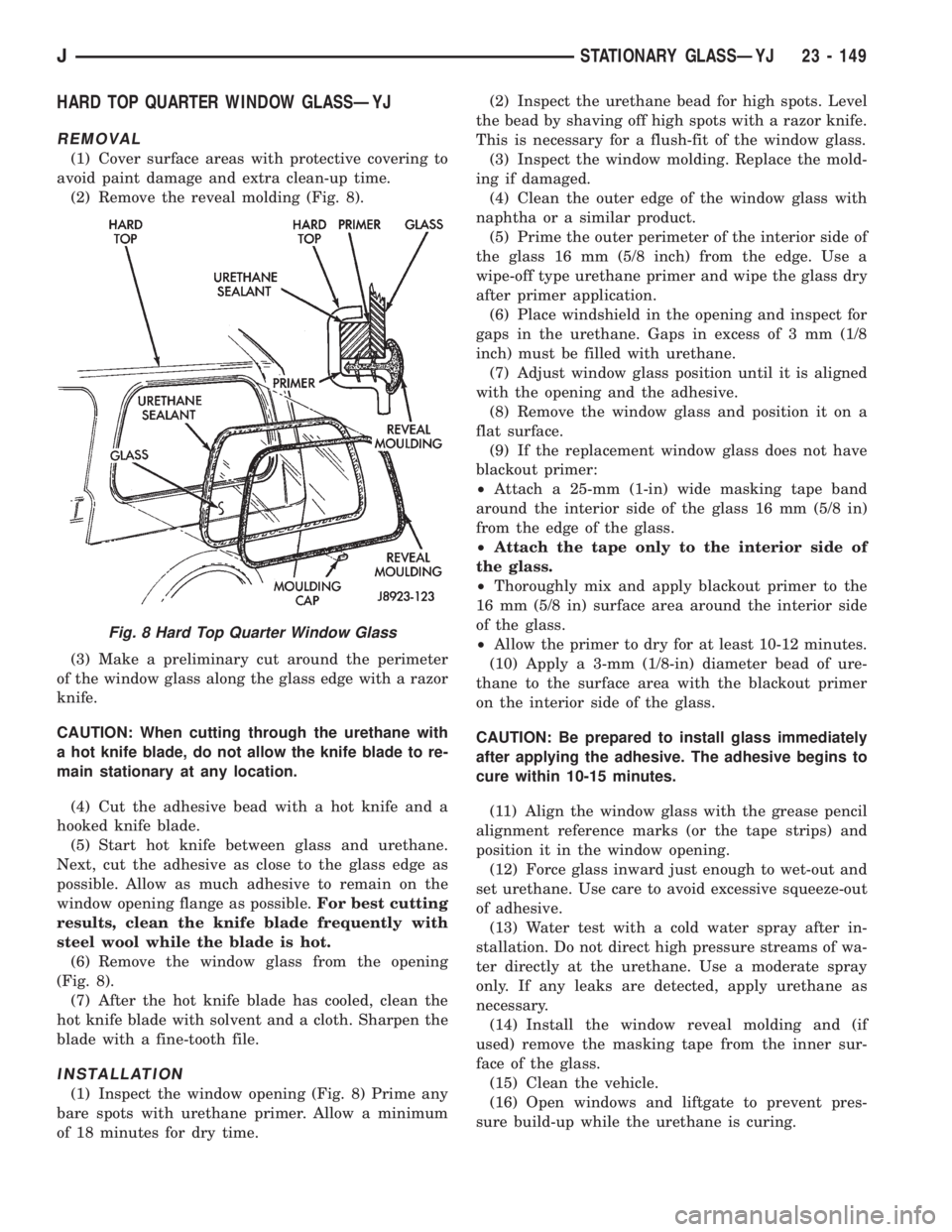
HARD TOP QUARTER WINDOW GLASSÐYJ
REMOVAL
(1) Cover surface areas with protective covering to
avoid paint damage and extra clean-up time.
(2) Remove the reveal molding (Fig. 8).
(3) Make a preliminary cut around the perimeter
of the window glass along the glass edge with a razor
knife.
CAUTION: When cutting through the urethane with
a hot knife blade, do not allow the knife blade to re-
main stationary at any location.
(4) Cut the adhesive bead with a hot knife and a
hooked knife blade.
(5) Start hot knife between glass and urethane.
Next, cut the adhesive as close to the glass edge as
possible. Allow as much adhesive to remain on the
window opening flange as possible.For best cutting
results, clean the knife blade frequently with
steel wool while the blade is hot.
(6) Remove the window glass from the opening
(Fig. 8).
(7) After the hot knife blade has cooled, clean the
hot knife blade with solvent and a cloth. Sharpen the
blade with a fine-tooth file.
INSTALLATION
(1) Inspect the window opening (Fig. 8) Prime any
bare spots with urethane primer. Allow a minimum
of 18 minutes for dry time.(2) Inspect the urethane bead for high spots. Level
the bead by shaving off high spots with a razor knife.
This is necessary for a flush-fit of the window glass.
(3) Inspect the window molding. Replace the mold-
ing if damaged.
(4) Clean the outer edge of the window glass with
naphtha or a similar product.
(5) Prime the outer perimeter of the interior side of
the glass 16 mm (5/8 inch) from the edge. Use a
wipe-off type urethane primer and wipe the glass dry
after primer application.
(6) Place windshield in the opening and inspect for
gaps in the urethane. Gaps in excess of 3 mm (1/8
inch) must be filled with urethane.
(7) Adjust window glass position until it is aligned
with the opening and the adhesive.
(8) Remove the window glass and position it on a
flat surface.
(9) If the replacement window glass does not have
blackout primer:
²Attach a 25-mm (1-in) wide masking tape band
around the interior side of the glass 16 mm (5/8 in)
from the edge of the glass.
²Attach the tape only to the interior side of
the glass.
²Thoroughly mix and apply blackout primer to the
16 mm (5/8 in) surface area around the interior side
of the glass.
²Allow the primer to dry for at least 10-12 minutes.
(10) Apply a 3-mm (1/8-in) diameter bead of ure-
thane to the surface area with the blackout primer
on the interior side of the glass.
CAUTION: Be prepared to install glass immediately
after applying the adhesive. The adhesive begins to
cure within 10-15 minutes.
(11) Align the window glass with the grease pencil
alignment reference marks (or the tape strips) and
position it in the window opening.
(12) Force glass inward just enough to wet-out and
set urethane. Use care to avoid excessive squeeze-out
of adhesive.
(13) Water test with a cold water spray after in-
stallation. Do not direct high pressure streams of wa-
ter directly at the urethane. Use a moderate spray
only. If any leaks are detected, apply urethane as
necessary.
(14) Install the window reveal molding and (if
used) remove the masking tape from the inner sur-
face of the glass.
(15) Clean the vehicle.
(16) Open windows and liftgate to prevent pres-
sure build-up while the urethane is curing.
Fig. 8 Hard Top Quarter Window Glass
JSTATIONARY GLASSÐYJ 23 - 149
Page 1883 of 2198
STATIONARY GLASS WATER LEAK DETECTION
AND REPAIRÐYJ
The sources of water leaks around windshield/win-
dow glass can be sealed without removing the wind-
shield/window glass. If the glass is firmly bonded and
only has a small leak, seal areas with a liquid butyl
sealant. However, if weatherstrip seal or urethane
sealant has large breaks, a urethane sealant must be
used.
LEAK TEST
Water test the windshield/window with a spray
only.Do not use hard streams of water.Work
from the bottom to the top of the windshield/window.
Water test the windshield/window with a spray
only.Do not use hard streams of water.Work
from the bottom to the top of the windshield/window
glass.
If a water leak exists between the glass and weath-
erstrip seal (or between the seal and a body flange):
²Push the glass outward at the leak area, and de-
termine the extent of the gap.
Push the glass outward while a helper sprays the
windshield/window glass with water.
SEALING MINOR LEAK AREAS
(1) Thoroughly clean and remove all foreign mate-
rial from the leak area. Dry the area with com-
pressed air.
(2) Seal the leak area with butyl sealant. Allow the
sealant to cure for at least 1/2 hour. Next, water test
the glass to ensure that the leak area is sealed.
SEALING MAJOR LEAK AREAS
(1) Thoroughly clean the leak area.
(2) As applicable, apply primer to either glass or
weatherstrip seal leak area. Use blackout primer on
the glass and urethane primer on the weatherstrip
seal.
(3) Apply urethane to the leak area. Use an adhe-
sive cartridge with a pointed nozzle.
(4) Water test glass immediately with cold water
spray. Allow the water to spill over the edge of glass
and weatherstrip seal.
(5) Apply additional adhesive, if necessary.
(6) Remove any excess adhesive.
23 - 150 STATIONARY GLASSÐYJJ
Page 1884 of 2198
INTERIOR COMPONENTS
INDEX
page page
Add-A-TrunkÐYJ........................ 157
Bucket SeatsÐYJ........................ 153
CarpetÐYJ............................. 156
Floor ConsolesÐYJ...................... 155
Front Shoulder BeltsÐYJ.................. 154
Glove BoxÐYJ.......................... 152
Instrument Cluster and Gauge HousingsÐYJ.... 151Instrument Cluster BezelÐYJ............... 151
Instrument Panel ComponentsÐYJ........... 152
Instrument PanelÐYJ..................... 151
Rear Bench SeatÐYJ..................... 153
Rear Shoulder BeltsÐYJ................... 154
SeatsÐYJ............................. 153
SunvisorsÐYJ.......................... 155
INSTRUMENT PANELÐYJ
The instrument panel is constructed of sheet metal
and is attached to cowl panel with screws. The in-
strument panel and defroster grille pad is attached
to the instrument panel with screws.
INSTRUMENT CLUSTER AND GAUGE HOUSINGSÐ
YJ
REMOVAL
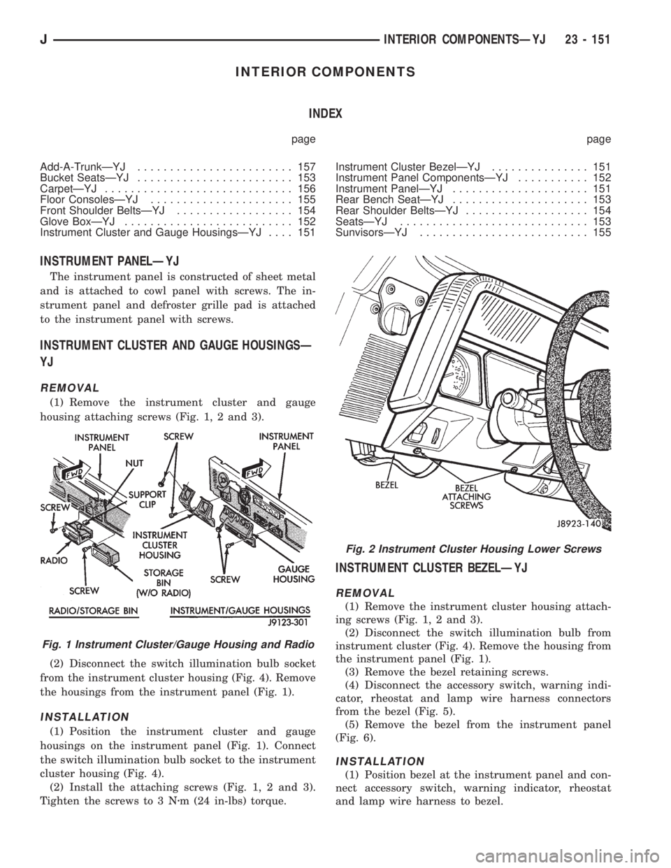
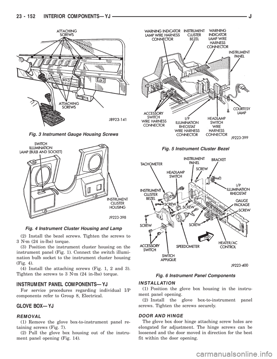
(1) Remove the instrument cluster and gauge
housing attaching screws (Fig. 1, 2 and 3).
(2) Disconnect the switch illumination bulb socket
from the instrument cluster housing (Fig. 4). Remove
the housings from the instrument panel (Fig. 1).
INSTALLATION
(1) Position the instrument cluster and gauge
housings on the instrument panel (Fig. 1). Connect
the switch illumination bulb socket to the instrument
cluster housing (Fig. 4).
(2) Install the attaching screws (Fig. 1, 2 and 3).
Tighten the screws to 3 Nzm (24 in-lbs) torque.
INSTRUMENT CLUSTER BEZELÐYJ
REMOVAL
(1) Remove the instrument cluster housing attach-
ing screws (Fig. 1, 2 and 3).
(2) Disconnect the switch illumination bulb from
instrument cluster (Fig. 4). Remove the housing from
the instrument panel (Fig. 1).
(3) Remove the bezel retaining screws.
(4) Disconnect the accessory switch, warning indi-
cator, rheostat and lamp wire harness connectors
from the bezel (Fig. 5).
(5) Remove the bezel from the instrument panel
(Fig. 6).
INSTALLATION
(1) Position bezel at the instrument panel and con-
nect accessory switch, warning indicator, rheostat
and lamp wire harness to bezel.
Fig. 1 Instrument Cluster/Gauge Housing and Radio
Fig. 2 Instrument Cluster Housing Lower Screws
JINTERIOR COMPONENTSÐYJ 23 - 151
Page 1885 of 2198
(2) Install the bezel screws. Tighten the screws to
3Nzm (24 in-lbs) torque.
(3) Position the instrument cluster housing on the
instrument panel (Fig. 1). Connect the switch illumi-
nation bulb socket to the instrument cluster housing
(Fig. 4).
(4) Install the attaching screws (Fig. 1, 2 and 3).
Tighten the screws to 3 Nzm (24 in-lbs) torque.
INSTRUMENT PANEL COMPONENTSÐYJ
For service procedures regarding individual I/P
components refer to Group 8, Electrical.
GLOVE BOXÐYJ
REMOVAL
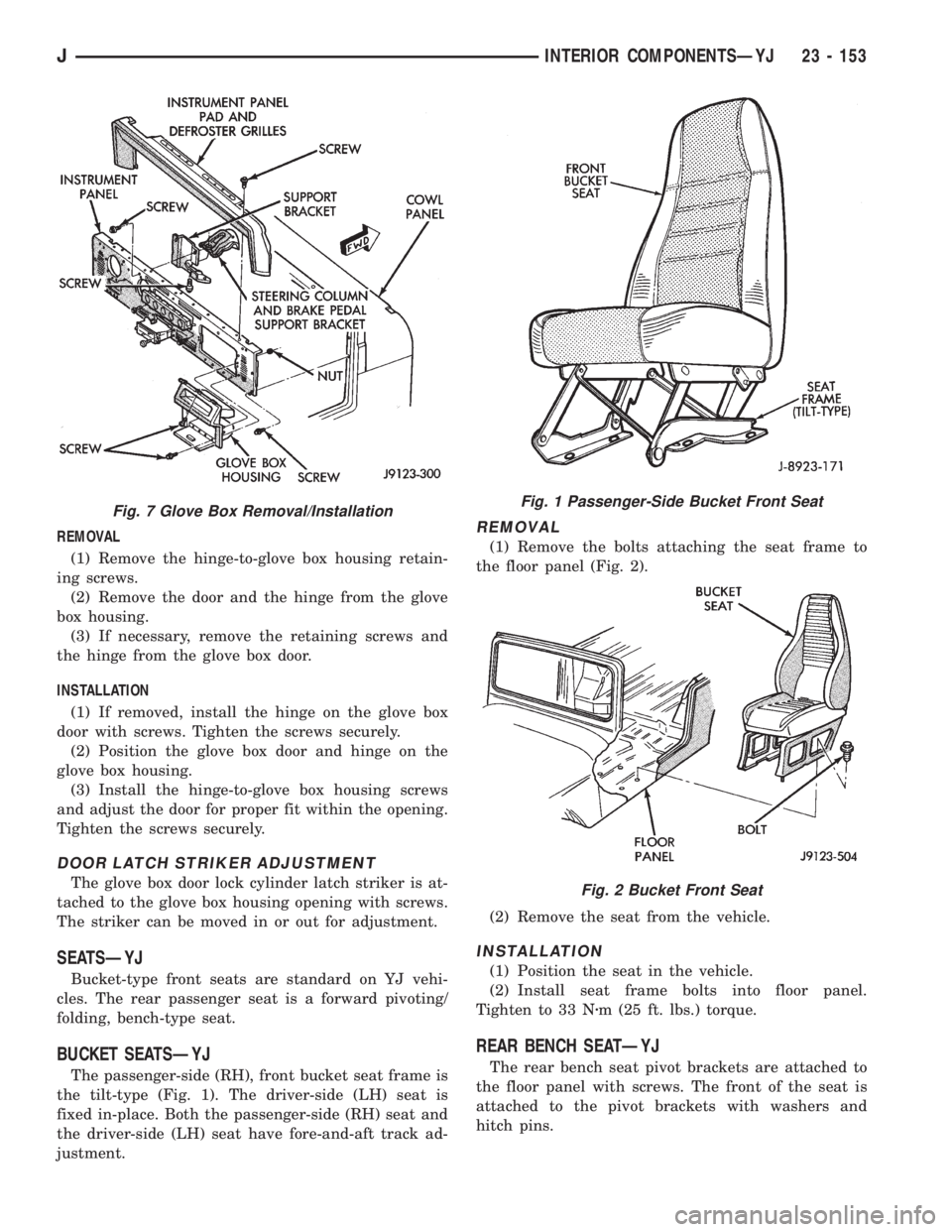
(1) Remove the glove box-to-instrument panel re-
taining screws (Fig. 7).
(2) Pull the glove box housing out of the instru-
ment panel opening (Fig. 14).
INSTALLATION
(1) Position the glove box housing in the instru-
ment panel opening.
(2) Install the glove box-to-instrument panel
screws. Tighten the screws securely.
DOOR AND HINGE
The glove box door hinge attaching screw holes are
elongated for adjustment. The hinge screws can be
loosened and the door moved in direction for the best
fit within the door opening.
Fig. 3 Instrument Gauge Housing Screws
Fig. 4 Instrument Cluster Housing and Lamp
Fig. 5 Instrument Cluster Bezel
Fig. 6 Instrument Panel Components
23 - 152 INTERIOR COMPONENTSÐYJJ
Page 1886 of 2198
REMOVAL
(1) Remove the hinge-to-glove box housing retain-
ing screws.
(2) Remove the door and the hinge from the glove
box housing.
(3) If necessary, remove the retaining screws and
the hinge from the glove box door.
INSTALLATION
(1) If removed, install the hinge on the glove box
door with screws. Tighten the screws securely.
(2) Position the glove box door and hinge on the
glove box housing.
(3) Install the hinge-to-glove box housing screws
and adjust the door for proper fit within the opening.
Tighten the screws securely.
DOOR LATCH STRIKER ADJUSTMENT
The glove box door lock cylinder latch striker is at-
tached to the glove box housing opening with screws.
The striker can be moved in or out for adjustment.
SEATSÐYJ
Bucket-type front seats are standard on YJ vehi-
cles. The rear passenger seat is a forward pivoting/
folding, bench-type seat.
BUCKET SEATSÐYJ
The passenger-side (RH), front bucket seat frame is
the tilt-type (Fig. 1). The driver-side (LH) seat is
fixed in-place. Both the passenger-side (RH) seat and
the driver-side (LH) seat have fore-and-aft track ad-
justment.
REMOVAL
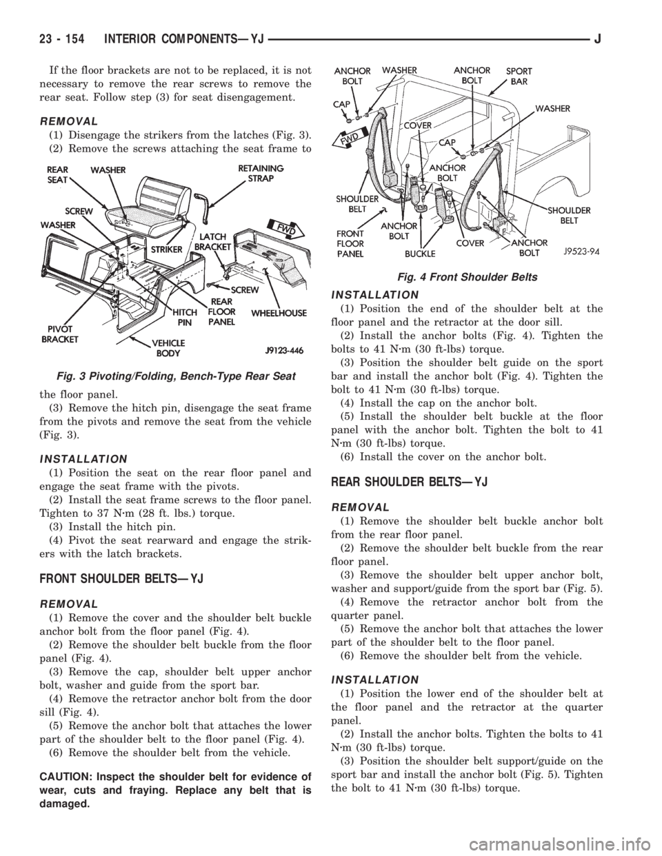
(1) Remove the bolts attaching the seat frame to
the floor panel (Fig. 2).
(2) Remove the seat from the vehicle.
INSTALLATION
(1) Position the seat in the vehicle.
(2) Install seat frame bolts into floor panel.
Tighten to 33 Nzm (25 ft. lbs.) torque.
REAR BENCH SEATÐYJ
The rear bench seat pivot brackets are attached to
the floor panel with screws. The front of the seat is
attached to the pivot brackets with washers and
hitch pins.
Fig. 7 Glove Box Removal/InstallationFig. 1 Passenger-Side Bucket Front Seat
Fig. 2 Bucket Front Seat
JINTERIOR COMPONENTSÐYJ 23 - 153
Page 1887 of 2198
If the floor brackets are not to be replaced, it is not
necessary to remove the rear screws to remove the
rear seat. Follow step (3) for seat disengagement.
REMOVAL
(1) Disengage the strikers from the latches (Fig. 3).
(2) Remove the screws attaching the seat frame to
the floor panel.
(3) Remove the hitch pin, disengage the seat frame
from the pivots and remove the seat from the vehicle
(Fig. 3).
INSTALLATION
(1) Position the seat on the rear floor panel and
engage the seat frame with the pivots.
(2) Install the seat frame screws to the floor panel.
Tighten to 37 Nzm (28 ft. lbs.) torque.
(3) Install the hitch pin.
(4) Pivot the seat rearward and engage the strik-
ers with the latch brackets.
FRONT SHOULDER BELTSÐYJ
REMOVAL
(1) Remove the cover and the shoulder belt buckle
anchor bolt from the floor panel (Fig. 4).
(2) Remove the shoulder belt buckle from the floor
panel (Fig. 4).
(3) Remove the cap, shoulder belt upper anchor
bolt, washer and guide from the sport bar.
(4) Remove the retractor anchor bolt from the door
sill (Fig. 4).
(5) Remove the anchor bolt that attaches the lower
part of the shoulder belt to the floor panel (Fig. 4).
(6) Remove the shoulder belt from the vehicle.
CAUTION: Inspect the shoulder belt for evidence of
wear, cuts and fraying. Replace any belt that is
damaged.
INSTALLATION
(1) Position the end of the shoulder belt at the
floor panel and the retractor at the door sill.
(2) Install the anchor bolts (Fig. 4). Tighten the
bolts to 41 Nzm (30 ft-lbs) torque.
(3) Position the shoulder belt guide on the sport
bar and install the anchor bolt (Fig. 4). Tighten the
bolt to 41 Nzm (30 ft-lbs) torque.
(4) Install the cap on the anchor bolt.
(5) Install the shoulder belt buckle at the floor
panel with the anchor bolt. Tighten the bolt to 41
Nzm (30 ft-lbs) torque.
(6) Install the cover on the anchor bolt.
REAR SHOULDER BELTSÐYJ
REMOVAL
(1) Remove the shoulder belt buckle anchor bolt
from the rear floor panel.
(2) Remove the shoulder belt buckle from the rear
floor panel.
(3) Remove the shoulder belt upper anchor bolt,
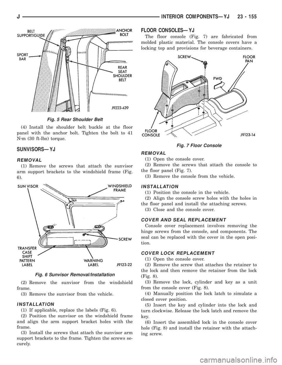
washer and support/guide from the sport bar (Fig. 5).
(4) Remove the retractor anchor bolt from the
quarter panel.
(5) Remove the anchor bolt that attaches the lower
part of the shoulder belt to the floor panel.
(6) Remove the shoulder belt from the vehicle.
INSTALLATION
(1) Position the lower end of the shoulder belt at
the floor panel and the retractor at the quarter
panel.
(2) Install the anchor bolts. Tighten the bolts to 41
Nzm (30 ft-lbs) torque.
(3) Position the shoulder belt support/guide on the
sport bar and install the anchor bolt (Fig. 5). Tighten
the bolt to 41 Nzm (30 ft-lbs) torque.
Fig. 3 Pivoting/Folding, Bench-Type Rear Seat
Fig. 4 Front Shoulder Belts
23 - 154 INTERIOR COMPONENTSÐYJJ
Page 1888 of 2198
(4) Install the shoulder belt buckle at the floor
panel with the anchor bolt. Tighten the bolt to 41
Nzm (30 ft-lbs) torque.
SUNVISORSÐYJ
REMOVAL
(1) Remove the screws that attach the sunvisor
arm support brackets to the windshield frame (Fig.
6).
(2) Remove the sunvisor from the windshield
frame.
(3) Remove the sunvisor from the vehicle.
INSTALLATION
(1) If applicable, replace the labels (Fig. 6).
(2) Position the sunvisor on the windshield frame
and align the arm support bracket holes with the
frame.
(3) Install the screws that attach the sunvisor arm
support brackets to the frame. Tighten the screws se-
curely.
FLOOR CONSOLESÐYJ
The floor console (Fig. 7) are fabricated from
molded plastic material. The console covers have a
locking top and provisions for beverage containers.
REMOVAL
(1) Open the console cover.
(2) Remove the screws that attach the console to
the floor panel (Fig. 7).
(3) Remove the console from the vehicle.
INSTALLATION
(1) Position the console in the vehicle.
(2) Align the console screw holes with the holes in
the floor panel and install the attaching screws.
(3) Close and the console cover.
COVER AND SEAL REPLACEMENT
Console cover replacement involves removing the
hinge screws from the console, and components. The
seal can be replaced with the cover in the open posi-
tion.
COVER LOCK REPLACEMENT
(1) Open the console cover.
(2) Remove the screw that attaches the retainer to
the lock and then remove the retainer from the lock
(Fig. 8).
(3) Remove the lock, cylinder and key as a unit
from the console cover (Fig. 8).
(4) Manually position the lock latch to simulate a
closed cover position.
(5) Insert the key and cylinder into the lock and
turn clockwise. Release the lock latch and remove the
key.
(6) Insert the assembled lock in the console cover
hole (Fig. 8) and install the retainer with the attach-
ing screw.
Fig. 5 Rear Shoulder Belt
Fig. 6 Sunvisor Removal/Installation
Fig. 7 Floor Console
JINTERIOR COMPONENTSÐYJ 23 - 155
Page 1889 of 2198
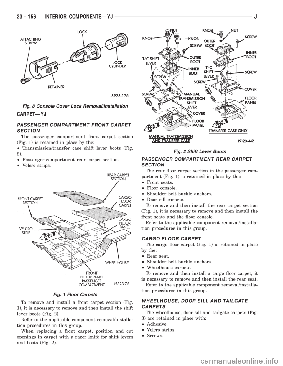
CARPETÐYJ
PASSENGER COMPARTMENT FRONT CARPET
SECTION
The passenger compartment front carpet section
(Fig. 1) is retained in place by the:
²Transmission/transfer case shift lever boots (Fig.
2).
²Passenger compartment rear carpet section.
²Velcro strips.
To remove and install a front carpet section (Fig.
1), it is necessary to remove and then install the shift
lever boots (Fig. 2).
Refer to the applicable component removal/installa-
tion procedures in this group.
When replacing a front carpet, position and cut
openings in carpet with a razor knife for shift levers
and boots (Fig. 2).
PASSENGER COMPARTMENT REAR CARPET
SECTION
The rear floor carpet section in the passenger com-
partment (Fig. 1) is retained in place by the:
²Front seats.
²Floor console.
²Shoulder belt buckle anchors.
²Door sill carpets.
To remove and then install the rear carpet section
(Fig. 1), it is necessary to remove and then install the
front seats and the floor console.
Refer to the applicable component removal/installa-
tion procedures in this group.
CARGO FLOOR CARPET
The cargo floor carpet (Fig. 1) is retained in place
by the:
²Rear seat.
²Shoulder belt buckle anchors.
²Wheelhouse carpets.
To remove and then install a cargo floor carpet, it
is necessary to remove and then install the rear seat.
Refer to the applicable component removal/installa-
tion procedures in this group.
WHEELHOUSE, DOOR SILL AND TAILGATE
CARPETS
The wheelhouse, door sill and tailgate carpets (Fig.
3) are retained in place with:
²Adhesive.
²Velcro strips.
²Screws.
Fig. 8 Console Cover Lock Removal/Installation
Fig. 1 Floor Carpets
Fig. 2 Shift Lever Boots
23 - 156 INTERIOR COMPONENTSÐYJJ
Page 1890 of 2198
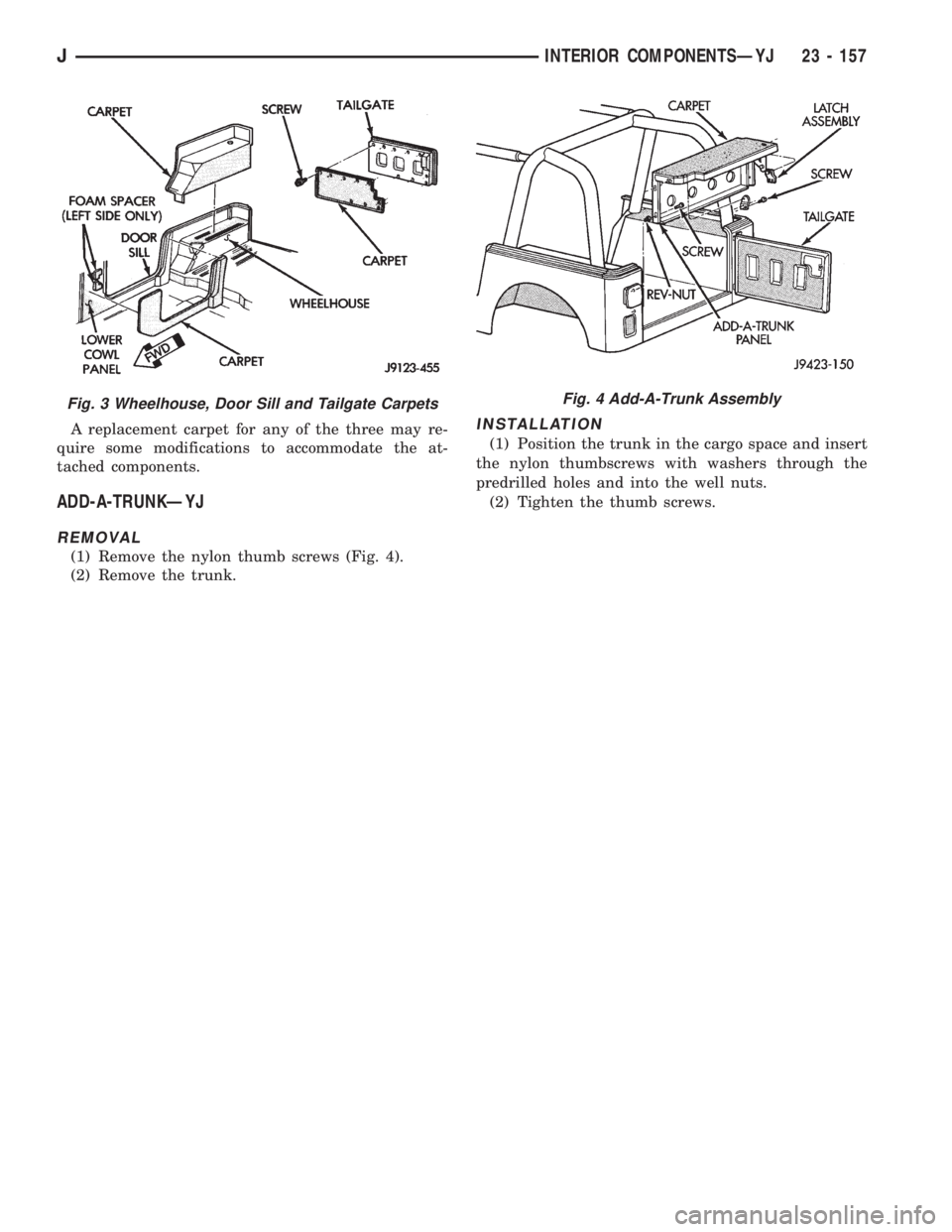
A replacement carpet for any of the three may re-
quire some modifications to accommodate the at-
tached components.
ADD-A-TRUNKÐYJ
REMOVAL
(1) Remove the nylon thumb screws (Fig. 4).
(2) Remove the trunk.
INSTALLATION
(1) Position the trunk in the cargo space and insert
the nylon thumbscrews with washers through the
predrilled holes and into the well nuts.
(2) Tighten the thumb screws.
Fig. 3 Wheelhouse, Door Sill and Tailgate CarpetsFig. 4 Add-A-Trunk Assembly
JINTERIOR COMPONENTSÐYJ 23 - 157