JEEP CHEROKEE 1995 Service Repair Manual
Manufacturer: JEEP, Model Year: 1995, Model line: CHEROKEE, Model: JEEP CHEROKEE 1995Pages: 2198, PDF Size: 82.83 MB
Page 1831 of 2198
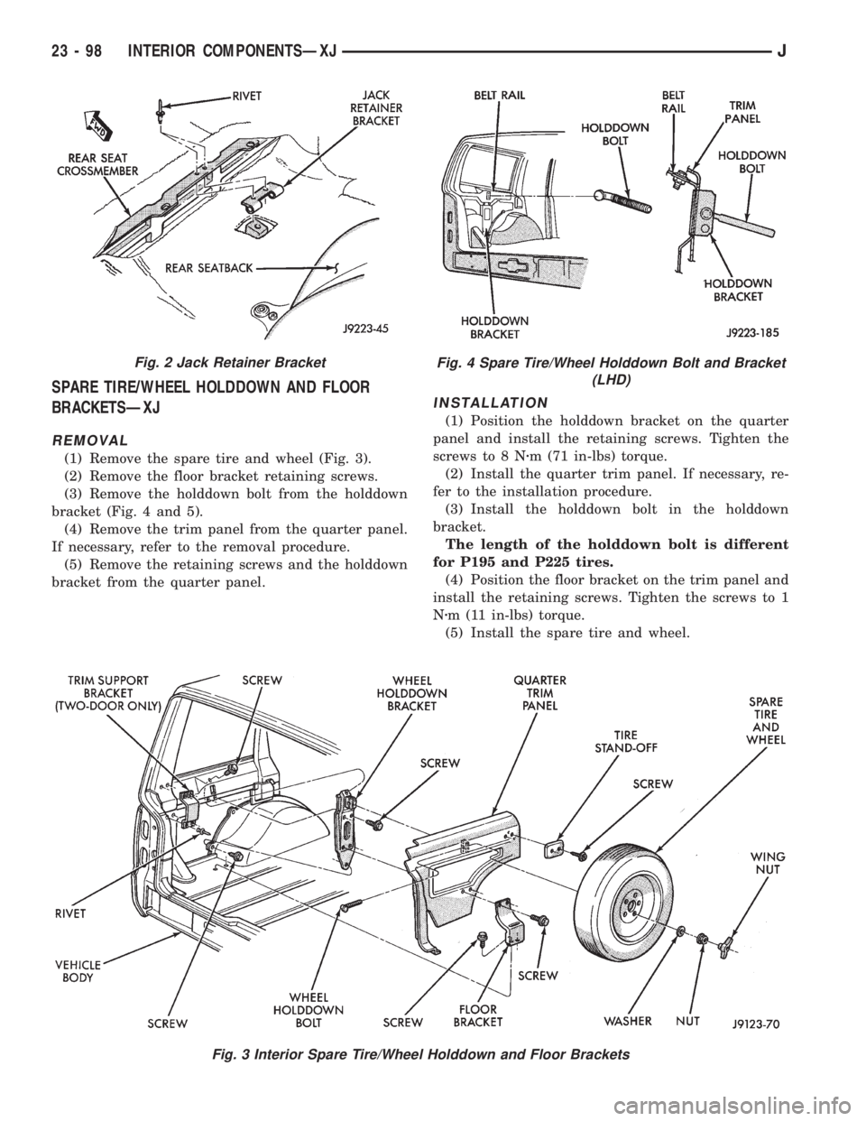
SPARE TIRE/WHEEL HOLDDOWN AND FLOOR
BRACKETSÐXJ
REMOVAL
(1) Remove the spare tire and wheel (Fig. 3).
(2) Remove the floor bracket retaining screws.
(3) Remove the holddown bolt from the holddown
bracket (Fig. 4 and 5).
(4) Remove the trim panel from the quarter panel.
If necessary, refer to the removal procedure.
(5) Remove the retaining screws and the holddown
bracket from the quarter panel.
INSTALLATION
(1) Position the holddown bracket on the quarter
panel and install the retaining screws. Tighten the
screws to 8 Nzm (71 in-lbs) torque.
(2) Install the quarter trim panel. If necessary, re-
fer to the installation procedure.
(3) Install the holddown bolt in the holddown
bracket.
The length of the holddown bolt is different
for P195 and P225 tires.
(4) Position the floor bracket on the trim panel and
install the retaining screws. Tighten the screws to 1
Nzm (11 in-lbs) torque.
(5) Install the spare tire and wheel.
Fig. 3 Interior Spare Tire/Wheel Holddown and Floor Brackets
Fig. 2 Jack Retainer BracketFig. 4 Spare Tire/Wheel Holddown Bolt and Bracket
(LHD)
23 - 98 INTERIOR COMPONENTSÐXJJ
Page 1832 of 2198
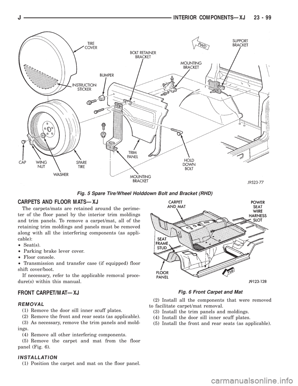
CARPETS AND FLOOR MATSÐXJ
The carpets/mats are retained around the perime-
ter of the floor panel by the interior trim moldings
and trim panels. To remove a carpet/mat, all of the
retaining trim moldings and panels must be removed
along with all the interfering components (as appli-
cable):
²Seat(s).
²Parking brake lever cover.
²Floor console.
²Transmission and transfer case (if equipped) floor
shift cover/boot.
If necessary, refer to the applicable removal proce-
dure(s) within this manual.
FRONT CARPET/MATÐXJ
REMOVAL
(1) Remove the door sill inner scuff plates.
(2) Remove the front and rear seats (as applicable).
(3) As necessary, remove the trim panels and mold-
ings.
(4) Remove all other interfering components.
(5) Remove the carpet and mat from the floor
panel (Fig. 6).
INSTALLATION
(1) Position the carpet and mat on the floor panel.(2) Install all the components that were removed
to facilitate carpet/mat removal.
(3) Install the trim panels and moldings.
(4) Install the door sill inner scuff plates.
(5) Install the front and rear seats (as applicable).
Fig. 5 Spare Tire/Wheel Holddown Bolt and Bracket (RHD)
Fig. 6 Front Carpet and Mat
JINTERIOR COMPONENTSÐXJ 23 - 99
Page 1833 of 2198
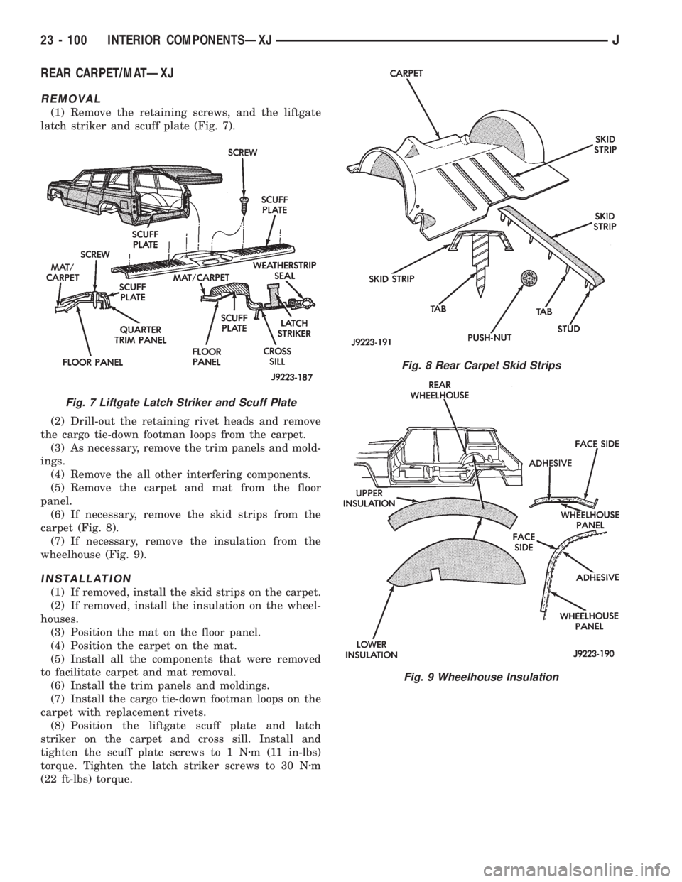
REAR CARPET/MATÐXJ
REMOVAL
(1) Remove the retaining screws, and the liftgate
latch striker and scuff plate (Fig. 7).
(2) Drill-out the retaining rivet heads and remove
the cargo tie-down footman loops from the carpet.
(3) As necessary, remove the trim panels and mold-
ings.
(4) Remove the all other interfering components.
(5) Remove the carpet and mat from the floor
panel.
(6) If necessary, remove the skid strips from the
carpet (Fig. 8).
(7) If necessary, remove the insulation from the
wheelhouse (Fig. 9).
INSTALLATION
(1) If removed, install the skid strips on the carpet.
(2) If removed, install the insulation on the wheel-
houses.
(3) Position the mat on the floor panel.
(4) Position the carpet on the mat.
(5) Install all the components that were removed
to facilitate carpet and mat removal.
(6) Install the trim panels and moldings.
(7) Install the cargo tie-down footman loops on the
carpet with replacement rivets.
(8) Position the liftgate scuff plate and latch
striker on the carpet and cross sill. Install and
tighten the scuff plate screws to 1 Nzm (11 in-lbs)
torque. Tighten the latch striker screws to 30 Nzm
(22 ft-lbs) torque.
Fig. 7 Liftgate Latch Striker and Scuff Plate
Fig. 8 Rear Carpet Skid Strips
Fig. 9 Wheelhouse Insulation
23 - 100 INTERIOR COMPONENTSÐXJJ
Page 1834 of 2198
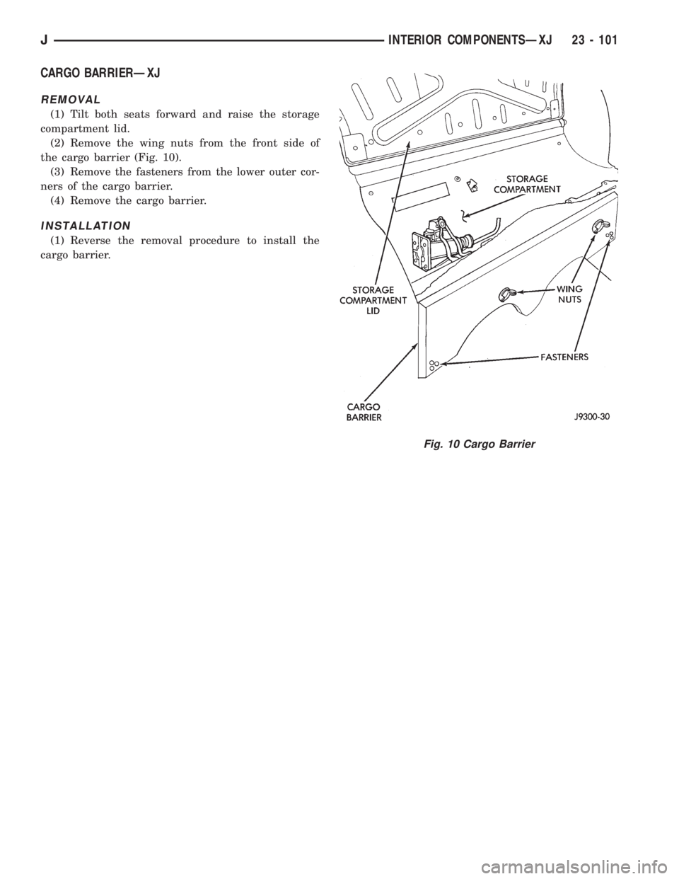
CARGO BARRIERÐXJ
REMOVAL
(1) Tilt both seats forward and raise the storage
compartment lid.
(2) Remove the wing nuts from the front side of
the cargo barrier (Fig. 10).
(3) Remove the fasteners from the lower outer cor-
ners of the cargo barrier.
(4) Remove the cargo barrier.
INSTALLATION
(1) Reverse the removal procedure to install the
cargo barrier.
Fig. 10 Cargo Barrier
JINTERIOR COMPONENTSÐXJ 23 - 101
Page 1835 of 2198
BODY COMPONENTSÐYJ VEHICLES
CONTENTS
page page
DOORS............................... 134
EXTERIOR COMPONENTS................ 104
GENERAL SERVICE INFORMATION......... 102INTERIOR COMPONENTS................ 151
PAINT................................ 158
STATIONARY GLASS.................... 144
GENERAL SERVICE INFORMATION
LABELS/DECALS/PLATESÐYJ
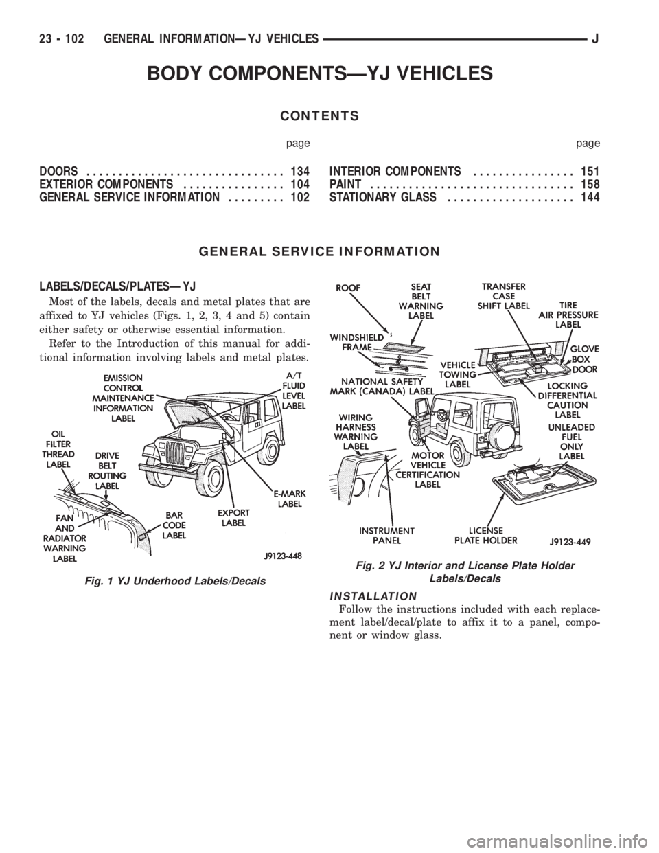
Most of the labels, decals and metal plates that are
affixed to YJ vehicles (Figs. 1, 2, 3, 4 and 5) contain
either safety or otherwise essential information.
Refer to the Introduction of this manual for addi-
tional information involving labels and metal plates.
INSTALLATION
Follow the instructions included with each replace-
ment label/decal/plate to affix it to a panel, compo-
nent or window glass.
Fig. 1 YJ Underhood Labels/Decals
Fig. 2 YJ Interior and License Plate Holder
Labels/Decals
23 - 102 GENERAL INFORMATIONÐYJ VEHICLESJ
Page 1836 of 2198
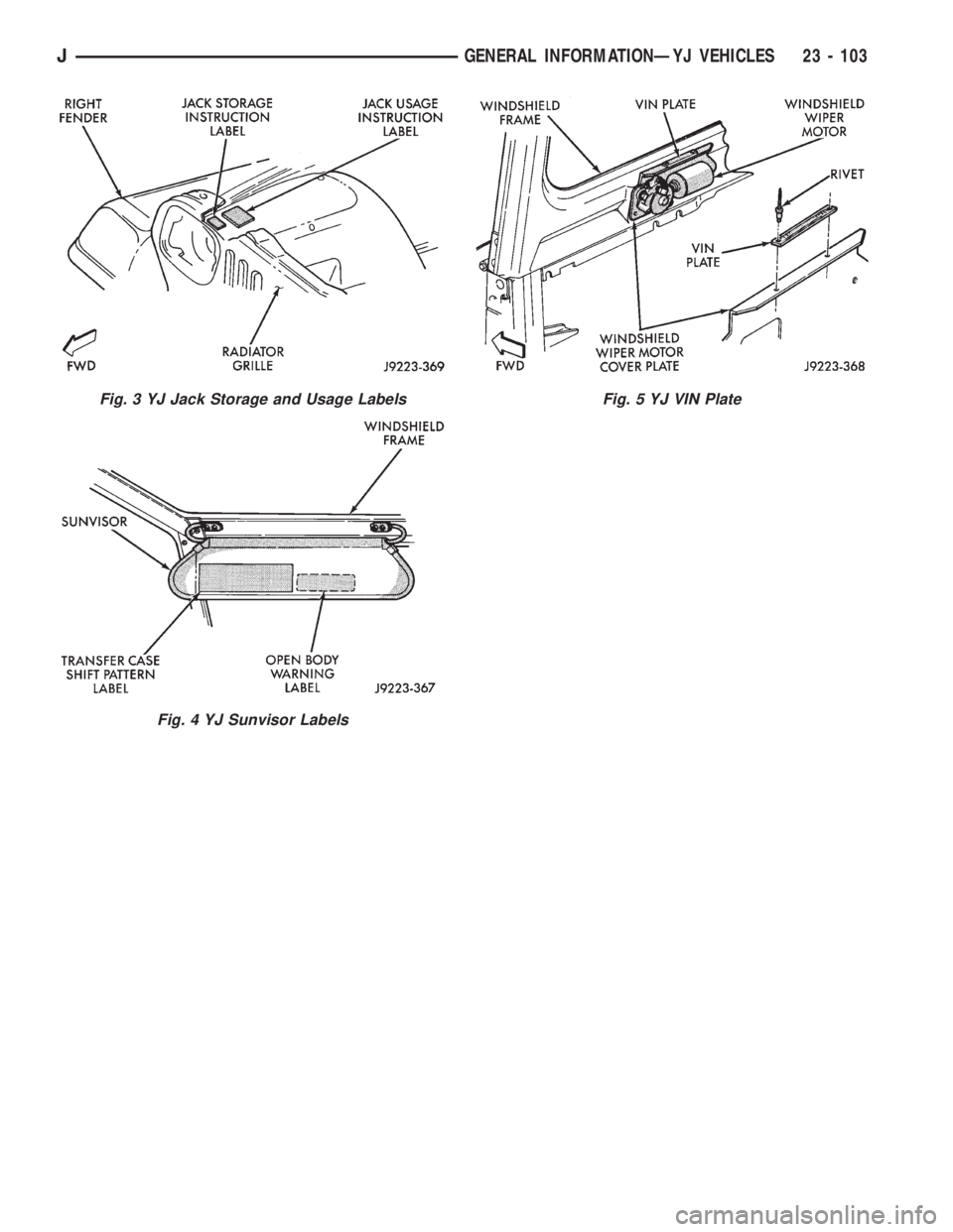
Fig. 3 YJ Jack Storage and Usage Labels
Fig. 4 YJ Sunvisor Labels
Fig. 5 YJ VIN Plate
JGENERAL INFORMATIONÐYJ VEHICLES 23 - 103
Page 1837 of 2198
EXTERIOR COMPONENTS
INDEX
page page
Battery TrayÐYJ......................... 110
Body Side Step MoldingÐYJ................ 115
Body Stripes/DecalsÐYJ................... 116
Cowl Grille and ScreenÐYJ................ 109
Cowl Weatherstrip SealÐYJ................ 109
Exterior Nameplates (Adhesive-Backed)ÐYJ.... 120
External Spare/Wheel Tire CarrierÐYJ........ 133
Fender FlareÐYJ........................ 114
Fender Inner Splash ShieldsÐYJ............. 116
Fender Splash ApronsÐYJ................. 115
FendersÐYJ............................ 110
Fuel Filler Protector/NozzleÐYJ............. 121
Half Metal Door Mirror (External)ÐYJ......... 121
Hard Top Liftgate GlassÐYJ................ 124
Hard Top RepairÐYJ..................... 127
Hard Top Roof VentÐYJ................... 127
Hard TopÐYJ........................... 126Hood AlignmentÐYJ...................... 107
Hood Insulator PanelÐYJ.................. 107
Hood Safety LatchÐYJ.................... 109
HoodÐYJ.............................. 107
Liftgate Glass Weatherstrip Seal ReplacementÐYJ. 125
Radiator Grille AppliqueÐYJ................ 104
Soft Top Service InformationÐYJ............. 127
Soft Top ServiceÐYJ..................... 129
Sport BarÐYJ........................... 132
Tailgate AdjustmentÐYJ................... 121
Tailgate HingeÐYJ....................... 121
Tailgate Latch and Release HandleÐYJ........ 122
Tailgate Latch StrikerÐYJ.................. 123
Tailgate Lock CylinderÐYJ................. 122
Tailgate Weatherstrip SealÐYJ.............. 123
TailgateÐYJ............................ 121
Wheelhouse Splash LinersÐYJ.............. 115
RADIATOR GRILLE APPLIQUEÐYJ
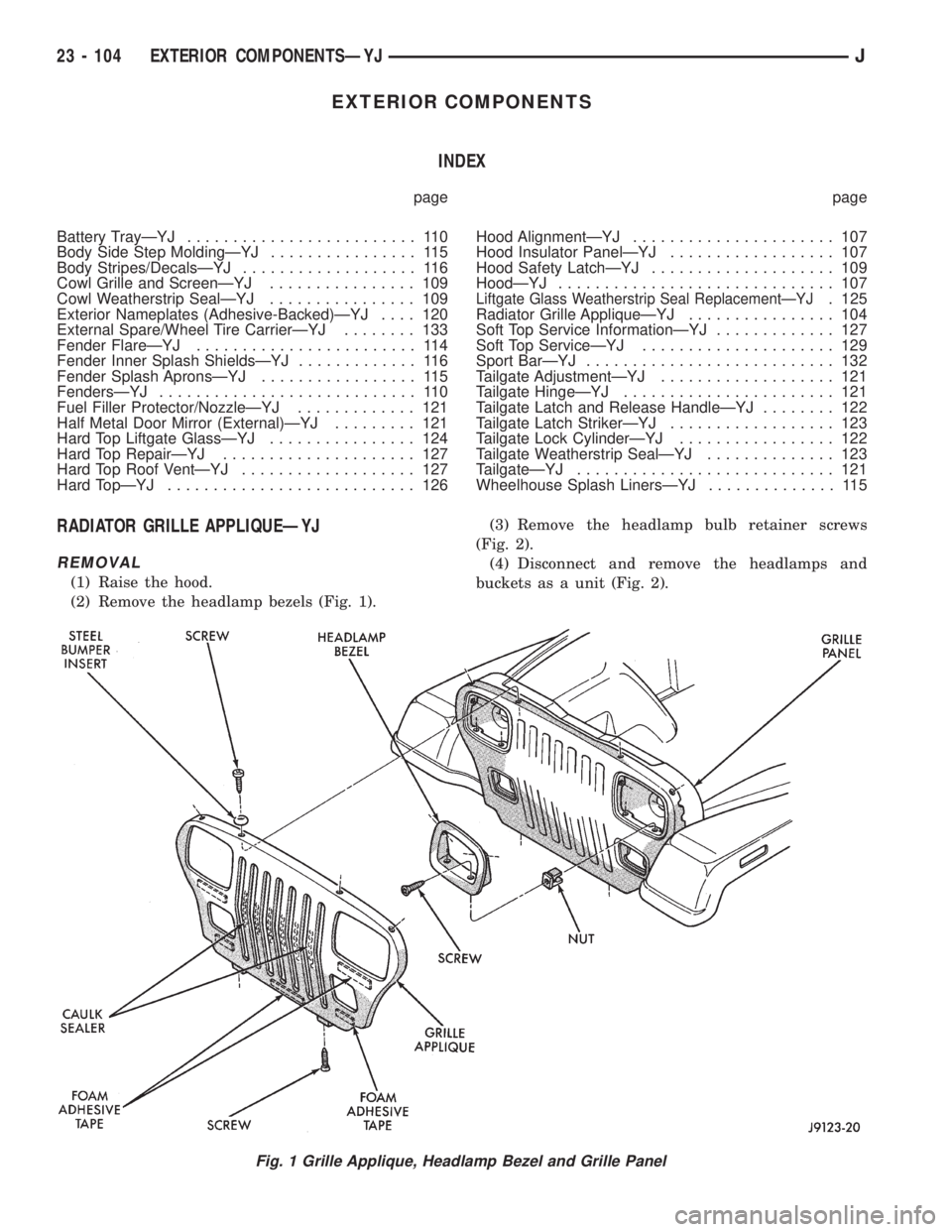
REMOVAL
(1) Raise the hood.
(2) Remove the headlamp bezels (Fig. 1).(3) Remove the headlamp bulb retainer screws
(Fig. 2).
(4) Disconnect and remove the headlamps and
buckets as a unit (Fig. 2).
Fig. 1 Grille Applique, Headlamp Bezel and Grille Panel
23 - 104 EXTERIOR COMPONENTSÐYJJ
Page 1838 of 2198
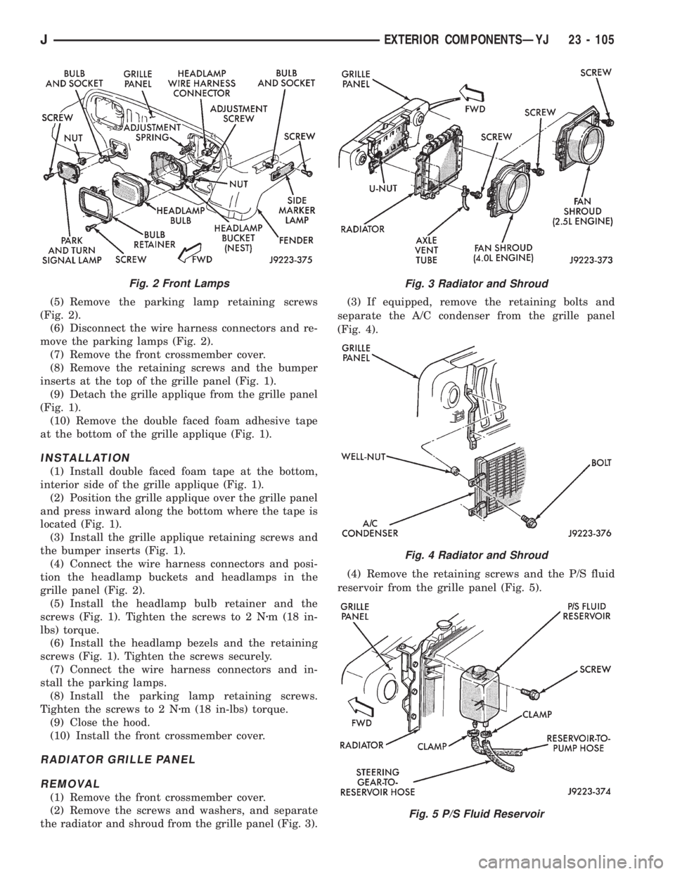
(5) Remove the parking lamp retaining screws
(Fig. 2).
(6) Disconnect the wire harness connectors and re-
move the parking lamps (Fig. 2).
(7) Remove the front crossmember cover.
(8) Remove the retaining screws and the bumper
inserts at the top of the grille panel (Fig. 1).
(9) Detach the grille applique from the grille panel
(Fig. 1).
(10) Remove the double faced foam adhesive tape
at the bottom of the grille applique (Fig. 1).
INSTALLATION
(1) Install double faced foam tape at the bottom,
interior side of the grille applique (Fig. 1).
(2) Position the grille applique over the grille panel
and press inward along the bottom where the tape is
located (Fig. 1).
(3) Install the grille applique retaining screws and
the bumper inserts (Fig. 1).
(4) Connect the wire harness connectors and posi-
tion the headlamp buckets and headlamps in the
grille panel (Fig. 2).
(5) Install the headlamp bulb retainer and the
screws (Fig. 1). Tighten the screws to 2 Nzm (18 in-
lbs) torque.
(6) Install the headlamp bezels and the retaining
screws (Fig. 1). Tighten the screws securely.
(7) Connect the wire harness connectors and in-
stall the parking lamps.
(8) Install the parking lamp retaining screws.
Tighten the screws to 2 Nzm (18 in-lbs) torque.
(9) Close the hood.
(10) Install the front crossmember cover.
RADIATOR GRILLE PANEL
REMOVAL
(1) Remove the front crossmember cover.
(2) Remove the screws and washers, and separate
the radiator and shroud from the grille panel (Fig. 3).(3) If equipped, remove the retaining bolts and
separate the A/C condenser from the grille panel
(Fig. 4).
(4) Remove the retaining screws and the P/S fluid
reservoir from the grille panel (Fig. 5).
Fig. 2 Front LampsFig. 3 Radiator and Shroud
Fig. 4 Radiator and Shroud
Fig. 5 P/S Fluid Reservoir
JEXTERIOR COMPONENTSÐYJ 23 - 105
Page 1839 of 2198
(5) Remove the retaining screws and the air intake
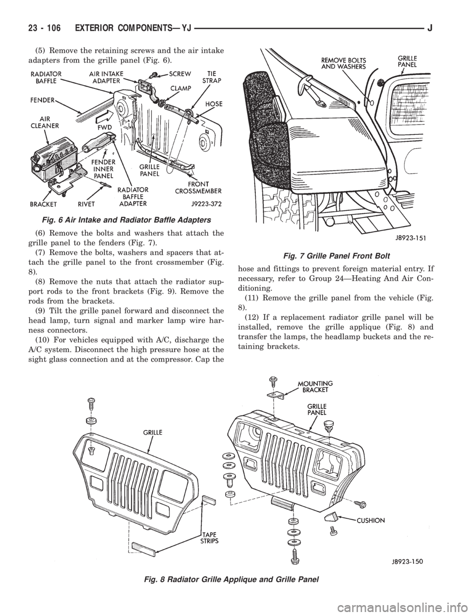
adapters from the grille panel (Fig. 6).
(6) Remove the bolts and washers that attach the
grille panel to the fenders (Fig. 7).
(7) Remove the bolts, washers and spacers that at-
tach the grille panel to the front crossmember (Fig.
8).
(8) Remove the nuts that attach the radiator sup-
port rods to the front brackets (Fig. 9). Remove the
rods from the brackets.
(9) Tilt the grille panel forward and disconnect the
head lamp, turn signal and marker lamp wire har-
ness connectors.
(10) For vehicles equipped with A/C, discharge the
A/C system. Disconnect the high pressure hose at the
sight glass connection and at the compressor. Cap thehose and fittings to prevent foreign material entry. If
necessary, refer to Group 24ÐHeating And Air Con-
ditioning.
(11) Remove the grille panel from the vehicle (Fig.
8).
(12) If a replacement radiator grille panel will be
installed, remove the grille applique (Fig. 8) and
transfer the lamps, the headlamp buckets and the re-
taining brackets.
Fig. 7 Grille Panel Front Bolt
Fig. 8 Radiator Grille Applique and Grille Panel
Fig. 6 Air Intake and Radiator Baffle Adapters
23 - 106 EXTERIOR COMPONENTSÐYJJ
Page 1840 of 2198
INSTALLATION
(1) Position the grille panel on the vehicle.
(2) Connect the marker, park and headlamp wire
harness connectors.
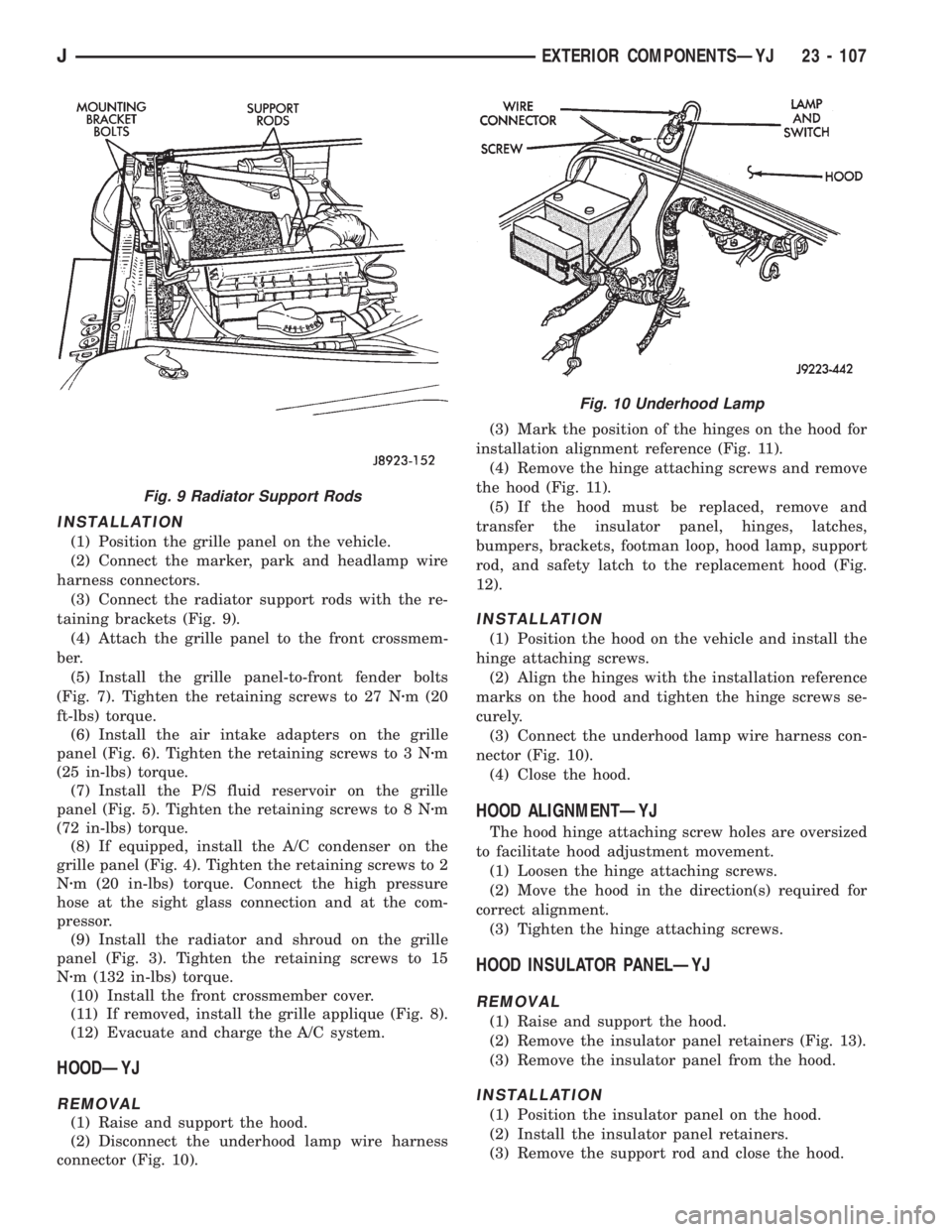
(3) Connect the radiator support rods with the re-
taining brackets (Fig. 9).
(4) Attach the grille panel to the front crossmem-
ber.
(5) Install the grille panel-to-front fender bolts
(Fig. 7). Tighten the retaining screws to 27 Nzm (20
ft-lbs) torque.
(6) Install the air intake adapters on the grille
panel (Fig. 6). Tighten the retaining screws to 3 Nzm
(25 in-lbs) torque.
(7) Install the P/S fluid reservoir on the grille
panel (Fig. 5). Tighten the retaining screws to 8 Nzm
(72 in-lbs) torque.
(8) If equipped, install the A/C condenser on the
grille panel (Fig. 4). Tighten the retaining screws to 2
Nzm (20 in-lbs) torque. Connect the high pressure
hose at the sight glass connection and at the com-
pressor.
(9) Install the radiator and shroud on the grille
panel (Fig. 3). Tighten the retaining screws to 15
Nzm (132 in-lbs) torque.
(10) Install the front crossmember cover.
(11) If removed, install the grille applique (Fig. 8).
(12) Evacuate and charge the A/C system.
HOODÐYJ
REMOVAL
(1) Raise and support the hood.
(2) Disconnect the underhood lamp wire harness
connector (Fig. 10).(3) Mark the position of the hinges on the hood for
installation alignment reference (Fig. 11).
(4) Remove the hinge attaching screws and remove
the hood (Fig. 11).
(5) If the hood must be replaced, remove and
transfer the insulator panel, hinges, latches,
bumpers, brackets, footman loop, hood lamp, support
rod, and safety latch to the replacement hood (Fig.
12).
INSTALLATION
(1) Position the hood on the vehicle and install the
hinge attaching screws.
(2) Align the hinges with the installation reference
marks on the hood and tighten the hinge screws se-
curely.
(3) Connect the underhood lamp wire harness con-
nector (Fig. 10).
(4) Close the hood.
HOOD ALIGNMENTÐYJ
The hood hinge attaching screw holes are oversized
to facilitate hood adjustment movement.
(1) Loosen the hinge attaching screws.
(2) Move the hood in the direction(s) required for
correct alignment.
(3) Tighten the hinge attaching screws.
HOOD INSULATOR PANELÐYJ
REMOVAL
(1) Raise and support the hood.
(2) Remove the insulator panel retainers (Fig. 13).
(3) Remove the insulator panel from the hood.
INSTALLATION
(1) Position the insulator panel on the hood.
(2) Install the insulator panel retainers.
(3) Remove the support rod and close the hood.
Fig. 9 Radiator Support Rods
Fig. 10 Underhood Lamp
JEXTERIOR COMPONENTSÐYJ 23 - 107