JEEP CHEROKEE 1995 Service Repair Manual
Manufacturer: JEEP, Model Year: 1995, Model line: CHEROKEE, Model: JEEP CHEROKEE 1995Pages: 2198, PDF Size: 82.83 MB
Page 1921 of 2198
HEATER CORE
REVIEW WARNINGS AND CAUTIONS IN
THIS GROUP BEFORE PERFORMING THIS
OPERATION.
REMOVAL
(1) Drain the radiator.
(2) Disconnect heater hoses at heater core tubes.
(3) Remove heater/evaporator housing side cover.
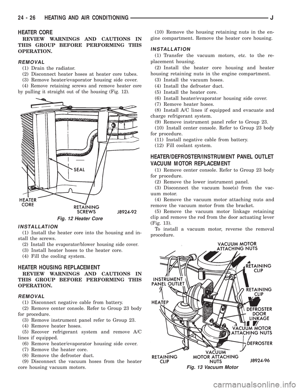
(4) Remove retaining screws and remove heater core
by pulling it straight out of the housing (Fig. 12).
INSTALLATION
(1) Install the heater core into the housing and in-
stall the screws.
(2) Install the evaporator/blower housing side cover.
(3) Install heater hoses to the heater core.
(4) Fill the cooling system.
HEATER HOUSING REPLACEMENT
REVIEW WARNINGS AND CAUTIONS IN
THIS GROUP BEFORE PERFORMING THIS
OPERATION.
REMOVAL
(1) Disconnect negative cable from battery.
(2) Remove center console. Refer to Group 23 body
for procedure.
(3) Remove instrument panel refer to Group 23.
(4) Remove heater hoses.
(5) Recover refrigerant system and remove A/C
lines if equipped.
(6) Remove heater/evaporator housing side cover.
(7) Remove the heater core.
(8) Remove the defroster duct.
(9) Disconnect the vacuum hoses from the heater
core housing vacuum motors.(10) Remove the housing retaining nuts in the en-
gine compartment. Remove the heater core housing.
INSTALLATION
(1) Transfer the vacuum motors, etc. to the re-
placement housing.
(2) Install the heater core housing and heater
housing retaining nuts in the engine compartment.
(3) Install the vacuum hoses.
(4) Install the defroster duct.
(5) Install the heater core.
(6) Install heater/evaporator housing side cover.
(7) Remove heater hoses.
(8) Install A/C lines if equipped and evacuate and
charge refrigerant system.
(9) Remove instrument panel refer to Group 23.
(10) Install center console. Refer to Group 23 body
for procedure.
(11) Install negative cable from battery.
(12) Fill coolant system.
HEATER/DEFROSTER/INSTRUMENT PANEL OUTLET
VACUUM MOTOR REPLACEMENT
(1) Remove center console. Refer to Group 23 body
for procedure.
(2) Remove the lower instrument panel.
(3) Disconnect the vacuum hose(s) from the vac-
uum motor.
(4) Remove the vacuum motor attaching nuts and
remove the vacuum motor from the bracket.
(5) Remove the vacuum motor linkage retaining
clip and remove the rod from the door actuating lever
(Fig. 13).
To install a vacuum motor, reverse the removal
procedure.
Fig. 12 Heater Core
Fig. 13 Vacuum Motor
24 - 26 HEATING AND AIR CONDITIONINGJ
Page 1922 of 2198
A/C RECIRCULATING DOOR VACUUM MOTOR
REPLACEMENT
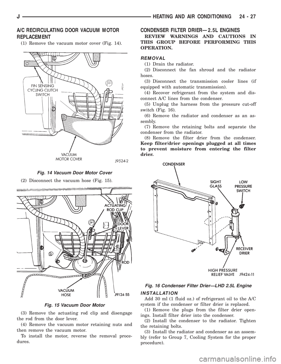
(1) Remove the vacuum motor cover (Fig. 14).
(2) Disconnect the vacuum hose (Fig. 15).
(3) Remove the actuating rod clip and disengage
the rod from the door lever.
(4) Remove the vacuum motor retaining nuts and
then remove the vacuum motor.
To install the motor, reverse the removal proce-
dures.
CONDENSER FILTER DRIERÐ2.5L ENGINES
REVIEW WARNINGS AND CAUTIONS IN
THIS GROUP BEFORE PERFORMING THIS
OPERATION.
REMOVAL
(1) Drain the radiator.
(2) Disconnect the fan shroud and the radiator
hoses.
(3) Disconnect the transmission cooler lines (if
equipped with automatic transmission).
(4) Recover refrigerant from the system and dis-
connect A/C lines from the condenser.
(5) Unplug the harness from the pressure cut-off
switch (Fig. 16).
(6) Remove the radiator and condenser as an as-
sembly.
(7) Remove the retaining bolts and separate the
condenser from the radiator.
(8) Remove the filter drier from the condenser.
Keep filter/drier openings plugged at all times
to prevent moisture from entering the filter
drier.
INSTALLATION
Add 30 ml (1 fluid oz.) of refrigerant oil to the A/C
system if the condenser or filter drier is replaced.
(1) Remove the plugs from the filter drier open-
ings. Install filter drier into the condenser.
(2) Install the condenser to the radiator. Tighten
the retaining bolts.
(3) Install the radiator and condenser as an assem-
bly (refer to Group 7, Cooling System for the proper
procedure).
Fig. 14 Vacuum Door Motor Cover
Fig. 15 Vacuum Door Motor
Fig. 16 Condenser Filter DrierÐLHD 2.5L Engine
JHEATING AND AIR CONDITIONING 24 - 27
Page 1923 of 2198
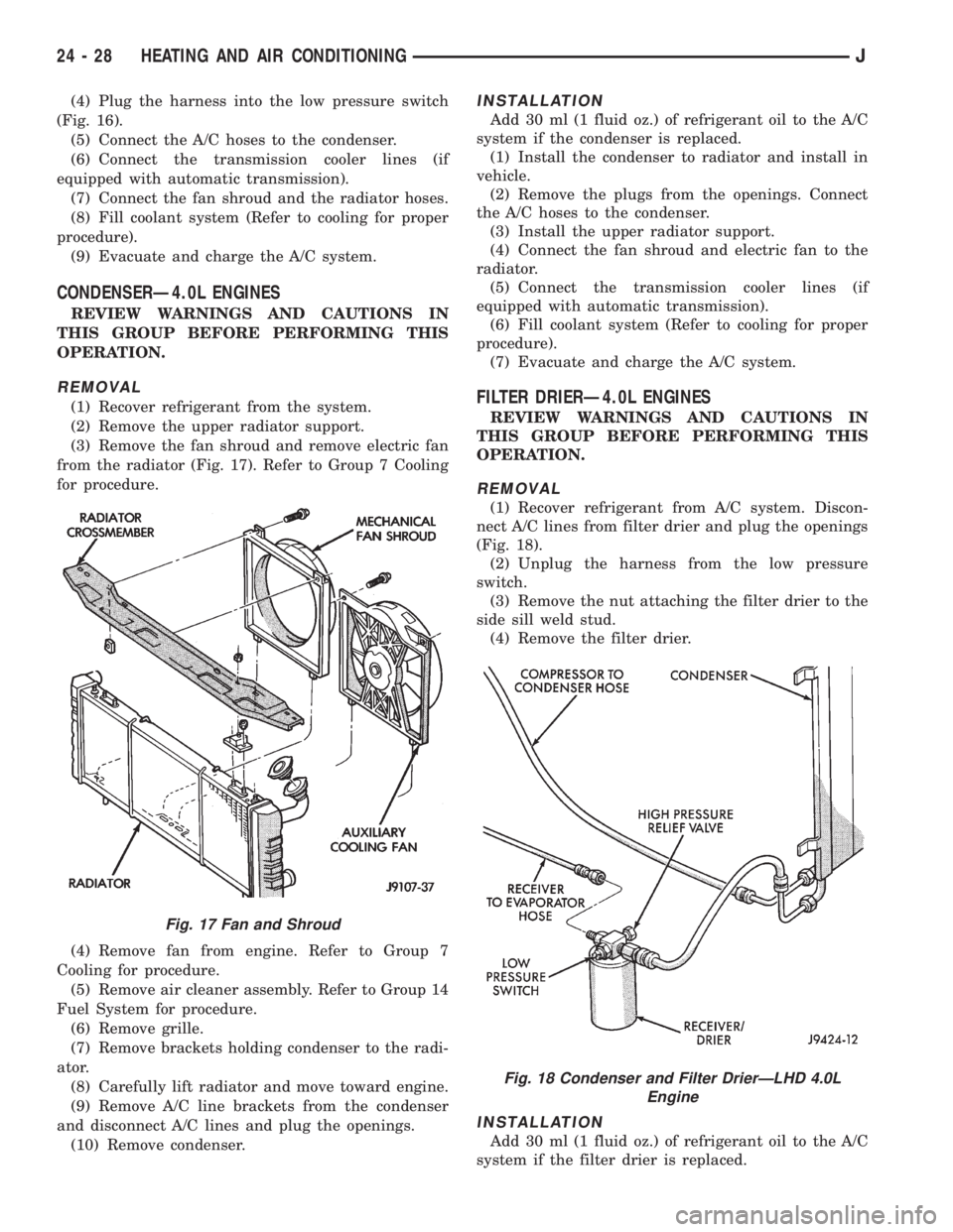
(4) Plug the harness into the low pressure switch
(Fig. 16).
(5) Connect the A/C hoses to the condenser.
(6) Connect the transmission cooler lines (if
equipped with automatic transmission).
(7) Connect the fan shroud and the radiator hoses.
(8) Fill coolant system (Refer to cooling for proper
procedure).
(9) Evacuate and charge the A/C system.
CONDENSERÐ4.0L ENGINES
REVIEW WARNINGS AND CAUTIONS IN
THIS GROUP BEFORE PERFORMING THIS
OPERATION.
REMOVAL
(1) Recover refrigerant from the system.
(2) Remove the upper radiator support.
(3) Remove the fan shroud and remove electric fan
from the radiator (Fig. 17). Refer to Group 7 Cooling
for procedure.
(4) Remove fan from engine. Refer to Group 7
Cooling for procedure.
(5) Remove air cleaner assembly. Refer to Group 14
Fuel System for procedure.
(6) Remove grille.
(7) Remove brackets holding condenser to the radi-
ator.
(8) Carefully lift radiator and move toward engine.
(9) Remove A/C line brackets from the condenser
and disconnect A/C lines and plug the openings.
(10) Remove condenser.
INSTALLATION
Add 30 ml (1 fluid oz.) of refrigerant oil to the A/C
system if the condenser is replaced.
(1) Install the condenser to radiator and install in
vehicle.
(2) Remove the plugs from the openings. Connect
the A/C hoses to the condenser.
(3) Install the upper radiator support.
(4) Connect the fan shroud and electric fan to the
radiator.
(5) Connect the transmission cooler lines (if
equipped with automatic transmission).
(6) Fill coolant system (Refer to cooling for proper
procedure).
(7) Evacuate and charge the A/C system.
FILTER DRIERÐ4.0L ENGINES
REVIEW WARNINGS AND CAUTIONS IN
THIS GROUP BEFORE PERFORMING THIS
OPERATION.
REMOVAL
(1) Recover refrigerant from A/C system. Discon-
nect A/C lines from filter drier and plug the openings
(Fig. 18).
(2) Unplug the harness from the low pressure
switch.
(3) Remove the nut attaching the filter drier to the
side sill weld stud.
(4) Remove the filter drier.
INSTALLATION
Add 30 ml (1 fluid oz.) of refrigerant oil to the A/C
system if the filter drier is replaced.
Fig. 17 Fan and Shroud
Fig. 18 Condenser and Filter DrierÐLHD 4.0L
Engine
24 - 28 HEATING AND AIR CONDITIONINGJ
Page 1924 of 2198
(1) Install the filter drier.
(2) Install and tighten the nut attaching the filter
drier to the side sill weld stud.
(3) Plug the harness to the low pressure switch.
(4) Remove the plugs the openings. Connect the
A/C hoses to the receiver dryer.
(5) Evacuate and charge the A/C system.
EVAPORATOR/BLOWER HOUSING
REVIEW WARNINGS AND CAUTIONS IN
THIS GROUP BEFORE PERFORMING THIS
OPERATION.
REMOVAL
(1) Disconnect negative cable from battery.
(2) Recover refrigerant from A/C system and dis-
connect A/C lines from the expansion valve.
(3) Disconnect the blower motor wires and the vent
tube.
(4) Remove center console. Refer to Group 23 body
for procedure.
(5) Remove the lower instrument panel.
(6) Disconnect the electrical connections at the
blower motor resistors and cycling clutch switch. Dis-
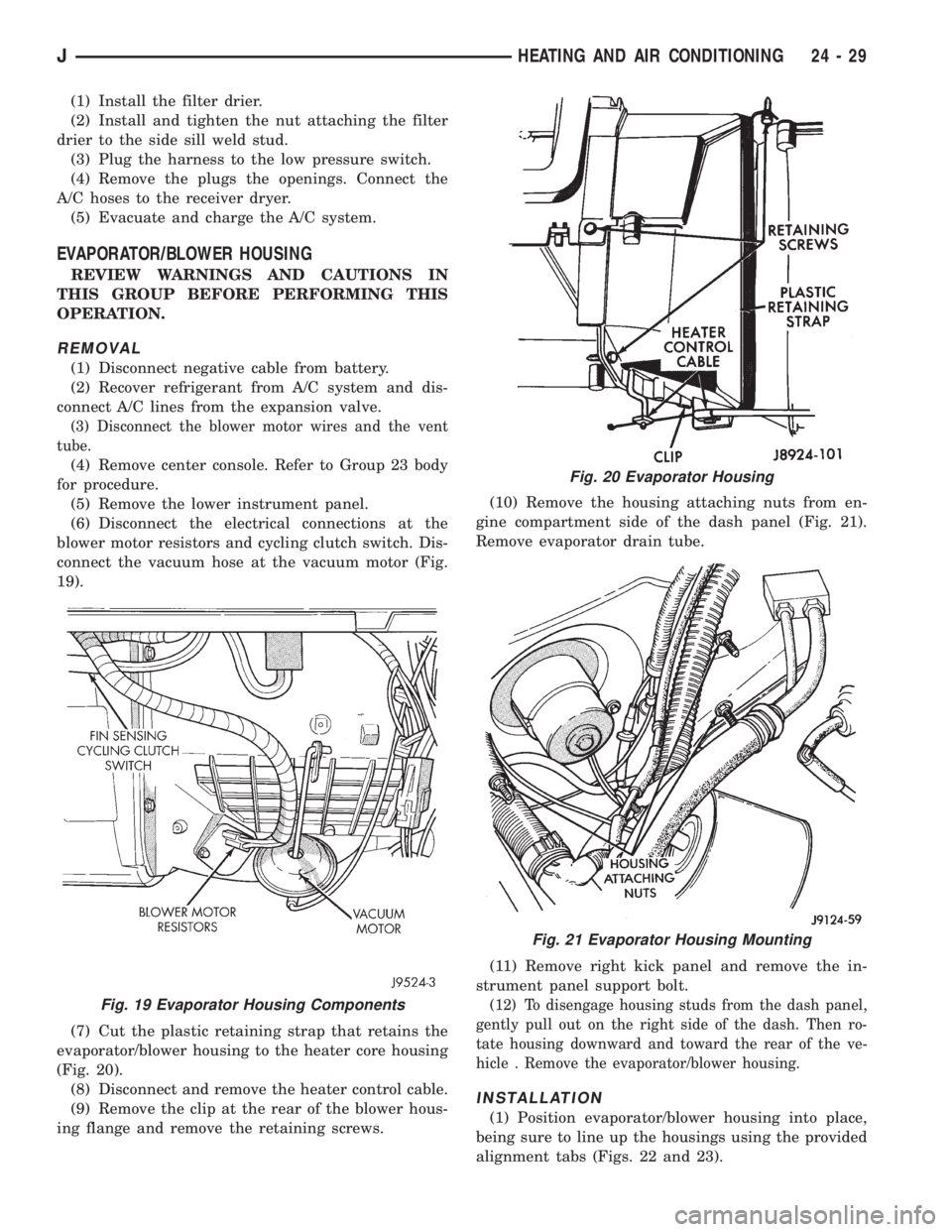
connect the vacuum hose at the vacuum motor (Fig.
19).
(7) Cut the plastic retaining strap that retains the
evaporator/blower housing to the heater core housing
(Fig. 20).
(8) Disconnect and remove the heater control cable.
(9) Remove the clip at the rear of the blower hous-
ing flange and remove the retaining screws.(10) Remove the housing attaching nuts from en-
gine compartment side of the dash panel (Fig. 21).
Remove evaporator drain tube.
(11) Remove right kick panel and remove the in-
strument panel support bolt.
(12) To disengage housing studs from the dash panel,
gently pull out on the right side of the dash. Then ro-
tate housing downward and toward the rear of the ve-
hicle . Remove the evaporator/blower housing.
INSTALLATION
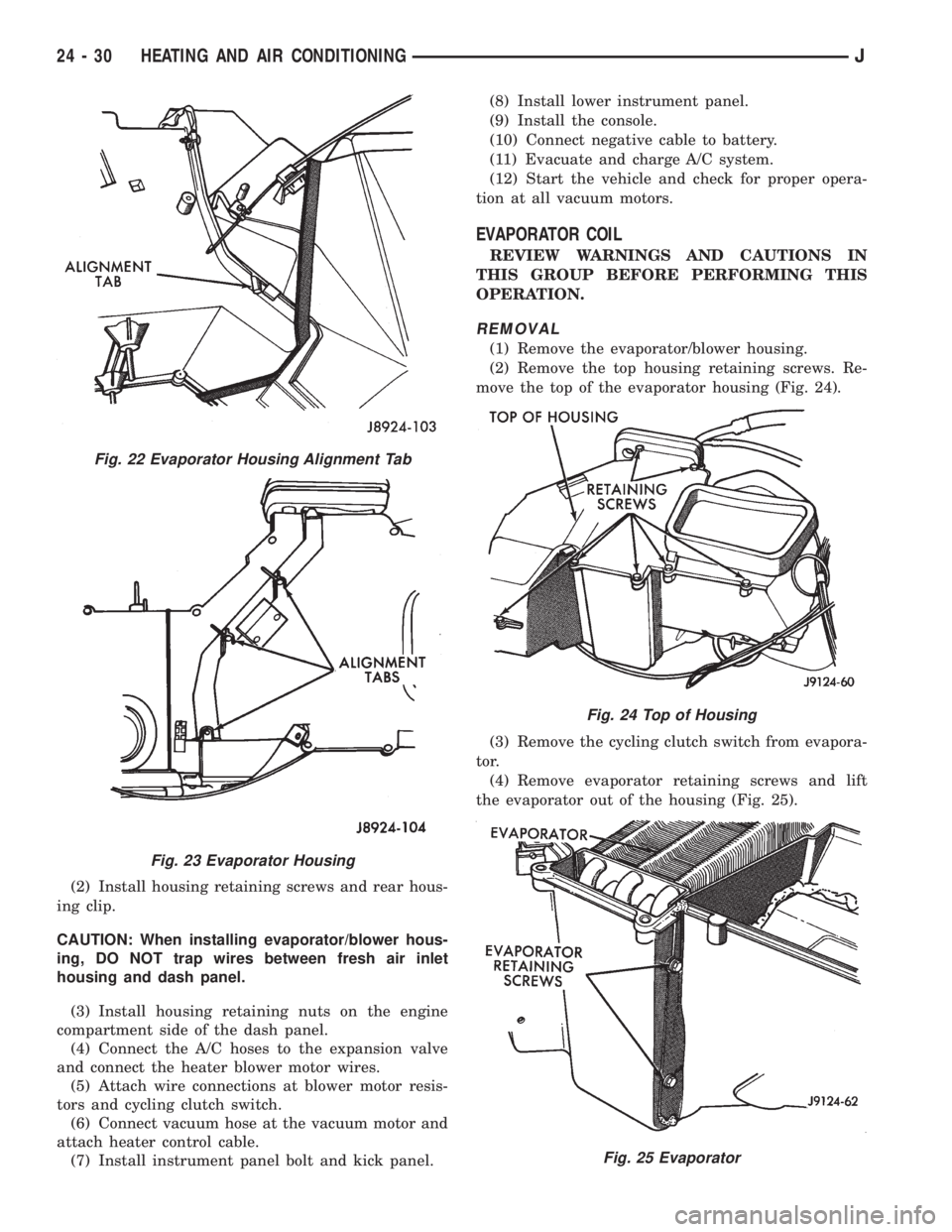
(1) Position evaporator/blower housing into place,
being sure to line up the housings using the provided
alignment tabs (Figs. 22 and 23).
Fig. 19 Evaporator Housing Components
Fig. 20 Evaporator Housing
Fig. 21 Evaporator Housing Mounting
JHEATING AND AIR CONDITIONING 24 - 29
Page 1925 of 2198
(2) Install housing retaining screws and rear hous-
ing clip.
CAUTION: When installing evaporator/blower hous-
ing, DO NOT trap wires between fresh air inlet
housing and dash panel.
(3) Install housing retaining nuts on the engine
compartment side of the dash panel.
(4) Connect the A/C hoses to the expansion valve
and connect the heater blower motor wires.
(5) Attach wire connections at blower motor resis-
tors and cycling clutch switch.
(6) Connect vacuum hose at the vacuum motor and
attach heater control cable.
(7) Install instrument panel bolt and kick panel.(8) Install lower instrument panel.
(9) Install the console.
(10) Connect negative cable to battery.
(11) Evacuate and charge A/C system.
(12) Start the vehicle and check for proper opera-
tion at all vacuum motors.
EVAPORATOR COIL
REVIEW WARNINGS AND CAUTIONS IN
THIS GROUP BEFORE PERFORMING THIS
OPERATION.
REMOVAL
(1) Remove the evaporator/blower housing.
(2) Remove the top housing retaining screws. Re-
move the top of the evaporator housing (Fig. 24).
(3) Remove the cycling clutch switch from evapora-
tor.
(4) Remove evaporator retaining screws and lift
the evaporator out of the housing (Fig. 25).
Fig. 22 Evaporator Housing Alignment Tab
Fig. 23 Evaporator Housing
Fig. 24 Top of Housing
Fig. 25 Evaporator
24 - 30 HEATING AND AIR CONDITIONINGJ
Page 1926 of 2198
(5) Remove expansion valve from the evaporator.
INSTALLATION
Add 30 ml (1 fluid oz.) of refrigerant oil to the A/C
system if the evaporator is replaced.
(1) Install expansion valve on evaporator.
(2) Position evaporator in the housing. Install and
tighten the evaporator retaining screws.
(3) Install cycling clutch switch into evaporator. In-
stall the top of the evaporator housing.
(4) Install the evaporator/blower housing.
(5) Evacuate and charge A/C system as outlined in
this section.
EXPANSION VALVE
REVIEW ALL WARNINGS AND CAUTIONS IN
THIS GROUP BEFORE PERFORMING THIS
OPERATION.
REMOVAL
(1) Recover refrigerant from A/C system.
(2) Remove the coolant bottle and bracket.
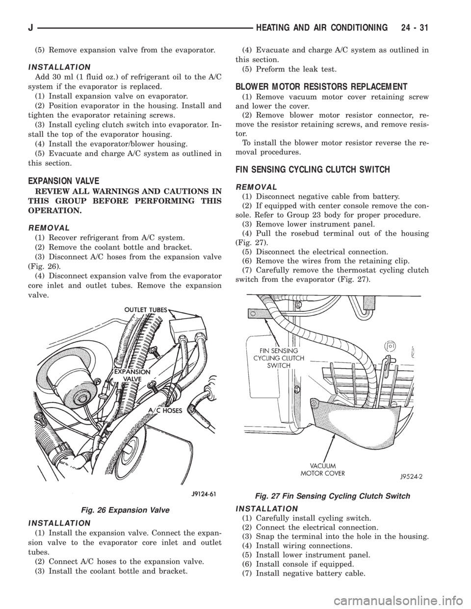
(3) Disconnect A/C hoses from the expansion valve
(Fig. 26).
(4) Disconnect expansion valve from the evaporator
core inlet and outlet tubes. Remove the expansion
valve.
INSTALLATION
(1) Install the expansion valve. Connect the expan-
sion valve to the evaporator core inlet and outlet
tubes.
(2) Connect A/C hoses to the expansion valve.
(3) Install the coolant bottle and bracket.(4) Evacuate and charge A/C system as outlined in
this section.
(5) Preform the leak test.
BLOWER MOTOR RESISTORS REPLACEMENT
(1) Remove vacuum motor cover retaining screw
and lower the cover.
(2) Remove blower motor resistor connector, re-
move the resistor retaining screws, and remove resis-
tor.
To install the blower motor resistor reverse the re-
moval procedures.
FIN SENSING CYCLING CLUTCH SWITCH
REMOVAL
(1) Disconnect negative cable from battery.
(2) If equipped with center console remove the con-
sole. Refer to Group 23 body for proper procedure.
(3) Remove lower instrument panel.
(4) Pull the rosebud terminal out of the housing
(Fig. 27).
(5) Disconnect the electrical connection.
(6) Remove the wires from the retaining clip.
(7) Carefully remove the thermostat cycling clutch
switch from the evaporator (Fig. 27).
INSTALLATION
(1) Carefully install cycling switch.
(2) Connect the electrical connection.
(3) Snap the terminal into the hole in the housing.
(4) Install wiring connections.
(5) Install lower instrument panel.
(6) Install console if equipped.
(7) Install negative battery cable.
Fig. 26 Expansion Valve
Fig. 27 Fin Sensing Cycling Clutch Switch
JHEATING AND AIR CONDITIONING 24 - 31
Page 1927 of 2198
COMPONENT SERVICEÐYJ VEHICLES
INDEX
page page
A/C Blower Motor......................... 35
A/C Condenser........................... 34
Blower Motor (Heating)..................... 33
Blower Motor/Air Door Motor Switch Replacement . 32
Defroster Nozzle and Duct.................. 33
Description.............................. 32
Evaporator and Housing.................... 35
Expansion Valve.......................... 35Fresh Air Door Vacuum Motor................ 34
Fresh Air Intake Duct...................... 34
Heater Control Replacement................. 32
Heater Core and Housing................... 33
Receiver-Drier Replacement................. 35
Temperature Control Thermostat.............. 34
Vent Door Control Cables................... 32
DESCRIPTION
The air conditioning evaporator housing is
mounted to the bottom of instrument panel. The
evaporator, blower motor, thermostat, and expansion
valve are located in the evaporator housing. The com-
pressor, condenser, receiver-dryer and refrigerant
lines are located in the engine compartment.
The heater housing is mounted to the dash panel
behind the instrument panel.
HEATER CONTROL REPLACEMENT
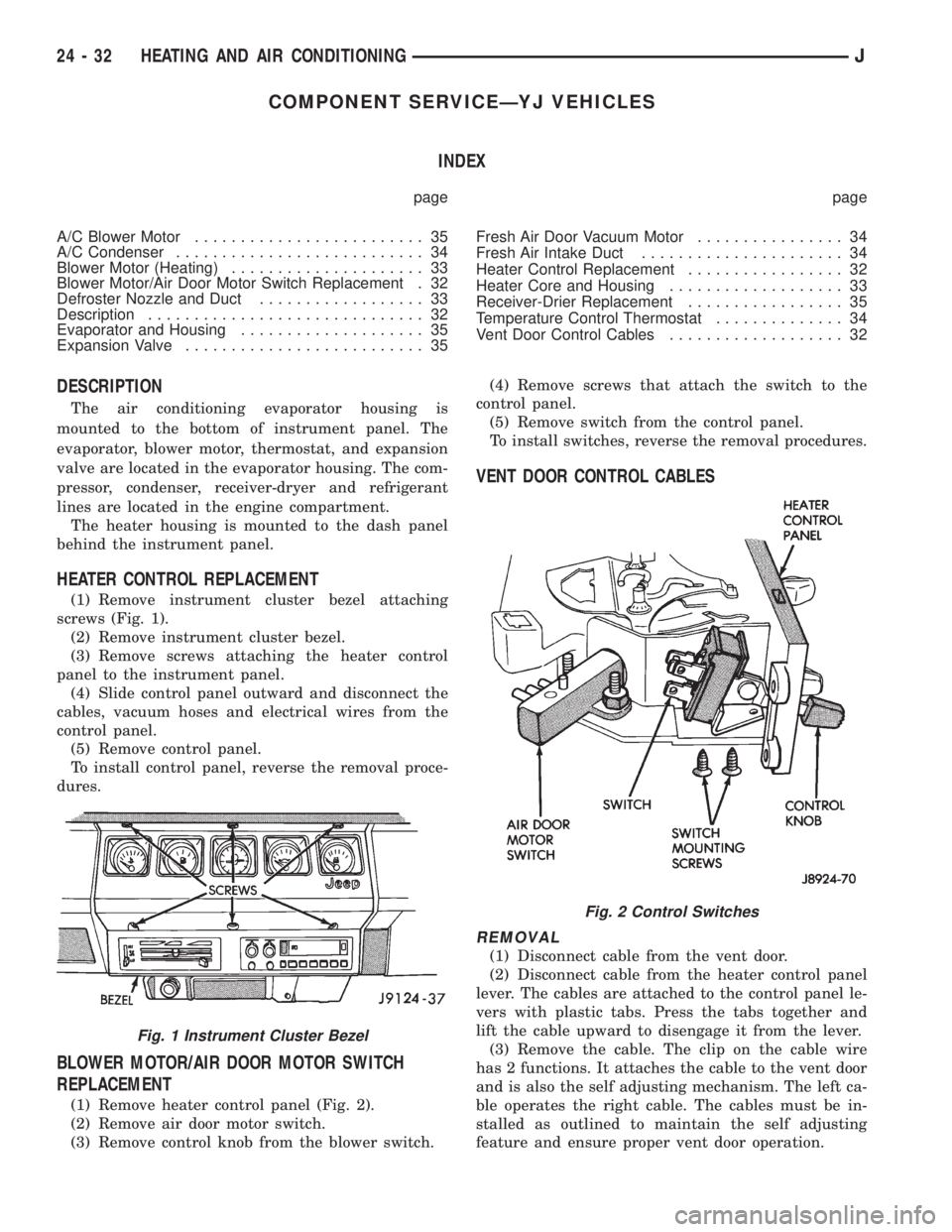
(1) Remove instrument cluster bezel attaching
screws (Fig. 1).
(2) Remove instrument cluster bezel.
(3) Remove screws attaching the heater control
panel to the instrument panel.
(4) Slide control panel outward and disconnect the
cables, vacuum hoses and electrical wires from the
control panel.
(5) Remove control panel.
To install control panel, reverse the removal proce-
dures.
BLOWER MOTOR/AIR DOOR MOTOR SWITCH
REPLACEMENT
(1) Remove heater control panel (Fig. 2).
(2) Remove air door motor switch.
(3) Remove control knob from the blower switch.(4) Remove screws that attach the switch to the
control panel.
(5) Remove switch from the control panel.
To install switches, reverse the removal procedures.
VENT DOOR CONTROL CABLES
REMOVAL
(1) Disconnect cable from the vent door.
(2) Disconnect cable from the heater control panel
lever. The cables are attached to the control panel le-
vers with plastic tabs. Press the tabs together and
lift the cable upward to disengage it from the lever.
(3) Remove the cable. The clip on the cable wire
has 2 functions. It attaches the cable to the vent door
and is also the self adjusting mechanism. The left ca-
ble operates the right cable. The cables must be in-
stalled as outlined to maintain the self adjusting
feature and ensure proper vent door operation.
Fig. 1 Instrument Cluster Bezel
Fig. 2 Control Switches
24 - 32 HEATING AND AIR CONDITIONINGJ
Page 1928 of 2198
INSTALLATION
(1) Install the cables to the heater control panel.
(2) Connect right vent door cable. DO NOT connect
the left door cable at this time.
(3) Open and close the right vent door (one time)
using the air control lever on the heater control
panel.
(4) Connect left vent door cable.
(5) Open and close both vent doors with the air
control lever. Verify that both vent doors open at the
same time.
HEATER CORE AND HOUSING
REVIEW ALL WARNINGS AND CAUTIONS IN
THIS GROUP BEFORE PERFORMING THIS
OPERATION.
REMOVAL
(1) Drain coolant from the radiator.
(2) Disconnect heater hoses.
(3) Disconnect vent door cables.
(4) Disconnect blower motor wire.
(5) Disconnect defroster duct.
(6) Remove nuts that attach the heater housing
studs to the engine compartment side of the dash
panel.
(7) Remove heater housing assembly by tilting it
downward, to disengage it from the defroster duct.
Pull it rearward and out from under the instrument
panel.
(8) Remove heater hosing cover from the housing.
(9) Remove heater core from the housing.
INSTALLATION
(1) Install the heater core into the housing and in-
stall the cover on the housing.
(2) Position heater housing on the dash panel. Be
sure the housing studs all extend through the dash
panel.
(3) Install the seals on the heater core outlet and
inlet tubes and over the blower motor housing.
(4) Install attaching nuts on the housing studs.
CAUTION: DO NOT over tighten the attaching nuts.
The housing could become distorted causing air
leaks and improper heater door operation. Tighten
the nuts alternately and evenly until 2 stud threads
are visible beyond each nut.
(5) Connect defroster duct to the housing.
(6) Connect blower motor wire.
(7) Connect vent door control cables.
(8) Connect heater hoses.
(9) Fill cooling system.
(10) Check system operation.
BLOWER MOTOR (HEATING)
REMOVAL
(1) Remove heater housing.
(2) Remove blower motor-to-heater housing attach-
ing screws/nuts.
(3) Remove blower motor from the housing.
INSTALLATION
(1) Position blower motor into housing.
(2) Install and tighten blower motor-to-heater
housing attaching screws/nuts.
(3) Install heater housing.
(4) Check blower motor and heater operation.
DEFROSTER NOZZLE AND DUCT
REVIEW ALL WARNINGS AND CAUTIONS IN
THIS GROUP BEFORE PERFORMING THIS
OPERATION.
REMOVAL
(1) Drain coolant from the radiator.
(2) Disconnect heater hoses.
(3) Remove nuts attaching the heater housing
studs to the engine compartment side of the dash
panel.
(4) Disconnect speedometer cable.
(5) Remove glove box.
(6) Tilt heater housing back and pull it rearward
and out from under the instrument panel.
(7) Disconnect vent control cables.
(8) Remove fresh air intake grille from the cowl.
(9) Remove fresh air intake duct.
(10) Lower windshield.
(11) Remove defroster nozzle attaching screws and
remove the nozzle and duct.
INSTALLATION
(1) Install defroster nozzle and duct.
(2) Raise and secure the windshield.
(3) Install fresh air intake duct.
(4) Install fresh air intake grille on the cowl.
(5) Install vent cables.
(6) Position heater housing on the dash panel. Be
sure all the housing studs extend through the dash
panel.
(7) Install seals on the blower motor and heater
core inlet and outlet tubes.
(8) Install on the housing studs.
CAUTION: DO NOT over tighten the attaching nuts.
The housing could become distorted causing air
leaks and improper heater door operation. Tighten
the nuts alternately and evenly until 2 stud threads
are visible beyond each nut.
(9) Install glove box.
(10) Connect speedometer cable.
JHEATING AND AIR CONDITIONING 24 - 33
Page 1929 of 2198
(11) Connect the heater hoses.
(12) Fill cooling system.
FRESH AIR DOOR VACUUM MOTOR
REMOVAL
(1) Remove glove box and assist handle.
(2) Disconnect vacuum hose from the motor.
(3) Remove motor lever retaining clip.
(4) Remove motor attaching nuts and remove the
motor from the fresh air duct.
INSTALLATION
(1) Position motor on fresh air duct and install the
motor attaching nuts.
(2) Align motor lever with the air door lever and
install the lever retaining clip.
(3) Connect vacuum hose to the motor.
(4) Install glove box and assist handle.
FRESH AIR INTAKE DUCT
REVIEW WARNINGS AND CAUTIONS IN
THIS GROUP BEFORE PERFORMING THIS
OPERATION.
REMOVAL
(1) Drain coolant from the radiator.
(2) Disconnect heater hoses.
(3) Remove nuts attaching the heater housing
studs to the dash panel from inside the engine com-
partment.
(4) Disconnect speedometer cable.
(5) Remove glove box and assist handle.
(6) Tilt heater housing back and pull it rearward
and out from under the instrument panel.
(7) Disconnect vent cables.
(8) Remove windshield bracket bolts and lower
windshield.
(9) Remove fresh air intake grille from the cowl.
(10) Remove fresh air intake duct.
INSTALLATION
(1) Install fresh air intake duct.
(2) Install defroster nozzle and duct.
(3) Raise and secure the windshield.
(4) Install fresh air grille on the cowl.
(5) Install vent cables.
(6) Position heater housing on the dash panel. Be
sure all the housing studs extend through the dash
panel.
(7) Install seals on the blower motor and heater
core inlet and outlet tubes.
(8) Install nuts on the heater housing studs.
CAUTION: DO NOT over tighten the attaching nuts.
The housing could become distorted causing air
leaks and improper heater door operation. Tightenthe nuts alternately and evenly until 2 stud threads
are visible beyond each nut.
(9) Install glove box and assist handle.
(10) Connect speedometer cable.
(11) Connect heater hoses.
(12) Fill cooling system.
TEMPERATURE CONTROL THERMOSTAT
REMOVAL
(1) Remove mounting bolts and lower the evapora-
tor housing.
(2) Remove the attaching screws holding the top
and bottom housings together.
(3) Separate the housings.
(4) Remove the thermostat.
INSTALLATION
(1) Install temperature control thermostat. Insert
thermostat capillary tube into the evaporator coil a
minimum of 50 mm (2 inch).
CAUTION: Handle the tube with care to avoid bends
or kinks that could cause the thermostat to mal-
function.
(2) Assemble the housing and install the attaching
screws. DO NOT over tighten the attaching screws.
(3) Install the evaporator housing.
A/C CONDENSER
REVIEW WARNINGS AND CAUTIONS IN
THIS GROUP BEFORE PERFORMING THIS
OPERATION.
REMOVAL
(1) Recover refrigerant from A/C system.
(2) Drain the radiator.
(3) Remove fan shroud and radiator.
(4) Disconnect A/C line from the condenser.
(5) Remove condenser attaching screws and tilt the
bottom of the condenser toward the engine.Plug all
the condenser openings to prevent entry of dirt
or moisture.
(6) Working from under the vehicle, disconnect the
receiver-drier to-evaporator hose fitting from the re-
ceiver-drier.
(7) Remove condenser and receiver-drier as an as-
sembly.
(8) Remove receiver-drier from the condenser, if
necessary.
INSTALLATION
Add 30 ml (1 fluid oz.) of refrigerant oil to the A/C
system if the condenser is replaced.
(1) Attach receiver-drier to the condenser.
(2) Install condenser and connect A/C line to the
receiver-drier.
24 - 34 HEATING AND AIR CONDITIONINGJ
Page 1930 of 2198
(3) Install condenser attaching screws.
(4) Connect condenser A/C line.
(5) Install radiator and fan shroud.
(6) Fill coolant system (Refer to cooling for proper
procedure).
(7) Evacuate, charge and leak test the air condi-
tioning system.
RECEIVER-DRIER REPLACEMENT
REVIEW ALL WARNINGS AND CAUTIONS IN
THIS GROUP BEFORE PERFORMING THIS
OPERATION.
REMOVAL
(1) Recover refrigerant from A/C system.
(2) Disconnect A/C lines from the receiver-drier.
(3) Remove receiver-drier attaching screws and re-
move receiver-drier.
INSTALLATION
(1) Position receiver-drier in place and install re-
ceiver-drier attaching screws.
(2) Connect A/C lines to receiver-drier.
(3) Evacuate, charge and leak test the air condi-
tioning system.
EVAPORATOR AND HOUSING
REVIEW ALL WARNINGS AND CAUTIONS IN
THIS GROUP BEFORE PERFORMING THIS
OPERATION.
REMOVAL
(1) Recover refrigerant from A/C system.
(2) Disconnect A/C lines.
(3) Remove hose clamps and dash grommet retain-
ing screws.
(4) Remove the evaporator housing-to-instrument
panel attaching screws and the housing mounting
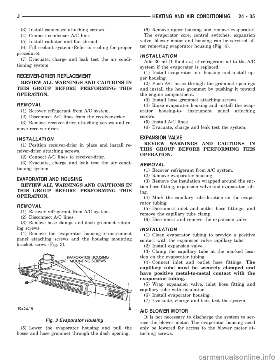
bracket screw (Fig. 3).
(5) Lower the evaporator housing and pull the
hoses and hose grommet through the dash opening.(6) Remove upper housing and remove evaporator.
The evaporator core, control switches, expansion
valve, blower motor and housing can be serviced af-
ter removing evaporator housing (Fig. 4).
INSTALLATION
Add 30 ml (1 fluid oz.) of refrigerant oil to the A/C
system if the evaporator is replaced.
(1) Install evaporator into housing and install up-
per housing.
(2) Push A/C hoses through the grommet openings
and install the hose grommet by pushing it toward
the engine compartment.
(3) Install hose grommet attaching screws.
(4) Raise evaporator housing and install the evap-
orator housing-to- instrument panel attaching
screws.
(5) Install A/C lines.
(6) Evacuate, charge and leak test the system.
EXPANSION VALVE
REVIEW WARNINGS AND CAUTIONS IN
THIS GROUP BEFORE PERFORMING THIS
OPERATION.
REMOVAL
(1) Recover refrigerant from A/C system.
(2) Remove evaporator housing
(3) Remove the insulation wrapped around the suc-
tion hose fitting, expansion valve and evaporator tub-
ing.
(4) Mark the capillary tube location on the evapo-
rator tubing.
(5) Disconnect inlet and outlet hose fittings, and
remove the capillary tube clamp.
(6) Disconnect and remove the expansion valve.
INSTALLATION
(1) Clean evaporator tubing to provide a positive
contact with the expansion valve capillary tube.
(2) Install expansion valve.
(3) Clamp the capillary tube at the marked loca-
tion on the evaporator tubing.
(4) Connect inlet and outlet hose fittings.The
capillary tube must be securely clamped and
have positive metal-to-metal contact with the
evaporator tubing.
(5) Wrap expansion valve, inlet hose fitting and
capillary tube with insulation.
(6) Install evaporator housing.
(7) Evacuate, charge and leak test the system.
A/C BLOWER MOTOR
It is not necessary to discharge the system to ser-
vice the blower motor. The evaporator housing need
only be lowered for access to the blower motor at-
taching screws.Fig. 3 Evaporator Housing
JHEATING AND AIR CONDITIONING 24 - 35