JEEP CHEROKEE 1995 Service Repair Manual
Manufacturer: JEEP, Model Year: 1995, Model line: CHEROKEE, Model: JEEP CHEROKEE 1995Pages: 2198, PDF Size: 82.83 MB
Page 291 of 2198
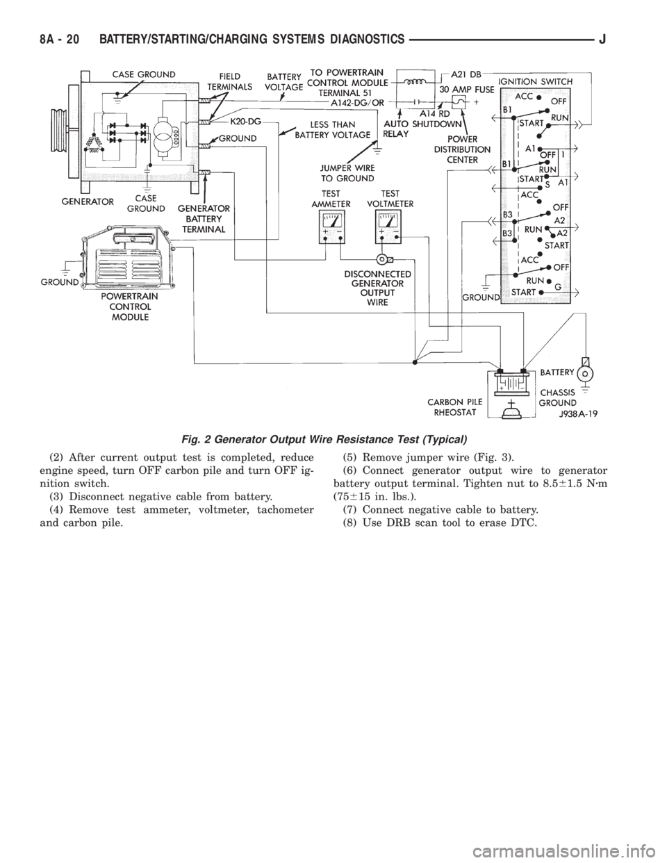
(2) After current output test is completed, reduce
engine speed, turn OFF carbon pile and turn OFF ig-
nition switch.
(3) Disconnect negative cable from battery.
(4) Remove test ammeter, voltmeter, tachometer
and carbon pile.(5) Remove jumper wire (Fig. 3).
(6) Connect generator output wire to generator
battery output terminal. Tighten nut to 8.561.5 Nzm
(75615 in. lbs.).
(7) Connect negative cable to battery.
(8) Use DRB scan tool to erase DTC.
Fig. 2 Generator Output Wire Resistance Test (Typical)
8A - 20 BATTERY/STARTING/CHARGING SYSTEMS DIAGNOSTICSJ
Page 292 of 2198
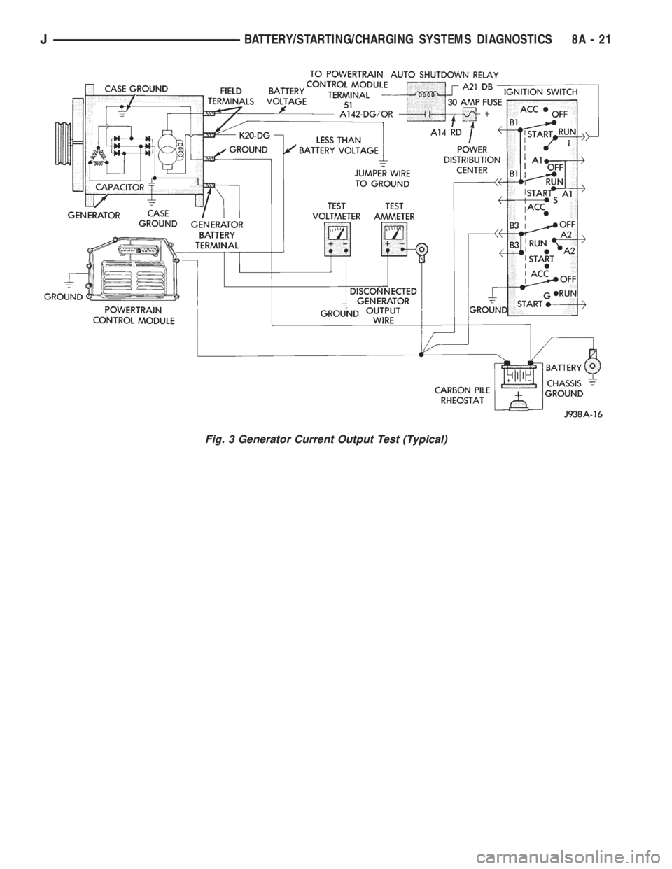
Fig. 3 Generator Current Output Test (Typical)
JBATTERY/STARTING/CHARGING SYSTEMS DIAGNOSTICS 8A - 21
Page 293 of 2198
USING ON-BOARD DIAGNOSTIC SYSTEM
GENERAL INFORMATION
The Powertrain Control Module (PCM) monitors
critical input and output circuits of the charging sys-
tem, making sure they are operational. A Diagnostic
Trouble Code (DTC) is assigned to each input and
output circuit monitored by the OBD system. Some
circuits are checked continuously and some are
checked only under certain conditions.
If the OBD system senses that a monitored circuit
is bad, it will put a DTC into electronic memory. The
DTC will stay in electronic memory as long as the
circuit continues to be bad. The PCM is programmed
to clear the memory after 50 engine starts, if the
problem does not occur again.
DIAGNOSTIC TROUBLE CODES
Diagnostic Trouble Codes (DTC) are two-digit num-
bers flashed on the malfunction indicator (Check En-
gine) lamp that identify which circuit is bad. A DTC
description can also be read using the DRB scan tool.
Refer to Group 14 - Fuel Systems for more informa-
tion.
A DTC does not identify which component in a cir-
cuit is bad. Thus, a DTC should be treated as a
symptom, not as the cause for the problem. In some
cases, because of the design of the diagnostic test
procedure, a DTC can be the reason for another DTCto be set. Therefore, it is important that the test pro-
cedures be followed in sequence, to understand what
caused a DTC to be set.
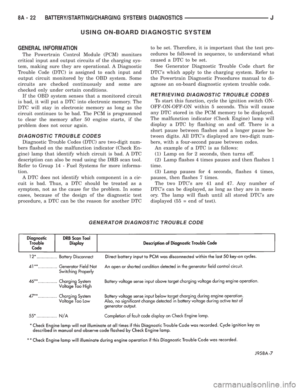
See Generator Diagnostic Trouble Code chart for
DTC's which apply to the charging system. Refer to
the Powertrain Diagnostic Procedures manual to di-
agnose an on-board diagnostic system trouble code.
RETRIEVING DIAGNOSTIC TROUBLE CODES
To start this function, cycle the ignition switch ON-
OFF-ON-OFF-ON within 5 seconds. This will cause
any DTC stored in the PCM memory to be displayed.
The malfunction indicator (Check Engine) lamp will
display a DTC by flashing on and off. There is a
short pause between flashes and a longer pause be-
tween digits. All DTC's displayed are two-digit num-
bers, with a four-second pause between codes.
An example of a DTC is as follows:
(1) Lamp on for 2 seconds, then turns off.
(2) Lamp flashes 4 times pauses and then flashes 1
time.
(3) Lamp pauses for 4 seconds, flashes 4 times,
pauses, then flashes 7 times.
The two DTC's are 41 and 47. Any number of
DTC's can be displayed, as long as they are in mem-
ory. The lamp will flash until all stored DTC's are
displayed (55 = end of test).
GENERATOR DIAGNOSTIC TROUBLE CODE
8A - 22 BATTERY/STARTING/CHARGING SYSTEMS DIAGNOSTICSJ
Page 294 of 2198
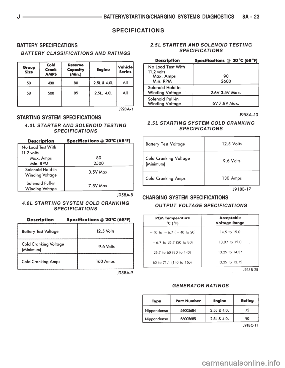
SPECIFICATIONS
BATTERY SPECIFICATIONS
STARTING SYSTEM SPECIFICATIONS
CHARGING SYSTEM SPECIFICATIONS
2.5L STARTER AND SOLENOID TESTING
SPECIFICATIONS
GENERATOR RATINGS
BATTERY CLASSIFICATIONS AND RATINGS
4.0L STARTER AND SOLENOID TESTING
SPECIFICATIONS
4.0L STARTING SYSTEM COLD CRANKING
SPECIFICATIONS
2.5L STARTING SYSTEM COLD CRANKING
SPECIFICATIONS
OUTPUT VOLTAGE SPECIFICATIONS
JBATTERY/STARTING/CHARGING SYSTEMS DIAGNOSTICS 8A - 23
Page 295 of 2198

Page 296 of 2198
BATTERY/STARTER/GENERATOR SERVICE
CONTENTS
page page
BATTERY............................... 1
GENERATOR............................ 6SPECIFICATIONS......................... 8
STARTER AND STARTER RELAY............. 4
GENERAL INFORMATION
Group 8B covers battery, starter and generator ser-
vice procedures. For diagnosis of these components
and their related systems, refer to Group 8A - Bat-tery/Starting/Charging Systems Diagnostics. Refer to
Group 8W - Wiring Diagrams for complete circuit de-
scriptions and diagrams.
BATTERY
GENERAL INFORMATION
This section covers battery service procedures only.
For battery maintenance procedures, refer to Group 0
- Lubrication and Maintenance. While battery charg-
ing can be considered a service or maintenance pro-
cedure, this information is located in Group 8A -
Battery/Starting/Charging Systems Diagnostics. This
was done because the battery must be fully charged
before any diagnosis is performed.
It is important that the battery, starting, and
charging systems be thoroughly tested and inspected
any time a battery needs to be charged or replaced.
The cause of abnormal discharge, over-charging, or
premature failure of the battery must be diagnosed
and corrected before a battery is replaced or returned
to service. Refer to Group 8A - Battery/Starting/
Charging Systems Diagnostics.
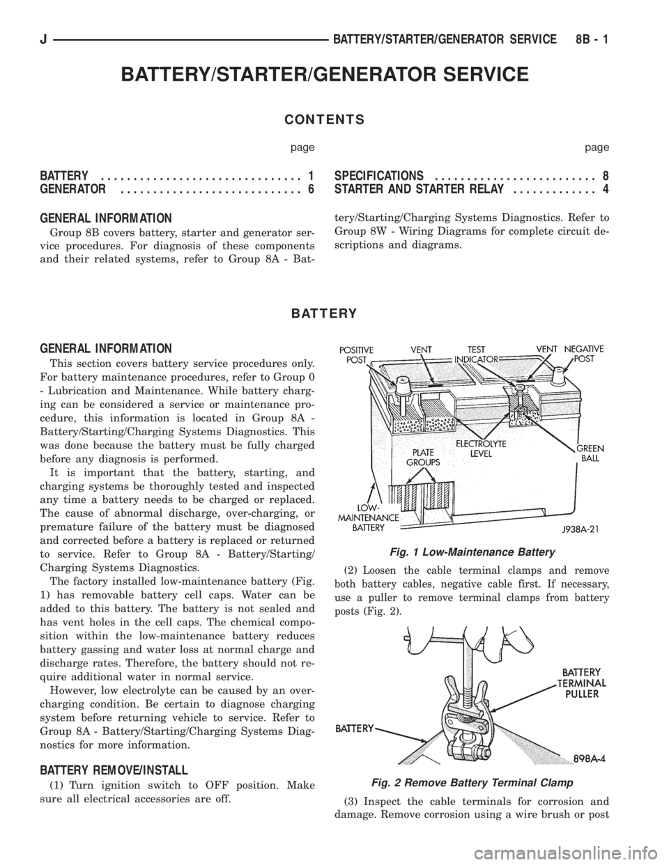
The factory installed low-maintenance battery (Fig.
1) has removable battery cell caps. Water can be
added to this battery. The battery is not sealed and
has vent holes in the cell caps. The chemical compo-
sition within the low-maintenance battery reduces
battery gassing and water loss at normal charge and
discharge rates. Therefore, the battery should not re-
quire additional water in normal service.
However, low electrolyte can be caused by an over-
charging condition. Be certain to diagnose charging
system before returning vehicle to service. Refer to
Group 8A - Battery/Starting/Charging Systems Diag-
nostics for more information.
BATTERY REMOVE/INSTALL
(1) Turn ignition switch to OFF position. Make
sure all electrical accessories are off.
(2) Loosen the cable terminal clamps and remove
both battery cables, negative cable first. If necessary,
use a puller to remove terminal clamps from battery
posts (Fig. 2).
(3) Inspect the cable terminals for corrosion and
damage. Remove corrosion using a wire brush or post
Fig. 1 Low-Maintenance Battery
Fig. 2 Remove Battery Terminal Clamp
JBATTERY/STARTER/GENERATOR SERVICE 8B - 1
Page 297 of 2198
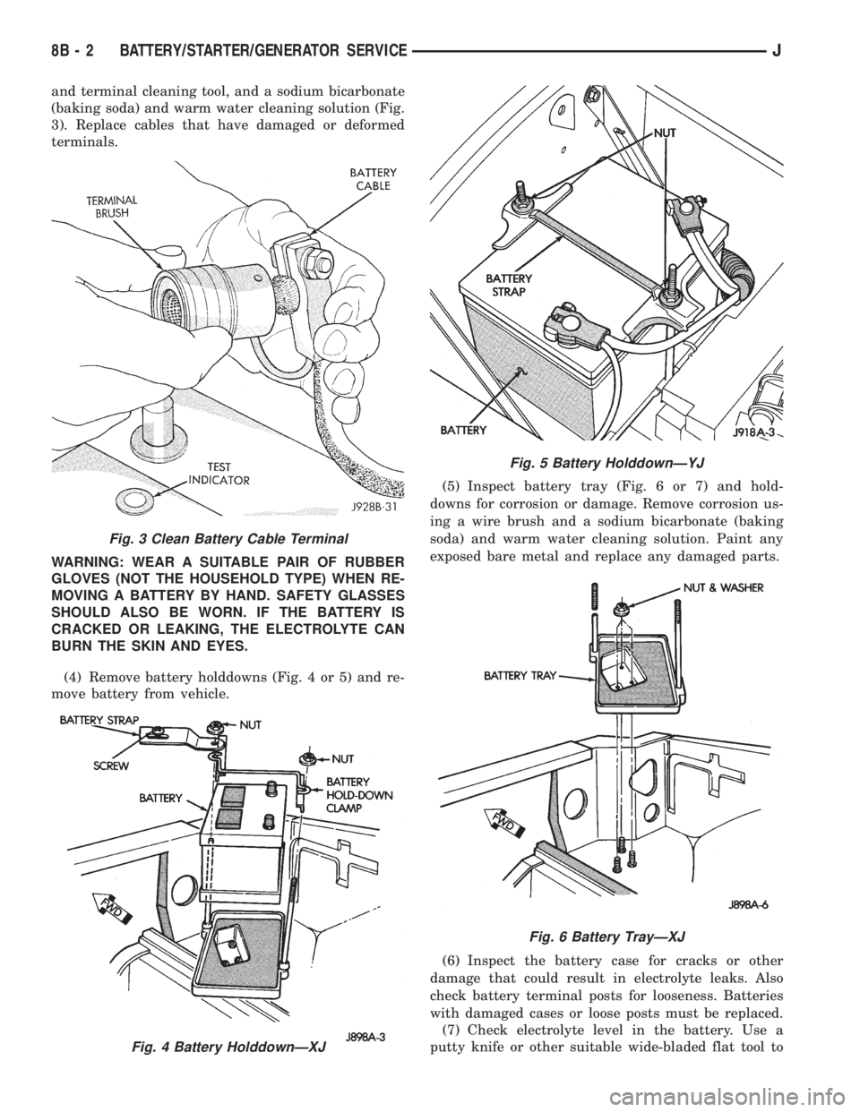
and terminal cleaning tool, and a sodium bicarbonate
(baking soda) and warm water cleaning solution (Fig.
3). Replace cables that have damaged or deformed
terminals.
WARNING: WEAR A SUITABLE PAIR OF RUBBER
GLOVES (NOT THE HOUSEHOLD TYPE) WHEN RE-
MOVING A BATTERY BY HAND. SAFETY GLASSES
SHOULD ALSO BE WORN. IF THE BATTERY IS
CRACKED OR LEAKING, THE ELECTROLYTE CAN
BURN THE SKIN AND EYES.
(4) Remove battery holddowns (Fig. 4 or 5) and re-
move battery from vehicle.(5) Inspect battery tray (Fig. 6 or 7) and hold-
downs for corrosion or damage. Remove corrosion us-
ing a wire brush and a sodium bicarbonate (baking
soda) and warm water cleaning solution. Paint any
exposed bare metal and replace any damaged parts.
(6) Inspect the battery case for cracks or other
damage that could result in electrolyte leaks. Also
check battery terminal posts for looseness. Batteries
with damaged cases or loose posts must be replaced.
(7) Check electrolyte level in the battery. Use a
putty knife or other suitable wide-bladed flat tool to
Fig. 3 Clean Battery Cable Terminal
Fig. 4 Battery HolddownÐXJ
Fig. 5 Battery HolddownÐYJ
Fig. 6 Battery TrayÐXJ
8B - 2 BATTERY/STARTER/GENERATOR SERVICEJ
Page 298 of 2198
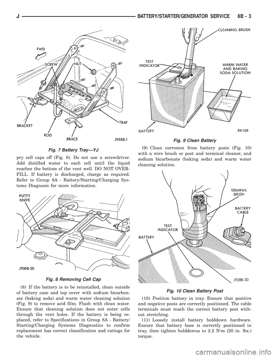
pry cell caps off (Fig. 8). Do not use a screwdriver.
Add distilled water to each cell until the liquid
reaches the bottom of the vent well. DO NOT OVER-
FILL. If battery is discharged, charge as required.
Refer to Group 8A - Battery/Starting/Charging Sys-
tems Diagnosis for more information.
(8) If the battery is to be reinstalled, clean outside
of battery case and top cover with sodium bicarbon-
ate (baking soda) and warm water cleaning solution
(Fig. 9) to remove acid film. Flush with clean water.
Ensure that cleaning solution does not enter cells
through the vent holes. If the battery is being re-
placed, refer to Specifications in Group 8A - Battery/
Starting/Charging Systems Diagnostics to confirm
replacement has correct classification and ratings for
the vehicle.(9) Clean corrosion from battery posts (Fig. 10)
with a wire brush or post and terminal cleaner, and
sodium bicarbonate (baking soda) and warm water
cleaning solution.
(10) Position battery in tray. Ensure that positive
and negative posts are correctly positioned. The cable
terminals must reach the correct battery post with-
out stretching.
(11) Loosely install battery holddown hardware.
Ensure that battery base is correctly positioned in
tray, then tighten holddowns to 2.2 Nzm (20 in. lbs.)
torque.
Fig. 7 Battery TrayÐYJ
Fig. 8 Removing Cell Cap
Fig. 9 Clean Battery
Fig. 10 Clean Battery Post
JBATTERY/STARTER/GENERATOR SERVICE 8B - 3
Page 299 of 2198
CAUTION: Be certain that battery cables are con-
nected to the correct battery terminals. Reverse po-
larity can damage electrical components.
(12) Place oiled felt washer on battery positive ter-
minal post.
(13) Install and tighten battery positive cable ter-
minal clamp. Then install and tighten negative cableterminal clamp. Both cable clamp bolts require
torque of 8.5 Nzm (75 in. lbs.).
(14) Apply a thin coating of petroleum jelly or
chassis grease to cable terminals and battery posts.
STARTER AND STARTER RELAY
GENERAL INFORMATION
This section covers starter and starter relay service
procedures only. For diagnostic procedures, refer to
Group 8A - Battery/Starting/Charging Systems Diag-
nostics. Service procedures for other starting system
components can be found as follows:
²battery - see Battery, in this group
²ignition switch - refer to Group 8D - Ignition Sys-
tems
²park/neutral position switch (automatic transmis-
sion) - refer to Group 21 - Transmission and Transfer
Case
²wiring harness and connectors - refer to Group 8W
- Wiring Diagrams.
STARTER
The starter motor incorporates several features to
create a reliable, efficient, compact and lightweight
unit. A planetary gear system (intermediate trans-
mission) is used between the electric motor and pin-
ion gear. This feature makes it possible to reduce the
dimensions of the starter. At the same time, it allows
higher armature rotational speed and delivers in-
creased torque through the pinion gear to the fly-
wheel or drive plate ring gear.
The use of a permanent magnet field also reduces
starter size and weight. This field consists of six
high-strength permanent magnets. The magnets are
aligned according to their polarity and are perma-
nently fixed in the starter field frame.
The starter motors for all engines are activated by
a solenoid mounted to the overrunning clutch hous-
ing. However, the starter motor/solenoid are serviced
only as a complete assembly. If either component
fails, the entire assembly must be replaced.
This unit is highly sensitive to hammering, shocks
and external pressure.
CAUTION: The starter motor MUST NOT BE
CLAMPED in a vise by the starter field frame. Doing
so may damage the magnets. It may be clamped by
the mounting flange ONLY.CAUTION: Do not connect starter motor incorrectly
when tests are being performed. The permanent
magnets may be damaged and rendered unservice-
able.
STARTER RELAY
The starter relay is an International Standards Or-
ganization (ISO) type relay, and is located in the
Power Distribution Center (PDC). Refer to underside
of PDC cover for relay location.
STARTER REMOVE/INSTALLÐ2.5L
XJ MODELS
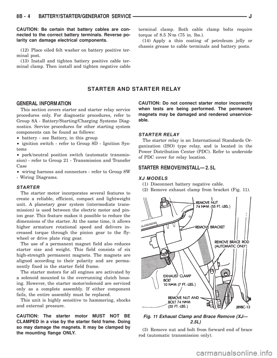
(1) Disconnect battery negative cable.
(2) Remove exhaust clamp from bracket (Fig. 11).
(3) Remove nut and bolt from forward end of brace
rod (automatic transmission only).
Fig. 11 Exhaust Clamp and Brace Remove (XJÐ
2.5L)
8B - 4 BATTERY/STARTER/GENERATOR SERVICEJ
Page 300 of 2198
(4) Remove nut from lower end of brace rod (auto-
matic transmission only).
(5) Remove brace rod and bracket (automatic
transmission only).
(6) Remove nut, bolt and bracket from bell housing
(manual transmission only).
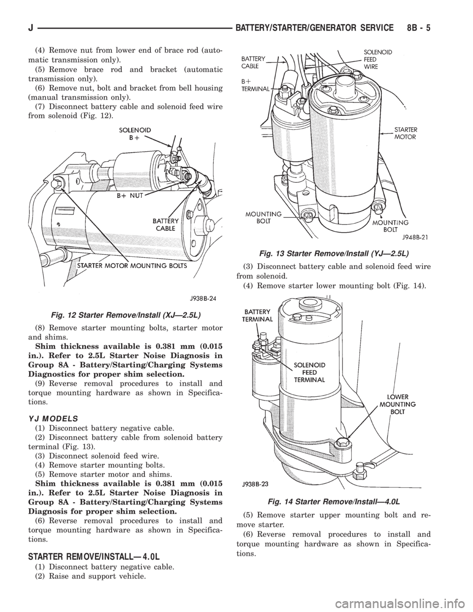
(7) Disconnect battery cable and solenoid feed wire
from solenoid (Fig. 12).
(8) Remove starter mounting bolts, starter motor
and shims.
Shim thickness available is 0.381 mm (0.015
in.). Refer to 2.5L Starter Noise Diagnosis in
Group 8A - Battery/Starting/Charging Systems
Diagnostics for proper shim selection.
(9) Reverse removal procedures to install and
torque mounting hardware as shown in Specifica-
tions.
YJ MODELS
(1) Disconnect battery negative cable.
(2) Disconnect battery cable from solenoid battery
terminal (Fig. 13).
(3) Disconnect solenoid feed wire.
(4) Remove starter mounting bolts.
(5) Remove starter motor and shims.
Shim thickness available is 0.381 mm (0.015
in.). Refer to 2.5L Starter Noise Diagnosis in
Group 8A - Battery/Starting/Charging Systems
Diagnosis for proper shim selection.
(6) Reverse removal procedures to install and
torque mounting hardware as shown in Specifica-
tions.
STARTER REMOVE/INSTALLÐ4.0L
(1) Disconnect battery negative cable.
(2) Raise and support vehicle.(3) Disconnect battery cable and solenoid feed wire
from solenoid.
(4) Remove starter lower mounting bolt (Fig. 14).
(5) Remove starter upper mounting bolt and re-
move starter.
(6) Reverse removal procedures to install and
torque mounting hardware as shown in Specifica-
tions.
Fig. 12 Starter Remove/Install (XJÐ2.5L)
Fig. 13 Starter Remove/Install (YJÐ2.5L)
Fig. 14 Starter Remove/InstallÐ4.0L
JBATTERY/STARTER/GENERATOR SERVICE 8B - 5