tow JEEP COMPASS 2020 Owner handbook (in English)
[x] Cancel search | Manufacturer: JEEP, Model Year: 2020, Model line: COMPASS, Model: JEEP COMPASS 2020Pages: 328, PDF Size: 8.85 MB
Page 174 of 328
STARTING AND OPERATING
172
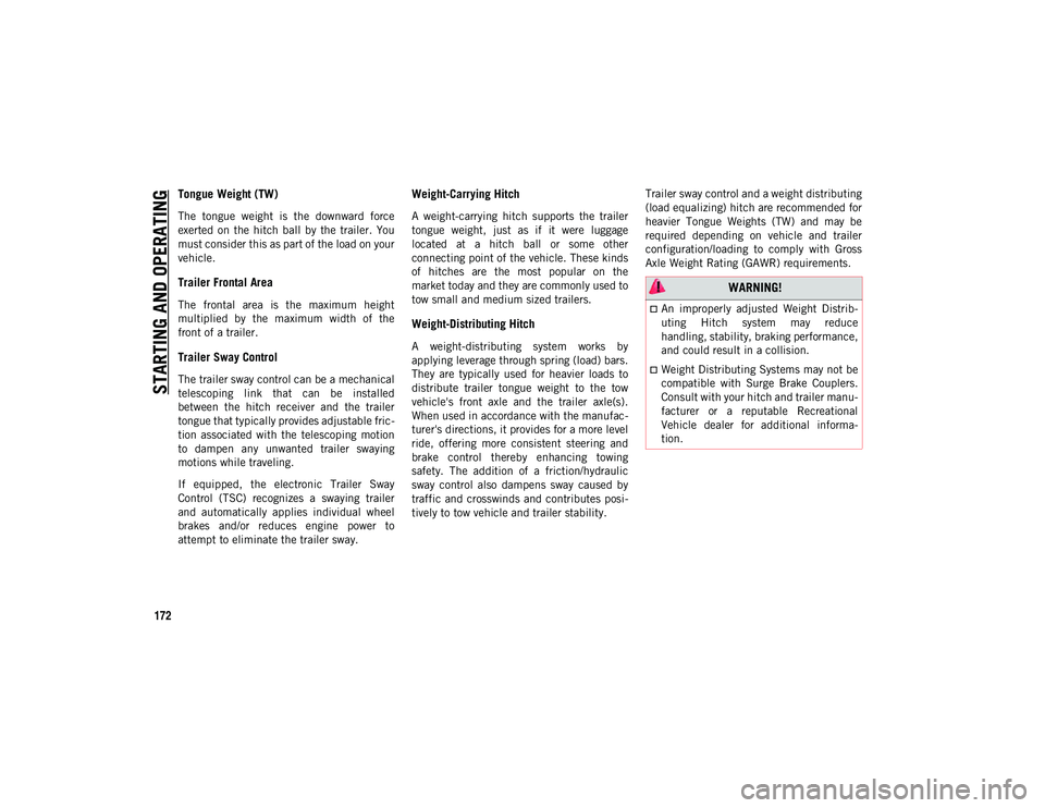
Tongue Weight (TW)
The tongue weight is the downward force
exerted on the hitch ball by the trailer. You
must consider this as part of the load on your
vehicle.
Trailer Frontal Area
The frontal area is the maximum height
multiplied by the maximum width of the
front of a trailer.
Trailer Sway Control
The trailer sway control can be a mechanical
telescoping link that can be installed
between the hitch receiver and the trailer
tongue that typically provides adjustable fric-
tion associated with the telescoping motion
to dampen any unwanted trailer swaying
motions while traveling.
If equipped, the electronic Trailer Sway
Control (TSC) recognizes a swaying trailer
and automatically applies individual wheel
brakes and/or reduces engine power to
attempt to eliminate the trailer sway.
Weight-Carrying Hitch
A weight-carrying hitch supports the trailer
tongue weight, just as if it were luggage
located at a hitch ball or some other
connecting point of the vehicle. These kinds
of hitches are the most popular on the
market today and they are commonly used to
tow small and medium sized trailers.
Weight-Distributing Hitch
A weight-distributing system works by
applying leverage through spring (load) bars.
They are typically used for heavier loads to
distribute trailer tongue weight to the tow
vehicle's front axle and the trailer axle(s).
When used in accordance with the manufac -
turer's directions, it provides for a more level
ride, offering more consistent steering and
brake control thereby enhancing towing
safety. The addition of a friction/hydraulic
sway control also dampens sway caused by
traffic and crosswinds and contributes posi -
tively to tow vehicle and trailer stability. Trailer sway control and a weight distributing
(load equalizing) hitch are recommended for
heavier Tongue Weights (TW) and may be
required depending on vehicle and trailer
configuration/loading to comply with Gross
Axle Weight Rating (GAWR) requirements.
WARNING!
An improperly adjusted Weight Distrib
-
uting Hitch system may reduce
handling, stability, braking performance,
and could result in a collision.
Weight Distributing Systems may not be
compatible with Surge Brake Couplers.
Consult with your hitch and trailer manu -
facturer or a reputable Recreational
Vehicle dealer for additional informa-
tion.
2020_JEEP_M6_UG_UK.book Page 172
Page 175 of 328
173
(Continued)
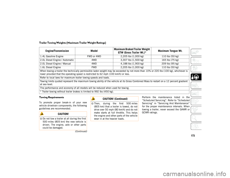
Trailer Towing Weights (Maximum Trailer Weight Ratings)
Towing Requirements
To promote proper break-in of your new
vehicle drivetrain components, the following
guidelines are recommended.Perform the maintenance listed in the
“Scheduled Servicing”. Refer to “Scheduled
Servicing” in “Servicing And Maintenance”
for the proper maintenance intervals. When
towing a trailer, never exceed the GAWR or
GCWR ratings.
Engine/Transmission
ModelMaximum Braked Trailer Weight
GTW (Gross Trailer Wt.)* Maximum Tongue Wt.
1.4L Gasoline Engine
FWD or 4WD2,205 lbs (1,000 kg) 110 lbs (50 kg)
2.0L Diesel Engine / Automatic 4WD3,307 lbs (1,500 kg) 165 lbs (75 kg)
2.0L Diesel Engine / Manual 4WD4,188 lbs (1,900 kg) 209 lbs (95 kg)
1.6L Diesel Engine FWD2,205 lbs (1,000 kg) 110 lbs (50 kg)
When towing a trailer the technically permissible laden weight may be exceeded by not more than 10% or 220 lbs (100 kg), whichever is
lower provided that the operating speed is restricted to 62 mph (100 km/h) or less.
Refer to local laws for maximum trailer towing speeds and loads.
Towing limits quoted represent the maximum towing ability of the vehicle at its Gross Combined Mass to restart on a 12 percent gradient
at sea level.
The performance and economy of all models will be reduced when used for towing.
* Trailer towing without trailer brakes is limited to 992 lbs (450 kg).
CAUTION!
Do not tow a trailer at all during the first
500 miles (805 km) the new vehicle is
driven. The engine, axle or other parts
could be damaged.
Then, during the first 500 miles
(805 km) that a trailer is towed, do not
drive over 50 mph (80 km/h) and do not
make starts at full throttle. This helps
the engine and other parts of the vehicle
wear in at the heavier loads.
CAUTION! (Continued)
2020_JEEP_M6_UG_UK.book Page 173
Page 176 of 328
STARTING AND OPERATING
174
(Continued)
(Continued)
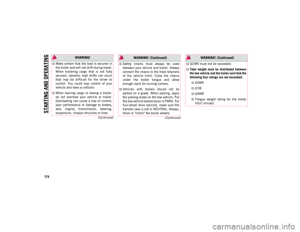
WARNING!
Make certain that the load is secured in
the trailer and will not shift during travel.
When trailering cargo that is not fully
secured, dynamic load shifts can occur
that may be difficult for the driver to
control. You could lose control of your
vehicle and have a collision.
When hauling cargo or towing a trailer,
do not overload your vehicle or trailer.
Overloading can cause a loss of control,
poor performance or damage to brakes,
axle, engine, transmission, steering,
suspension, chassis structure or tires.
Safety chains must always be used
between your vehicle and trailer. Always
connect the chains to the hook retainers
of the vehicle hitch. Cross the chains
under the trailer tongue and allow
enough slack for turning corners.
Vehicles with trailers should not be
parked on a grade. When parking, apply
the parking brake on the tow vehicle. Put
the tow vehicle transmission in PARK. For
four-wheel drive vehicles, make sure the
transfer case is not in NEUTRAL. Always,
block or "chock" the trailer wheels.
WARNING! (Continued)
GCWR must not be exceeded.
Total weight must be distributed between
the tow vehicle and the trailer such that the
following four ratings are not exceeded
:
GVWR
GTW
GAWR
Tongue weight rating for the trailer
hitch utilized.
WARNING! (Continued)
2020_JEEP_M6_UG_UK.book Page 174
Page 177 of 328
175
RECREATIONAL TOWING (BEHIND MOTORHOME, ETC.)
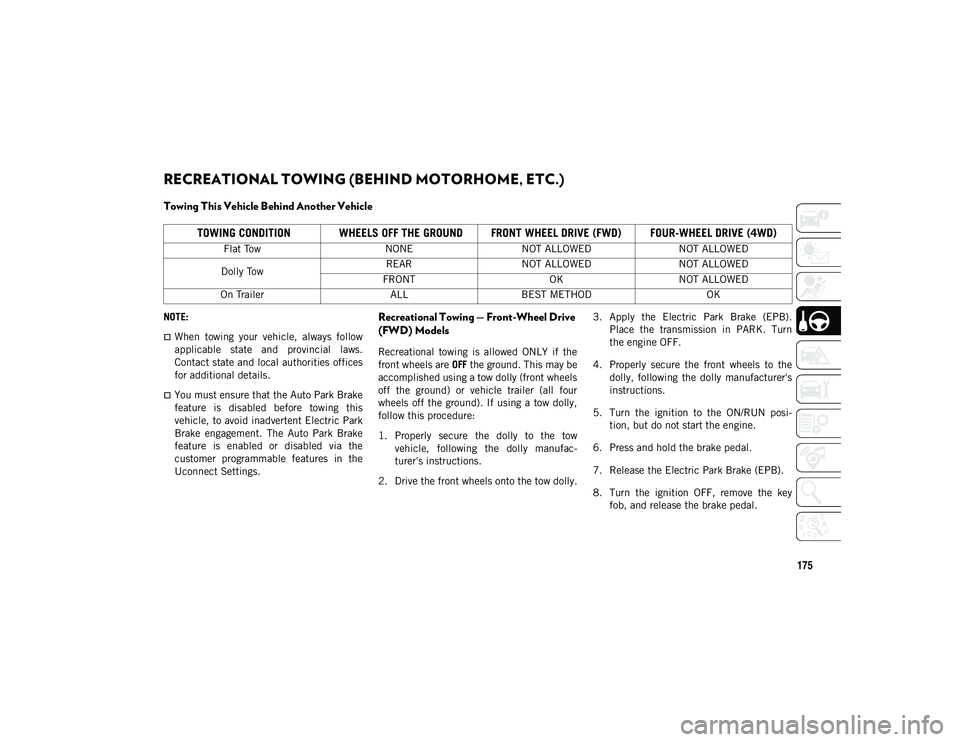
Towing This Vehicle Behind Another Vehicle
NOTE:
When towing your vehicle, always follow
applicable state and provincial laws.
Contact state and local authorities offices
for additional details.
You must ensure that the Auto Park Brake
feature is disabled before towing this
vehicle, to avoid inadvertent Electric Park
Brake engagement. The Auto Park Brake
feature is enabled or disabled via the
customer programmable features in the
Uconnect Settings.
Recreational Towing — Front-Wheel Drive
(FWD) Models
Recreational towing is allowed ONLY if the
front wheels are OFF the ground. This may be
accomplished using a tow dolly (front wheels
off the ground) or vehicle trailer (all four
wheels off the ground). If using a tow dolly,
follow this procedure:
1. Properly secure the dolly to the tow vehicle, following the dolly manufac -
turer's instructions.
2. Drive the front wheels onto the tow dolly. 3. Apply the Electric Park Brake (EPB).
Place the transmission in PARK. Turn
the engine OFF.
4. Properly secure the front wheels to the dolly, following the dolly manufacturer's
instructions.
5. Turn the ignition to the ON/RUN posi -
tion, but do not start the engine.
6. Press and hold the brake pedal.
7. Release the Electric Park Brake (EPB).
8. Turn the ignition OFF, remove the key fob, and release the brake pedal.
TOWING CONDITION WHEELS OFF THE GROUND FRONT WHEEL DRIVE (FWD) FOUR-WHEEL DRIVE (4WD)
Flat Tow NONENOT ALLOWED NOT ALLOWED
Dolly Tow REAR
NOT ALLOWED NOT ALLOWED
FRONT OKNOT ALLOWED
On Trailer ALLBEST METHOD OK
2020_JEEP_M6_UG_UK.book Page 175
Page 178 of 328
STARTING AND OPERATING
176
Recreational Towing — 4X4 Models
Recreational towing (with all four wheels on
the ground, or using a towing dolly) is NOT
ALLOWED. This vehicle may be towed on
flatbed or vehicle trailer provided all four
wheels are OFF the ground.
CAUTION!
Towing with the front wheels on the
ground will cause severe transmission
damage. Damage from improper towing
is not covered under the New Vehicle
Limited Warranty.
Ensure that the Electric Park Brake is
released, and remains released, while
being towed.
Do not use a bumper mounted clamp-on
tow bar on your vehicle. The bumper face
will be damaged.
CAUTION!
Towing this vehicle with ANY of its wheels
on the ground can cause severe
transmission and/or power transfer unit
damage. Damage from improper towing is
not covered under the New Vehicle
Limited Warranty.
2020_JEEP_M6_UG_UK.book Page 176
Page 182 of 328
IN CASE OF EMERGENCY
180
Turn Signal Light/Position Lights/Daytime
Running Lights
To replace the bulbs proceed as follows:
1. Turn the front wheels completely.
2. Remove the wheel liner.
3. Remove the electrical connectors.
4. For the DRL bulb, grip the bulb at the topand bottom locking tabs and squeeze to
remove the bulb.
5. To replace the DRL bulb gently push bulb towards housing. Be sure to hear both the
top and bottom locking tabs “CLICK” to
ensure the bulb is properly seated.
6. For the turn signal bulb, rotate in a coun -
terclockwise direction and remove the
bulb and bulb socket. Pull the bulb
axially to remove it from the socket.
7. Install the bulb and sockets and rotate them clockwise making sure that it is
properly locked.
8. Reconnect the electrical connectors.
9. Reinstall the wheel liner.
NOTE:
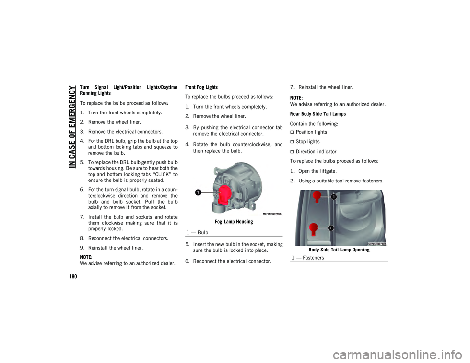
We advise referring to an authorized dealer. Front Fog Lights
To replace the bulbs proceed as follows:
1. Turn the front wheels completely.
2. Remove the wheel liner.
3. By pushing the electrical connector tab
remove the electrical connector.
4. Rotate the bulb counterclockwise, and then replace the bulb.
Fog Lamp Housing
5. Insert the new bulb in the socket, making sure the bulb is locked into place.
6. Reconnect the electrical connector. 7. Reinstall the wheel liner.
NOTE:
We advise referring to an authorized dealer.
Rear Body Side Tail Lamps
Contain the following:
Position lights
Stop lights
Direction indicator
To replace the bulbs proceed as follows:
1. Open the liftgate.
2. Using a suitable tool remove fasteners.
Body Side Tail Lamp Opening
1 — Bulb
1 — Fasteners
2020_JEEP_M6_UG_UK.book Page 180
Page 185 of 328
183
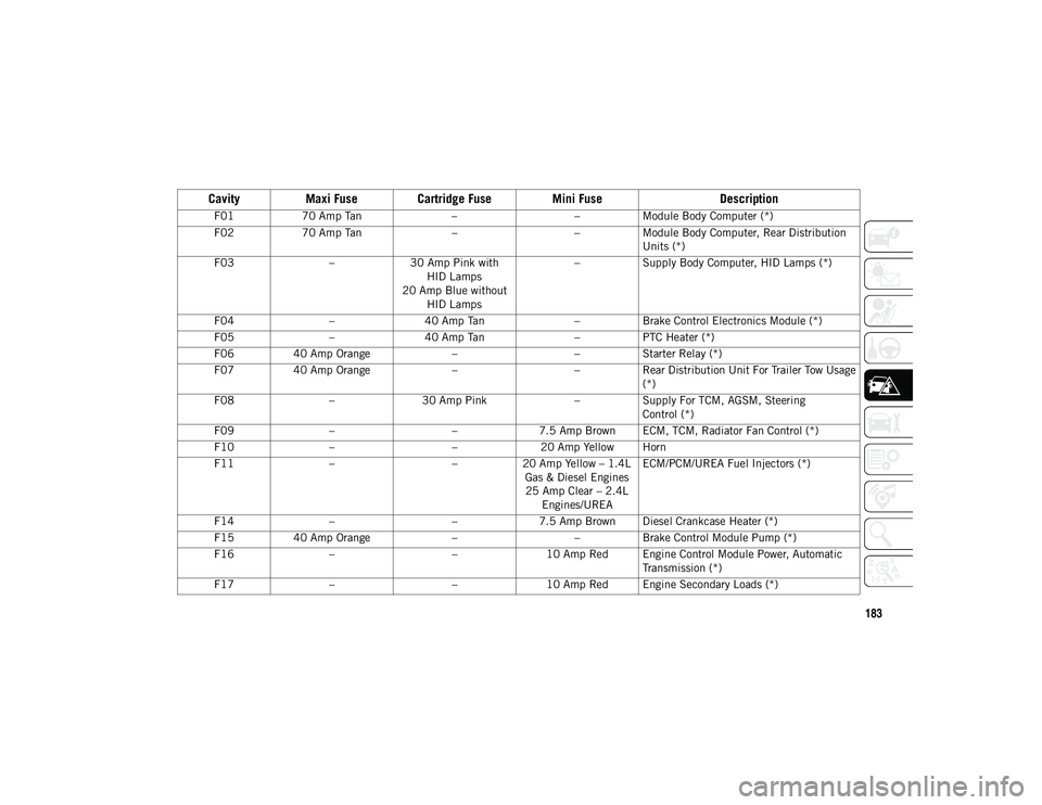
Cavity
Maxi Fuse Cartridge Fuse Mini Fuse Description
F0170 Amp Tan ––Module Body Computer (*)
F02 70 Amp Tan ––Module Body Computer, Rear Distribution
Units (*)
F03 –30 Amp Pink with
HID Lamps
20 Amp Blue without HID Lamps –
Supply Body Computer, HID Lamps (*)
F04 –40 Amp Tan –Brake Control Electronics Module (*)
F05 –40 Amp Tan –PTC Heater (*)
F06 40 Amp Orange ––Starter Relay (*)
F07 40 Amp Orange ––Rear Distribution Unit For Trailer Tow Usage
(*)
F08 –30 Amp Pink –Supply For TCM, AGSM, Steering
Control (*)
F09 – –7.5 Amp Brown ECM, TCM, Radiator Fan Control (*)
F10 – –20 Amp Yellow Horn
F11 – –20 Amp Yellow – 1.4L
Gas & Diesel Engines25 Amp Clear – 2.4L Engines/UREA ECM/PCM/UREA Fuel Injectors (*)
F14 – –7.5 Amp Brown Diesel Crankcase Heater (*)
F15 40 Amp Orange ––Brake Control Module Pump (*)
F16 – –10 Amp Red Engine Control Module Power, Automatic
Transmission (*)
F17 – –10 Amp Red Engine Secondary Loads (*)
2020_JEEP_M6_UG_UK.book Page 183
Page 188 of 328
IN CASE OF EMERGENCY
186
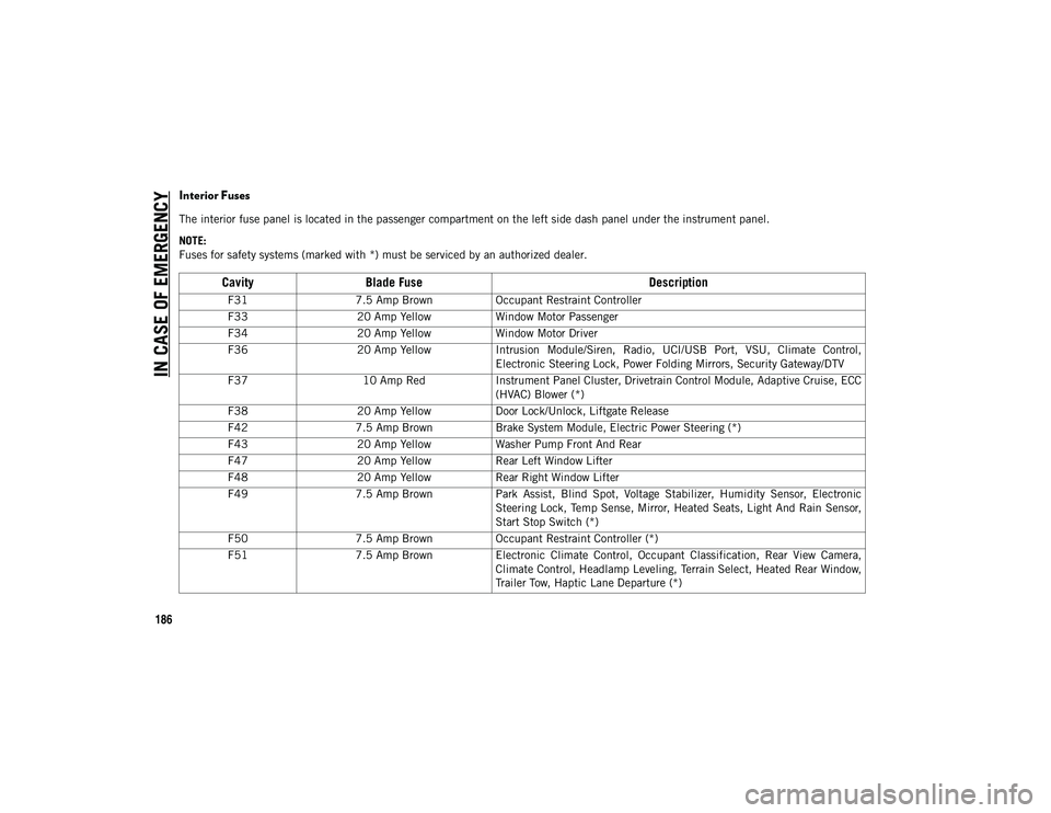
Interior Fuses
The interior fuse panel is located in the passenger compartment on the left side dash panel under the instrument panel.
NOTE:
Fuses for safety systems (marked with *) must be serviced by an authorized dealer.
CavityBlade Fuse Description
F317.5 Amp Brown Occupant Restraint Controller
F33 20 Amp Yellow Window Motor Passenger
F34 20 Amp Yellow Window Motor Driver
F36 20 Amp Yellow Intrusion Module/Siren, Radio, UCI/USB Port, VSU, Climate Control,
Electronic Steering Lock, Power Folding Mirrors, Security Gateway/DTV
F37 10 Amp RedInstrument Panel Cluster, Drivetrain Control Module, Adaptive Cruise, ECC
(HVAC) Blower (*)
F38 20 Amp Yellow Door Lock/Unlock, Liftgate Release
F42 7.5 Amp Brown Brake System Module, Electric Power Steering (*)
F43 20 Amp Yellow Washer Pump Front And Rear
F47 20 Amp Yellow Rear Left Window Lifter
F48 20 Amp Yellow Rear Right Window Lifter
F49 7.5 Amp Brown Park Assist, Blind Spot, Voltage Stabilizer, Humidity Sensor, Electronic
Steering Lock, Temp Sense, Mirror, Heated Seats, Light And Rain Sensor,
Start Stop Switch (*)
F50 7.5 Amp Brown Occupant Restraint Controller (*)
F51 7.5 Amp Brown Electronic Climate Control, Occupant Classification, Rear View Camera,
Climate Control, Headlamp Leveling, Terrain Select, Heated Rear Window,
Trailer Tow, Haptic Lane Departure (*)
2020_JEEP_M6_UG_UK.book Page 186
Page 189 of 328
187
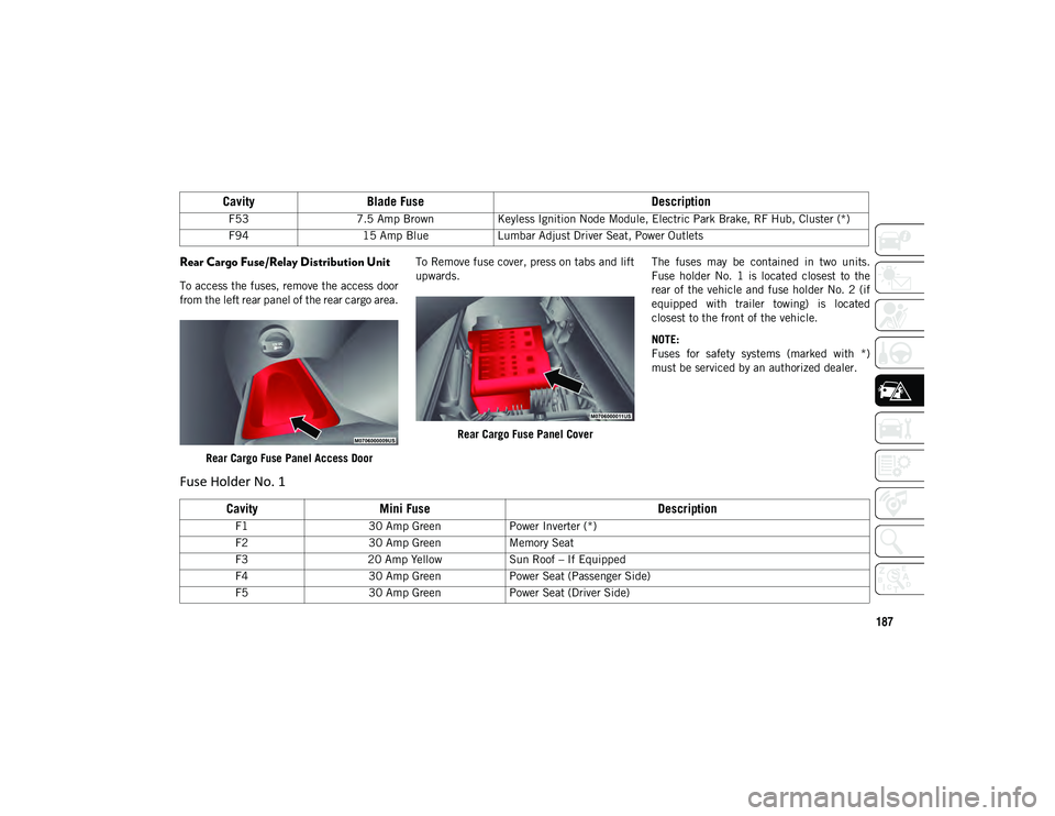
Rear Cargo Fuse/Relay Distribution Unit
To access the fuses, remove the access door
from the left rear panel of the rear cargo area.Rear Cargo Fuse Panel Access Door To Remove fuse cover, press on tabs and lift
upwards.
Rear Cargo Fuse Panel Cover The fuses may be contained in two units.
Fuse holder No. 1 is located closest to the
rear of the vehicle and fuse holder No. 2 (if
equipped with trailer towing) is located
closest to the front of the vehicle.
NOTE:
Fuses for safety systems (marked with *)
must be serviced by an authorized dealer.
F53
7.5 Amp Brown Keyless Ignition Node Module, Electric Park Brake, RF Hub, Cluster (*)
F94 15 Amp Blue Lumbar Adjust Driver Seat, Power Outlets
CavityBlade Fuse Description
Fuse Holder No. 1
CavityMini Fuse Description
F130 Amp Green Power Inverter (*)
F2 30 Amp Green Memory Seat
F3 20 Amp Yellow Sun Roof – If Equipped
F4 30 Amp Green Power Seat (Passenger Side)
F5 30 Amp Green Power Seat (Driver Side)
2020_JEEP_M6_UG_UK.book Page 187
Page 191 of 328
189
JACKING AND TIRE
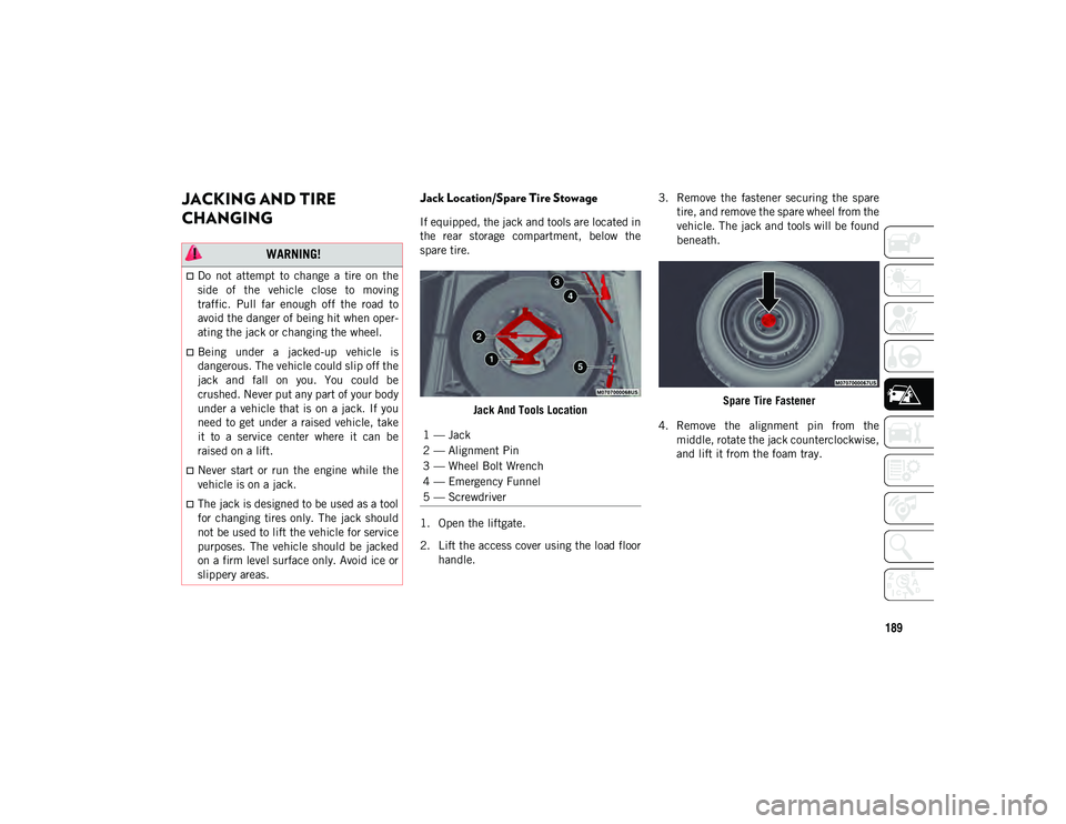
CHANGING Jack Location/Spare Tire Stowage
If equipped, the jack and tools are located in
the rear storage compartment, below the
spare tire.Jack And Tools Location
1. Open the liftgate.
2. Lift the access cover using the load floor handle. 3. Remove the fastener securing the spare
tire, and remove the spare wheel from the
vehicle. The jack and tools will be found
beneath.
Spare Tire Fastener
4. Remove the alignment pin from the middle, rotate the jack counterclockwise,
and lift it from the foam tray.
WARNING!
Do not attempt to change a tire on the
side of the vehicle close to moving
traffic. Pull far enough off the road to
avoid the danger of being hit when oper -
ating the jack or changing the wheel.
Being under a jacked-up vehicle is
dangerous. The vehicle could slip off the
jack and fall on you. You could be
crushed. Never put any part of your body
under a vehicle that is on a jack. If you
need to get under a raised vehicle, take
it to a service center where it can be
raised on a lift.
Never start or run the engine while the
vehicle is on a jack.
The jack is designed to be used as a tool
for changing tires only. The jack should
not be used to lift the vehicle for service
purposes. The vehicle should be jacked
on a firm level surface only. Avoid ice or
slippery areas.
1 — Jack
2 — Alignment Pin
3 — Wheel Bolt Wrench
4 — Emergency Funnel
5 — Screwdriver
2020_JEEP_M6_UG_UK.book Page 189