ESP JEEP GRAND CHEROKEE 2012 Owner handbook (in English)
[x] Cancel search | Manufacturer: JEEP, Model Year: 2012, Model line: GRAND CHEROKEE, Model: JEEP GRAND CHEROKEE 2012Pages: 380, PDF Size: 3.21 MB
Page 247 of 380
CAUTION!
Extreme steering maneuvers may cause the
electrically driven pump to reduce or stop
power steering assistance in order to prevent
damage to the system. Normal operation will
resume once the system is allowed to cool.If the “SERVICE POWER STEER-
ING SYSTEM” message and a
flashing icon are displayed on the
EVIC screen, it indicates that the
vehicle needs to be taken to the
dealer for service. It is likely the
vehicle has lost power steering assistance.
Refer to “Electronic Vehicle Information (EVIC)”
in “Understanding Your Instrument Panel” for
further information.
If the “POWER STEERING SYSTEM OVER
TEMP” message and an icon are displayed on
the EVIC screen, it indicates that extreme steer-
ing maneuvers may have occurred, which
caused an over temperature condition in the
power steering system. You will lose power
steering assistance momentarily until the over
temperature condition no longer exists. Once driving conditions are safe, then pull over and
let vehicle idle for a few moments until the light
turns off. Refer to “Electronic Vehicle Informa-
tion (EVIC)” in “Understanding Your Instrument
Panel” for further information.
NOTE:
•
Even if power steering assistance is no
longer operational, it is still possible to
steer the vehicle. Under these conditions
there will be a substantial increase in
steering effort, especially at very low ve-
hicle speeds and during parking maneu-
vers.
• If the condition persists, see your autho-
rized dealer for service.
Power Steering Fluid CheckChecking the power steering fluid level at a
defined service interval is not required. The
fluid should only be checked if a leak is sus-
pected, abnormal noises are apparent, and/or
the system is not functioning as anticipated.
Coordinate inspection efforts through an autho-
rized dealer.
CAUTION!
Do not use chemical flushes in your power
steering system as the chemicals can dam-
age your power steering components. Such
damage is not covered by the New Vehicle
Limited Warranty.
WARNING!
Fluid level should be checked on a level
surface and with the engine off to prevent
injury from moving parts and to ensure accu-
rate fluid level reading. Do not overfill. Use
only manufacturer’s recommended power
steering fluid.
If necessary, add fluid to restore to the proper
indicated level. With a clean cloth, wipe any
spilled fluid from all surfaces. Refer to “Fluids,
Lubricants, and Genuine Parts” in “Maintaining
Your Vehicle” for further information.
243
Page 251 of 380
ERM can only reduce the chance of wheel lift
occurring during severe or evasive driving ma-
neuvers. It cannot prevent wheel lift due to
other factors such as road conditions, leaving
the roadway or striking objects or other ve-
hicles.
WARNING!
Many factors, such as vehicle loading, road
conditions and driving conditions, influence
the chance that wheel lift or rollover may
occur. ERM cannot prevent all wheel lift or
rollovers, especially those that involve leaving
the roadway or striking objects or other ve-
hicles. The capabilities of an ERM-equipped
vehicle must never be exploited in a reckless
or dangerous manner which could jeopardize
the user’s safety or the safety of others.
Electronic Stability Control (ESC)
This system enhances directional control and
stability of the vehicle under various driving
conditions. ESC corrects for oversteering or
understeering of the vehicle by applying the
brake of the appropriate wheel to assist incounteracting the oversteer or understeer con-
dition. Engine power may also be reduced to
help the vehicle maintain the desired path.
ESC uses sensors in the vehicle to determine
the vehicle path intended by the driver and
compares it to the actual path of the vehicle.
When the actual path does not match the
intended path, ESC applies the brake of the
appropriate wheel to assist in counteracting the
oversteer or understeer condition.
•
Oversteer - when the vehicle is turning more
than appropriate for the steering wheel po-
sition.
• Understeer - when the vehicle is turning less
than appropriate for the steering wheel po-
sition.
The “ESC Activation/Malfunction Indicator
Light” located in the instrument cluster will start
to flash as soon as the tires lose traction and
the ESC system becomes active. The “ESC
Activation/Malfunction Indicator Light” also
flashes when the TCS is active. If the “ESC
Activation/Malfunction Indicator Light” begins
to flash during acceleration, ease up on the
accelerator and apply as little throttle as pos- sible. Be sure to adapt your speed and driving
to the prevailing road conditions.
WARNING!
The Electronic Stability Control (ESC) cannot
prevent the natural laws of physics from act-
ing on the vehicle, nor can it increase the
traction afforded by prevailing road condi-
tions. ESC cannot prevent accidents, includ-
ing those resulting from excessive speed in
turns, driving on very slippery surfaces, or
hydroplaning. The capabilities of an ESC
equipped vehicle must never be exploited in a
reckless or dangerous manner which could
jeopardize the user’s safety or the safety of
others.
The ESC system has two available operating
modes in 4WD HIGH range, and one operating
mode in 4WD LOW range.
High Range (Four-Wheel Drive Models)
On
This is the normal operating mode for ESC in
4WD HIGH range. Whenever the vehicle is 247
Page 253 of 380
information. When TSC is functioning, the “ESC
Activation/Malfunction Indicator Light” will
flash, the engine power may be reduced and
you may feel the brakes being applied to
individual wheels to attempt to stop the trailer
from swaying. TSC is disabled when the ESC
system is in the “Partial Off” mode.
WARNING!
If TSC activates while driving, slow the vehicle
down, stop at the nearest safe location, and
adjust the trailer load to eliminate trailer sway.
Hill Start Assist (HSA)The HSA system is designed to assist the driver
when starting a vehicle from a stop on a hill.
HSA will maintain the level of brake pressure
the driver applied for a short period of time after
the driver takes their foot off of the brake pedal.
If the driver does not apply the throttle during
this short period of time, the system will release
brake pressure and the vehicle will roll down
the hill. The system will release brake pressure
in proportion to the amount of throttle applied
as the vehicle starts to move in the intended
direction of travel.HSA Activation Criteria
The following criteria must be met in order for
HSA to activate:
•
Vehicle must be stopped.
• Vehicle must be on a 6% (approximate)
grade or greater hill.
• Gear selection matches vehicle uphill direc-
tion (i.e., vehicle facing uphill is in forward
gear; vehicle backing uphill is in REVERSE
gear).
HSA will work in REVERSE and all forward
gears when the activation criteria have been
met. The system will not activate if the vehicle is
placed in NEUTRAL or PARK.
WARNING!
There may be situations on minor hills (i.e.,
less than 8%), with a loaded vehicle, or while
pulling a trailer, when the system will not
activate and slight rolling may occur. This
could cause a collision with another vehicle or
object. Always remember the driver is respon-
sible for braking the vehicle. Towing With HSA
HSA will provide assistance when starting on a
grade when pulling a trailer.
WARNING!
•
If you use a trailer brake controller with your
trailer, your trailer brakes may be activated
and deactivated with the brake switch. If so,
when the brake pedal is released, there
may not be enough brake pressure to hold
the vehicle and trailer on a hill and this
could cause a collision with another vehicle
or object behind you. In order to avoid
rolling down the hill while resuming accel-
eration, manually activate the trailer brake
prior to releasing the brake pedal. Always
remember the driver is responsible for
braking the vehicle.
(Continued)
249
Page 254 of 380
WARNING!(Continued)
• HSA is not a parking brake. If you stop the
vehicle on a hill without putting the trans-
mission in PARK and using the parking
brake, it will roll down the hill and could
cause a collision with another vehicle or
object. Always remember to use the park-
ing brake while parking on a hill, and that
the driver is responsible for braking the
vehicle.
HSA Off
If you wish to turn off the HSA system, it can be
done using the Customer Programmable Fea-
tures in the Electronic Vehicle Information Cen-
ter (EVIC). Refer to “Electronic Vehicle Informa-
tion Center (EVIC)” in “Understanding Your
Instrument Panel” for further information.
Ready Alert BrakingReady Alert Braking may reduce the time re-
quired to reach full braking during emergency
braking situations. It anticipates when an emer-
gency braking situation may occur by monitor-
ing how fast the throttle is released by the driver. When the throttle is released very
quickly, Ready Alert Braking applies a small
amount of brake pressure. This brake pressure
will not be noticed by the driver. The brake
system uses this brake pressure to allow a fast
brake response if the driver applies the brakes.
Rain Brake SupportRain Brake Support may improve braking per-
formance in wet conditions. It will periodically
apply a small amount of brake pressure to
remove any water buildup on the front brake
rotors. It only functions when the windshield
wipers are in the LO or HI mode, it does not
function in the intermittent mode. When Rain
Brake Support is active, there is no notification
to the driver and no driver interaction is re-
quired.
Hill Descent Control (HDC) —
Four-Wheel Drive Models With
MP3023 Two-Speed Transfer Case
Only
HDC maintains vehicle speed while descend-
ing hills during off-road driving situations and is
available in 4WD LOW range only. To enable
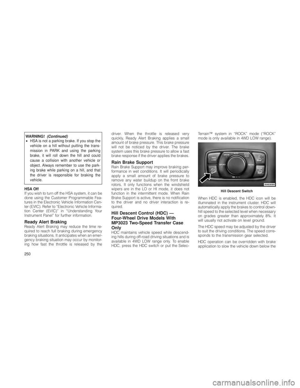
HDC, press the HDC switch or put the Selec-Terrain™ system in “ROCK” mode (“ROCK”
mode is only available in 4WD LOW range).
When HDC is enabled, the HDC icon will be
illuminated in the instrument cluster. HDC will
automatically apply the brakes to control down-
hill speed to the selected level when necessary
on grades greater than approximately 8%. It
will usually not activate on level ground.
The HDC speed may be adjusted by the driver
to suit the driving conditions. The speed corre-
sponds to the transmission gear selected.
HDC operation can be overridden with brake
application to slow the vehicle down below the
Hill Descent Switch
250
Page 255 of 380
HDC control speed. Conversely, if more speed
is desired during HDC control, the accelerator
pedal will increase vehicle speed in the usual
manner. When either the brake or the accelera-
tor is released, HDC will control the vehicle
back to the original set speed.
HDC Operation in 4WD Low Range
To enable HDC, press the HDC switch or put
the Selec-Terrain™ system in the “ROCK”
mode. The HDC icon will be illuminated in the
instrument cluster and HDC will function. If the
vehicle speed goes above 20 mph (32 km/h),
the HDC icon will flash and HDC will not
function. To disable HDC, press the HDC
switch.
4WD Low Range Set Speeds
•1st = 1 mph (1.6 km/h)
• 2nd = 2.5 mph (4 km/h)
• 3rd = 4 mph (6 km/h)
• 4th = 5.5 mph (9 km/h)
• 5th or D (Drive) = 7.5 mph (12 km/h)
• REVERSE = 1 mph (1.6 km/h)
• NEUTRAL = 2.5 mph (4 km/h) •
PARK = HDC will not function
HDC is intended for low speed off-road driv-
ing only. At vehicle speeds above 20 mph
(32 km/h), HDC will no longer function. When
the vehicle speed drops below 20 mph
(32 km/h), HDC function will automatically re-
sume and the vehicle speed will return to the
chosen set speed.
WARNING!
HDC is only intended to assist the driver in
controlling vehicle speed when descending
hills. The driver must remain attentive to the
driving conditions and is responsible for main-
taining a safe vehicle speed.
ESC Activation/Malfunction Indicator
Light and ESC OFF Indicator Light
The “ESC Activation/Malfunction
Indicator Light” in the instrument
cluster will come on when the igni-
tion switch is turned to the ON
position. It should turn off with the
engine running. If the “ESC
Activation/Malfunction Indicator Light” comes on continuously with the engine running, a
malfunction has been detected in the ESC
system. If this light remains on after several
ignition cycles, and the vehicle has been driven
several miles (kilometers) at speeds greater
than 30 mph (48 km/h), see your authorized
dealer as soon as possible to have the problem
diagnosed and corrected.
The “ESC Activation/Malfunction Indicator
Light” (located in the instrument cluster) starts
to flash as soon as the tires lose traction and
the ESC system becomes active. The “ESC
Activation/Malfunction Indicator Light” also
flashes when TCS is active. If the “ESC
Activation/Malfunction Indicator Light” begins
to flash during acceleration, ease up on the
accelerator and apply as little throttle as pos-
sible. Be sure to adapt your speed and driving
to the prevailing road conditions.
NOTE:
•
The “ESC Activation/Malfunction Indica-
tor Light” and the “ESC OFF Indicator
Light” come on momentarily each time
the ignition switch is turned ON.
251
Page 256 of 380
•Each time the ignition is turned ON, the
ESC system will be ON even if it was
turned off previously.
• The ESC system will make buzzing or
clicking sounds when it is active. This is
normal; the sounds will stop when ESC
becomes inactive following the maneuver
that caused the ESC activation.
The “ESC OFF Indicator Light” in-
dicates the Electronic Stability
Control (ESC) is off.
TIRES — GENERAL INFORMATION
Tire Pressure
Proper tire inflation pressure is essential to the
safe and satisfactory operation of your vehicle.
Three primary areas are affected by improper
tire pressure: Safety
WARNING!
•
Improperly inflated tires are dangerous and
can cause accidents.
• Under-inflation increases tire flexing and
can result in tire failure.
• Over-inflation reduces a tire’s ability to
cushion shock. Objects on the road and
chuck holes can cause damage that results
in tire failure.
• Unequal tire pressures can cause steering
problems. You could lose control of your
vehicle.
• Over-inflated or under-inflated tires can af-
fect vehicle handling and can fail suddenly,
resulting in loss of vehicle control.
Always drive with each tire inflated to the
recommended pressure. Economy
Improper inflation pressures can cause uneven
wear patterns to develop across the tire tread.
These abnormal wear patterns will reduce
tread life resulting in a need for earlier tire
replacement. Under-inflation also increases tire
rolling resistance and results in higher fuel
consumption.
Ride Comfort and Vehicle Stability
Proper tire inflation contributes to a comfortable
ride. Over-inflation produces a jarring and un-
comfortable ride. Both under-inflation and over-
inflation affect the stability of the vehicle and
can produce a feeling of sluggish response or
over responsiveness in the steering.
Unequal tire pressures can cause erratic and
unpredictable steering response.
Unequal tire pressure from side to side may
cause the vehicle to drift left or right.
252
Page 258 of 380
WARNING!
Fast spinning tires can be dangerous. Forces
generated by excessive wheel speeds may
cause tire damage or failure. A tire could
explode and injure someone. Do not spin your
vehicle’s wheels faster than 30 mph (48 km/h)
when you are stuck, and do not let anyone
near a spinning wheel, no matter what the
speed.
Tire ChainsUse of traction devices require sufficient tire-to-
body clearance. Follow these recommenda-
tions to guard against damage.
•Install on Rear Tires Only
• Due to limited clearance, use SAE class “S”
low profile cables or traction devices only.
Security Chain Company (SCC) Super Z6
#SZ 441 cables or equivalent are recom-
mended.
WARNING!
Using tires of different size and type (M+S,
Snow) between front and rear axles can
cause unpredictable handling. You could lose
control and have a collision.
CAUTION!
To avoid damage to your vehicle or tires,
observe the following precautions:
• Because of restricted traction device clear-
ance between tires and other suspension
components, it is important that only trac-
tion devices in good condition are used.
Broken devices can cause serious dam-
age. Stop the vehicle immediately if noise
occurs that could indicate device breakage.
Remove the damaged parts of the device
before further use.
• Install device as tightly as possible and
then retighten after driving about 0.5 mile
(0.8 km).
• Do not exceed 30 mph (48 km/h).
(Continued)
CAUTION!(Continued)
• Drive cautiously and avoid severe turns
and large bumps, especially with a loaded
vehicle.
• Do not drive for prolonged period on dry
pavement.
• Observe the traction device manufacturer’s
instructions on the method of installation,
operating speed, and conditions for use.
Always use the suggested operating speed
of the device manufacturer’s if it is less than
30 mph (48 km/h).
• Do not use traction devices on a compact
spare tire.
Treadwear IndicatorsThese indicators are narrow strips 1/16 in
(1.6 mm) thick and are found in the tread
pattern grooves.
When the tread pattern is worn down to these
treadwear indicators, the tires should be re-
placed.
254
Page 260 of 380
WARNING!(Continued)
• Overloading your tires is dangerous. Like
under-inflation, overloading can cause tire
failure. Use tires of the recommended load
capacity for your vehicle — never overload
them.
CAUTION!
Replacing original tires with tires of a different
size may result in false speedometer and
odometer readings. This can also affect ve-
hicle performance and can do potential dam-
age to the driveline. Check with your dealer
before replacing tires with a different size.
Directional Tread Pattern Tires – If
Equipped
Your vehicle may be equipped with tires using
a directional tread pattern. These tires are
designed to optimize dry handling as well as
wet performance. To obtain the full benefits of
this design, the tires must be installed so that
they rotate in the correct direction. The rotation
direction of this type of tire is indicated by arrows on the side wall of the tire. The full size
spare tire is mounted as a direct replacement
for the right side of the vehicle. For a flat tire on
the left side of the vehicle, the full size spare
can be used as mounted. If this is required,
correct the rotation as soon as possible to
restore optimum wet performance.
TIRE ROTATION
RECOMMENDATIONS
Non-Directional Tires Only
Tires on the front and rear axles of vehicles
operate at different loads and perform different
steering, handling, and braking functions. For
these reasons, they wear at unequal rates.
These effects can be reduced by timely rotation
of tires. The benefits of rotation are especially
worthwhile with aggressive tread designs such
as those on On/Off-Road type tires. Rotation
will increase tread life, help to maintain mud,
snow, and wet traction levels, and contribute to
a smooth, quiet ride.
Refer to the “Maintenance Schedule” for the
proper maintenance intervals. More frequent
rotation is permissible if desired. The reasons
for any rapid or unusual wear should be cor-
rected prior to rotation being performed.
NOTE:
The premium Tire Pressure Monitor System
will automatically locate the pressure values
displayed in the correct vehicle position
following a tire rotation.
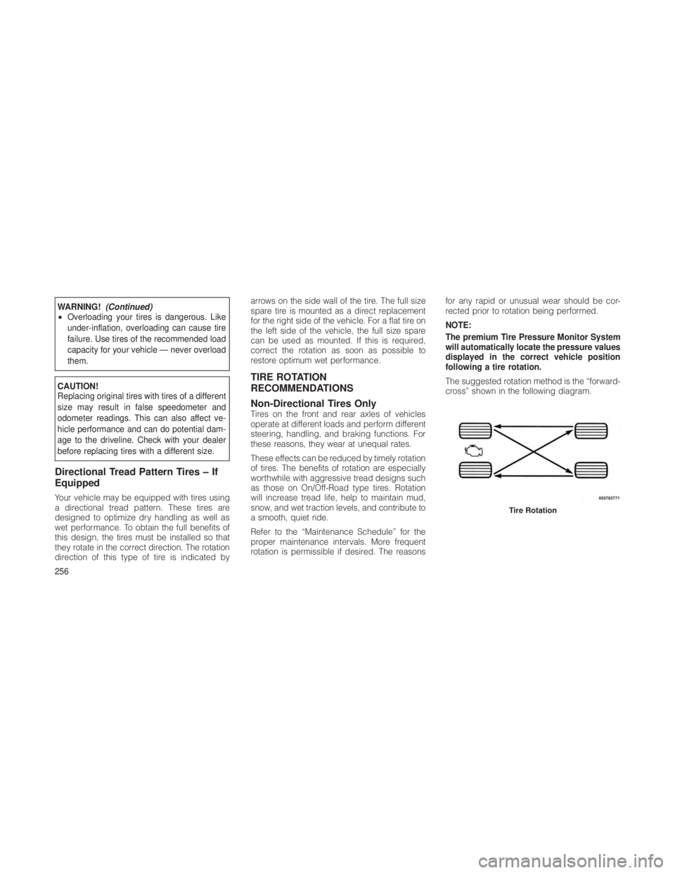
The suggested rotation method is the “forward-
cross” shown in the following diagram.
Tire Rotation
256
Page 262 of 380
CAUTION!(Continued)
• After inspecting or adjusting the tire pres-
sure always reinstall the valve stem cap.
This will prevent moisture and dirt from
entering the valve stem, which could dam-
age the Tire Pressure Monitoring Sensor.
NOTE:
• The TPMS is not intended to replace nor-
mal tire care and maintenance, or to pro-
vide warning of a tire failure or condition.
• The TPMS should not be used as a tire
pressure gauge while adjusting your tire
pressure.
• Driving on a significantly under-inflated
tire causes the tire to overheat and can
lead to tire failure. Under-inflation also
reduces fuel efficiency and tire tread life,
and may affect the vehicle’s handling and
stopping ability.
• The TPMS is not a substitute for proper
tire maintenance, and it is the driver’s
responsibility to maintain correct tire
pressure using an accurate tire gauge,
even if under-inflation has not reached the level to trigger the display of the “TPM
Telltale Light” and the “TIRE LOW PRES-
SURE” message.
• Seasonal temperature changes will affect
tire pressure, and the TPMS will monitor
the actual tire pressure in the tire.
Base SystemThe Tire Pressure Monitor System (TPMS) uses
wireless technology with wheel rim-mounted
electronic sensors to monitor tire pressure lev-
els. Sensors, mounted to each wheel as part of
the valve stem, transmit tire pressure readings
to the Receiver Module.
NOTE:
It is particularly important, for you to regu-
larly check the tire pressure in all of your
tires, and to maintain the proper pressure.
The TPMS consists of the following compo-
nents:
•Receiver Module
• Four Tire Pressure Monitoring Sensors
• Tire Pressure Monitoring Telltale Light A low spare tire will not cause the “Tire Pressure
Monitoring Telltale Light” to illuminate, a warn-
ing message to appear, or the chime to sound.
The “Tire Pressure Monitoring Telltale
Light” will illuminate in the instrument
cluster, a “TIRE LOW PRESSURE”
message will display in the instrument
cluster for 5 seconds, and an audible chime will
be activated, when one or more of the four
active road tire pressures are low. Should this
occur, you should stop as soon as possible,
check the inflation pressure of each tire on your
vehicle, and inflate each tire to the vehicle’s
recommended cold placard pressure value.
The system will automatically update and the
“Tire Pressure Monitoring Telltale Light” will
extinguish, once the updated tire pressures
have been received. The vehicle may need to
be driven for up to 20 minutes above 15 mph
(24 km/h) to receive this information.
The “Tire Pressure Monitoring Telltale Light” will
flash on and off for 75 seconds, and remain on
solid when a system fault is detected. In addi-
tion, a “SERVICE TPM SYSTEM” message may
be displayed for approximately 5 seconds
when a system fault is detected, and a chime
258
Page 267 of 380
Poor quality gasoline can cause problems such
as hard starting, stalling and stumble. If you
experience these problems, try another brand
of gasoline before considering service for the
vehicle.
Methanol
(Methyl or Wood Alcohol) is used in a variety of
concentrations when blended with unleaded
gasoline. You may find fuels containing 3% or
more Methanol along with other alcohols called
cosolvents. Problems that result from using
Methanol/gasoline or E-85 Ethanol blends are
not the responsibility of the manufacturer. While
MTBE is an oxygenate made from Methanol, it
does not have the negative effects of Methanol.
CAUTION!
Do not use gasolines containing Methanol or
E-85 Ethanol. Use of these blends may result
in starting and driveability problems and may
damage critical fuel system components.Ethanol
The manufacturer recommends that your ve-
hicle be operated on fuel containing no more
than 10% Ethanol. Purchasing your fuel from a
reputable supplier may reduce the risk of ex-
ceeding this 10% limit and/or of receiving fuel
with abnormal properties. It should also be
noted that an increase in fuel consumption
should be expected when using Ethanol-
blended fuels, due to the lower energy content
of Ethanol.
Problems that result from using Methanol/
gasoline or E-85 Ethanol blends are not the
responsibility of the manufacturer. While MTBE
is an oxygenate made from Methanol, it does
not have the negative effects of Methanol.CAUTION!
Use of fuel with Ethanol content higher than
10% may result in engine malfunction, starting
and operating difficulties and materials degra-
dation. These adverse effects could result in
permanent damage to your vehicle.Clean Air Gasoline
Many gasolines are now being blended that
contribute to cleaner air, especially in those
areas where air pollution levels are high. These
new blends provide a cleaner burning fuel and
some are referred to as “reformulated gaso-
line.”
The manufacturer supports these efforts toward
cleaner air. You can help by using these blends
as they become available.
MMT in Gasoline
MMT is a manganese containing metallic addi-
tive that is blended into some gasoline to
increase octane. Gasoline blended with MMT
provides no performance advantage beyond
gasoline of the same octane number without
MMT. Gasoline blended with MMT reduces
spark plug life and reduces emission system
performance in some vehicles. The manufac-
turer recommends that gasoline without MMT
be used in your vehicle. The MMT content of
gasoline may not be indicated on the gasoline
pump; therefore, you should ask your gasoline
retailer whether or not his/her gasoline contains
MMT.
263