display JEEP GRAND CHEROKEE 2012 Owner handbook (in English)
[x] Cancel search | Manufacturer: JEEP, Model Year: 2012, Model line: GRAND CHEROKEE, Model: JEEP GRAND CHEROKEE 2012Pages: 380, PDF Size: 3.21 MB
Page 230 of 380
Overdrive Operation
The automatic transmission includes an elec-
tronically controlled Overdrive (fifth gear). The
transmission will automatically shift into the
Overdrive gear if the following conditions are
present:
•the shift lever is in the DRIVE position,
• vehicle speed is sufficiently high, and
• the driver is not heavily pressing the accel-
erator.
Six-Speed Automatic Transmission
(5.7L Engine) — If Equipped
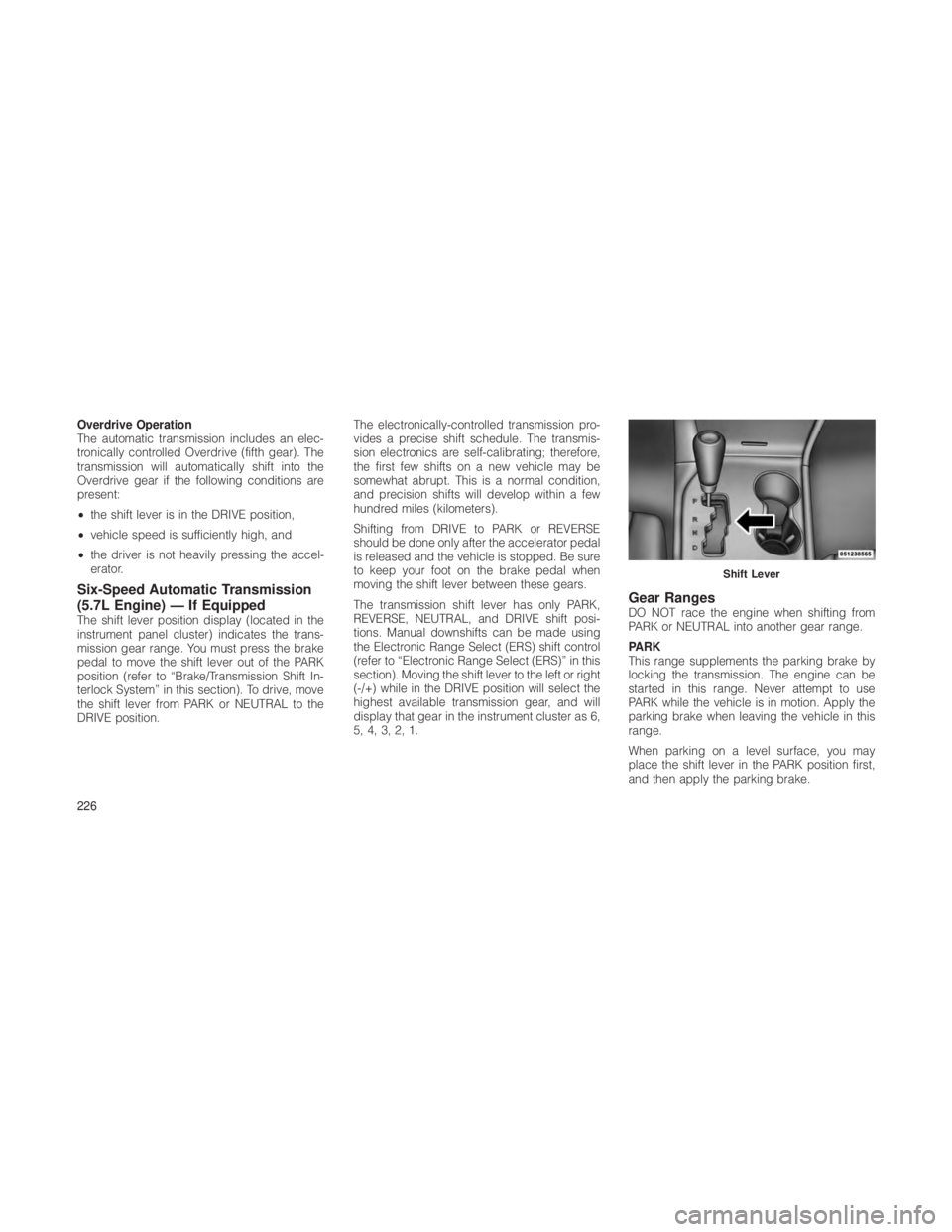
The shift lever position display (located in the
instrument panel cluster) indicates the trans-
mission gear range. You must press the brake
pedal to move the shift lever out of the PARK
position (refer to “Brake/Transmission Shift In-
terlock System” in this section). To drive, move
the shift lever from PARK or NEUTRAL to the
DRIVE position. The electronically-controlled transmission pro-
vides a precise shift schedule. The transmis-
sion electronics are self-calibrating; therefore,
the first few shifts on a new vehicle may be
somewhat abrupt. This is a normal condition,
and precision shifts will develop within a few
hundred miles (kilometers).
Shifting from DRIVE to PARK or REVERSE
should be done only after the accelerator pedal
is released and the vehicle is stopped. Be sure
to keep your foot on the brake pedal when
moving the shift lever between these gears.
The transmission shift lever has only PARK,
REVERSE, NEUTRAL, and DRIVE shift posi-
tions. Manual downshifts can be made using
the Electronic Range Select (ERS) shift control
(refer to “Electronic Range Select (ERS)” in this
section). Moving the shift lever to the left or right
(-/+) while in the DRIVE position will select the
highest available transmission gear, and will
display that gear in the instrument cluster as 6,
5, 4, 3, 2, 1.
Gear RangesDO NOT race the engine when shifting from
PARK or NEUTRAL into another gear range.
PARK
This range supplements the parking brake by
locking the transmission. The engine can be
started in this range. Never attempt to use
PARK while the vehicle is in motion. Apply the
parking brake when leaving the vehicle in this
range.
When parking on a level surface, you may
place the shift lever in the PARK position first,
and then apply the parking brake.
Shift Lever
226
Page 232 of 380
CAUTION!(Continued)
• DO NOT race the engine when shifting
from PARK or NEUTRAL into another gear
range, as this can damage the drivetrain.
The following indicators should be used to
ensure that you have engaged the shift lever
into the PARK position:
• When shifting into PARK, move the shift lever
all the way forward and to the left until it stops
and is fully seated.
• Look at the shift lever position display and
verify that it indicates the PARK position.
• With brake pedal released, verify that the
shift lever will not move out of PARK.
REVERSE
This range is for moving the vehicle backward.
Shift into REVERSE only after the vehicle has
come to a complete stop. NEUTRAL
Use this range when the vehicle is standing for
prolonged periods with engine running. The
engine may be started in this range. Set the
parking brake and shift the transmission into
PARK if you must leave the vehicle.
WARNING!
Do not coast in NEUTRAL and never turn off
the ignition to coast down a hill. These are
unsafe practices that limit your response to
changing traffic or road conditions. You might
lose control of the vehicle and have a colli-
sion.
CAUTION!
Towing the vehicle, coasting, or driving for any
other reason with the transmission in NEU-
TRAL can result in severe transmission dam-
age. Refer to “Recreational Towing” in “Start-
ing And Operating” and “Towing A Disabled
Vehicle” in “What To Do In Emergencies” for
further information.DRIVE
This range should be used for most city and
highway driving. It provides the smoothest up-
shifts and downshifts, and the best fuel
economy. The transmission automatically up-
shifts through underdrive first and second
gears, direct third gear and overdrive fourth
and fifth gears. The DRIVE position provides
optimum driving characteristics under all nor-
mal operating conditions.
To access all six available gears, you must use
the Electronic Range Select (ERS) feature (refer
to “Electronic Range Select (ERS)” in this sec-
tion).
When frequent transmission shifting occurs
(such as when operating the vehicle under
heavy loading conditions, in hilly terrain, travel-
ing into strong head winds, or while towing
heavy trailers), use the Electronic Range Select
(ERS) feature (refer to “Electronic Range Select
(ERS)” in this section) to select a lower gear
range. Under these conditions, using a lower
gear range will improve performance and ex-
tend transmission life by reducing excessive
shifting and heat buildup.
228
Page 234 of 380
Electronic Range Select (ERS) Operation
The Electronic Range Select (ERS) shift control
allows the driver to limit the highest available
gear when the shift lever is in the DRIVE
position. For example, if you shift the transmis-
sion into 3 (third gear), the transmission will
never shift above third gear, but will shift down
into second and first gear normally.
Use of ERS (or TOW/HAUL mode) also enables
an additional underdrive gear which is not
normally used during through-gear accelera-
tions. This additional gear can improve vehicle
performance and cooling capability when tow-
ing a trailer on certain grades. In ERS mode,
gears 1 though 3 are underdrive gears, and
ERS 4 is direct drive. ERS 5 and 6 (Overdrive
gears ) are the same as the normal fourth and
fifth gears.
You can switch between DRIVE and ERS mode
at any vehicle speed. When the shift lever is in
the DRIVE position, the transmission will oper-
ate automatically, shifting between all available
gears. Tapping the shift lever to the left (-) will
activate ERS mode, display the current gear in
the instrument cluster, and maintain that gear
as the top available gear. Once in ERS mode,tapping the shift lever to the left (-) or right (+)
will change the top available gear.
To exit ERS mode, simply press and hold the
shift lever to the right (+) until “D” is once again
displayed in the shift lever position indicator in
the instrument cluster.
WARNING!
Do not downshift for additional engine braking
on a slippery surface. The drive wheels could
lose their grip and the vehicle could skid,
causing an accident or personal injury.
Screen
Display
123456D
Actual
Gear(s)
Allowed 1 1-2 1-3 1,2,4 1,2,
4,51,2,
4-6 1-5
NOTE:
To select the proper gear position for maxi-
mum deceleration (engine braking), simply
press and hold the shift lever to the left (-).
The transmission will shift to the range from
which the vehicle can best be slowed down. Overdrive Operation
The automatic transmission includes an elec-
tronically controlled Overdrive (fourth and fifth
gears). The transmission will automatically shift
into the Overdrive gear if the following condi-
tions are present:
•
the shift lever is in the DRIVE position,
• the transmission fluid has reached an ad-
equate temperature,
• the engine coolant has reached an adequate
temperature,
• vehicle speed is sufficiently high,
• the driver is not heavily pressing the accel-
erator, and
• the TOW/HAUL switch has not been acti-
vated.
When To Use TOW/HAUL Mode
When driving in hilly areas, towing a trailer,
carrying a heavy load, etc., and frequent trans-
mission shifting occurs, press the TOW/HAUL
switch to select TOW/HAUL mode. This will
improve performance and reduce the potential
for transmission overheating or failure due to
230
Page 239 of 380

Selec-Terrain™ consists of the following posi-
tions:
•Sport – Dry weather, on-road calibration.
Only available in 4WD High range. Perfor-
mance based tuning that provides a rear
wheel drive feel but with improved handling
and acceleration over a two-wheel drive ve-
hicle. The Electronic Stability Control will set
to allow more driver control of vehicle while
maintaining safe handling controls. The ve-
hicle will lower (if equipped with Air Suspen-
sion) to Aero Mode in High Range. 4WD Low
is not available in SPORT mode, if 4WD Low
is selected the Selec-Terrain™ will automati-
cally switch back to AUTO.
• Snow – Tuning set for additional stability in
inclement weather. Use on and off road on
loose traction surfaces such as snow. When
in Snow mode (depending on certain oper-
ating conditions), the transmission may use
second gear (rather than first gear) during
launches, to minimize wheel slippage. If equipped with air suspension, the level will
change to Normal Ride Height (NRH) if the
transfer case is in high range. The level will
change to Off-Road 1 if the transfer case is in
Low range.
• Auto – Fully automatic full time four-wheel
drive operation can be used on and off road.
Balances traction with seamless steering
feel to provide improved handling and accel-
eration over two-wheel drive vehicles. If
equipped with air suspension, the level will
change to NRH.
• Sand/Mud – Off road calibration for use on
low traction surfaces such as mud, sand, or
wet grass. Driveline is maximized for trac-
tion. Some binding may be felt on less for-
giving surfaces. The electronic brake con-
trols are set to limit traction control
management of throttle and wheel spin. If
equipped with air suspension, the level will
change to Off-Road 1. •
Rock – Off-road calibration only available in
4WD Low range. The vehicle is raised (if
equipped with Air Suspension) for improved
ground clearance. Traction based tuning
with improved steer-ability for use on high
traction off-road surfaces. Activate the Hill
Descent Control for steep downhill control.
Use for low speed obstacles such as large
rocks, deep ruts, etc. If equipped with air
suspension, the vehicle level will change to
Off-Road 2. If the Selec-Terrain™ switch is in
ROCK mode, and the transfer case is
switched from 4WD Low to 4WD High, the
Selec-Terrain™ system will return to AUTO.
Electronic Vehicle Information
Center (EVIC) Display Messages
When the appropriate conditions exist, a mes-
sage will appear in the EVIC display. Refer to
“Electronic Vehicle Information Center (EVIC)”
in “Understanding Your Instrument Panel” for
further information.
235
Page 241 of 380
•Park Mode (Lowers the vehicle approxi-
mately 1.5 in (38 mm) – This position lowers
the vehicle for easier passenger entry and
exit as well as lowering the rear of the vehicle
for easier loading and unloading of cargo. To
enter Park Mode, press the “Down” button
once while the vehicle speed is below
25 mph (40 km/h). Once the vehicle speed
goes below 15 mph (24 km/h) the vehicle
height will begin to lower. If the vehicle
speed remains between 15 mph (24 km/h)
and 25 mph (40 km/h) for greater than
60 seconds, or the vehicle speed exceeds
25 mph (40 km/h) the Park Mode change will
be cancelled. To exit Park Mode, press the
“Up” button once while in Park Mode or drive
the vehicle over 15 mph (24 km/h).
The Selec-Terrain™ switch will automatically
change the vehicle to the proper height based
on the position of the Selec-Terrain™ switch.
The height can be changed from the default
Selec-Terrain™ setting by normal use of the air
suspension buttons. Refer to “Selec-Terrain™”
in “Starting and Operating” for further informa-
tion. The system requires that the engine be running
for all changes. When lowering the vehicle all of
the doors, including the liftgate, must be
closed. If a door is opened at any time while the
vehicle is lowering the change will not be
completed until the open door(s) is closed.
The Quadra-Lift™ air suspension system uses
a lifting and lowering pattern which keeps the
headlights from incorrectly shining into oncom-
ing traffic. When raising the vehicle, the rear of
the vehicle will move up first and then the front.
When lowering the vehicle, the front will move
down first and then the rear.
After the engine is turned off, it may be noticed
that the air suspension system operates briefly,
this is normal. The system is correcting the
position of the vehicle to ensure a proper
appearance.
To assist with changing a spare tire, the
Quadra-Lift™ air suspension system has a fea-
ture which allows the automatic leveling to be
disabled. Press and hold both the “Up” and
“Down” buttons simultaneously between 5 and
10 seconds, a message will appear in the EVIC
stating leveling has been disabled immediatelyafter both buttons have been released. Refer to
“Electronic Vehicle Information Center (EVIC)”
in “Understanding Your Instrument Panel” for
further information. Driving the vehicle over
5 mph (8 km/h) will return the air suspension to
normal operation. Refer to “Jacking and Tire
Changing” in “What To Do In Emergencies” for
further information.
WARNING!
The air suspension system uses a high pres-
sure volume of air to operate the system. To
avoid personal injury or damage to the sys-
tem, see your authorized dealer for service.
Electronic Vehicle Information
Center (EVIC) Display Messages
When the appropriate conditions exist, a mes-
sage will appear in the EVIC display. Refer to
“Electronic Vehicle Information Center (EVIC)”
in “Understanding Your Instrument Panel” for
further information.
An audible chime will be heard whenever a
system error has been detected.
237
Page 247 of 380
CAUTION!
Extreme steering maneuvers may cause the
electrically driven pump to reduce or stop
power steering assistance in order to prevent
damage to the system. Normal operation will
resume once the system is allowed to cool.If the “SERVICE POWER STEER-
ING SYSTEM” message and a
flashing icon are displayed on the
EVIC screen, it indicates that the
vehicle needs to be taken to the
dealer for service. It is likely the
vehicle has lost power steering assistance.
Refer to “Electronic Vehicle Information (EVIC)”
in “Understanding Your Instrument Panel” for
further information.
If the “POWER STEERING SYSTEM OVER
TEMP” message and an icon are displayed on
the EVIC screen, it indicates that extreme steer-
ing maneuvers may have occurred, which
caused an over temperature condition in the
power steering system. You will lose power
steering assistance momentarily until the over
temperature condition no longer exists. Once driving conditions are safe, then pull over and
let vehicle idle for a few moments until the light
turns off. Refer to “Electronic Vehicle Informa-
tion (EVIC)” in “Understanding Your Instrument
Panel” for further information.
NOTE:
•
Even if power steering assistance is no
longer operational, it is still possible to
steer the vehicle. Under these conditions
there will be a substantial increase in
steering effort, especially at very low ve-
hicle speeds and during parking maneu-
vers.
• If the condition persists, see your autho-
rized dealer for service.
Power Steering Fluid CheckChecking the power steering fluid level at a
defined service interval is not required. The
fluid should only be checked if a leak is sus-
pected, abnormal noises are apparent, and/or
the system is not functioning as anticipated.
Coordinate inspection efforts through an autho-
rized dealer.
CAUTION!
Do not use chemical flushes in your power
steering system as the chemicals can dam-
age your power steering components. Such
damage is not covered by the New Vehicle
Limited Warranty.
WARNING!
Fluid level should be checked on a level
surface and with the engine off to prevent
injury from moving parts and to ensure accu-
rate fluid level reading. Do not overfill. Use
only manufacturer’s recommended power
steering fluid.
If necessary, add fluid to restore to the proper
indicated level. With a clean cloth, wipe any
spilled fluid from all surfaces. Refer to “Fluids,
Lubricants, and Genuine Parts” in “Maintaining
Your Vehicle” for further information.
243
Page 260 of 380
WARNING!(Continued)
• Overloading your tires is dangerous. Like
under-inflation, overloading can cause tire
failure. Use tires of the recommended load
capacity for your vehicle — never overload
them.
CAUTION!
Replacing original tires with tires of a different
size may result in false speedometer and
odometer readings. This can also affect ve-
hicle performance and can do potential dam-
age to the driveline. Check with your dealer
before replacing tires with a different size.
Directional Tread Pattern Tires – If
Equipped
Your vehicle may be equipped with tires using
a directional tread pattern. These tires are
designed to optimize dry handling as well as
wet performance. To obtain the full benefits of
this design, the tires must be installed so that
they rotate in the correct direction. The rotation
direction of this type of tire is indicated by arrows on the side wall of the tire. The full size
spare tire is mounted as a direct replacement
for the right side of the vehicle. For a flat tire on
the left side of the vehicle, the full size spare
can be used as mounted. If this is required,
correct the rotation as soon as possible to
restore optimum wet performance.
TIRE ROTATION
RECOMMENDATIONS
Non-Directional Tires Only
Tires on the front and rear axles of vehicles
operate at different loads and perform different
steering, handling, and braking functions. For
these reasons, they wear at unequal rates.
These effects can be reduced by timely rotation
of tires. The benefits of rotation are especially
worthwhile with aggressive tread designs such
as those on On/Off-Road type tires. Rotation
will increase tread life, help to maintain mud,
snow, and wet traction levels, and contribute to
a smooth, quiet ride.
Refer to the “Maintenance Schedule” for the
proper maintenance intervals. More frequent
rotation is permissible if desired. The reasons
for any rapid or unusual wear should be cor-
rected prior to rotation being performed.
NOTE:
The premium Tire Pressure Monitor System
will automatically locate the pressure values
displayed in the correct vehicle position
following a tire rotation.
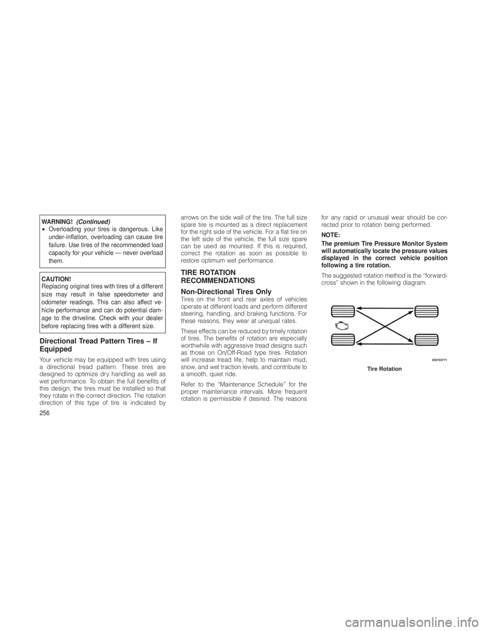
The suggested rotation method is the “forward-
cross” shown in the following diagram.
Tire Rotation
256
Page 261 of 380

TIRE PRESSURE MONITOR SYSTEM
(TPMS)
The Tire Pressure Monitoring System (TPMS)
will warn the driver of a low tire pressure based
on the vehicle recommended cold tire pressure.
The tire pressure will vary with temperature by
about 1 psi (7 kPa) for every 12°F (6.5°C). This
means that when the outside temperature de-
creases, the tire pressure will decrease. Tire
pressure should always be set based on cold
inflation tire pressure. This is defined as the tire
pressure after the vehicle has not been driven
for at least three hours, or driven less than
1 mile (1.6 km) after a three-hour period.Refer
to “Tires – General Information” in “Starting
and Operating” for information on how to
properly inflate the vehicle’s tires. The tire
pressure will also increase as the vehicle is
driven - this is normal and there should be no
adjustment for this increased pressure.
The TPMS will warn the driver of a low tire
pressure if the tire pressure falls below the low
pressure warning threshold for any reason,
including low temperature effects, or natural
pressure loss through the tire. The TPMS will continue to warn the driver of low
tire pressure as long as the condition exists,
and will not turn off until the tire pressure is at or
above recommended cold tire pressure. Once
the “TPM Telltale Light” and the “TIRE LOW
PRESSURE” message appears, the tire pres-
sure must be increased to the recommended
cold tire pressure in order for the ”TPM Telltale
Light” and the “TIRE LOW PRESSURE” mes-
sage to be turned off. The system will automati-
cally update and the “TPM Telltale Light” and
the “TIRE LOW PRESSURE” message will turn
off once the updated tire pressures have been
received. The vehicle may need to be driven for
up to 20 minutes above 15 mph (24 km/h) to
receive this information.
For example, your vehicle has a recommended
cold (parked for more than three hours) tire
pressure of 33 psi (227 kPa). If the ambient
temperature is 68°F (20°C) and the measured
tire pressure is 28 psi (193 kPa), a temperature
drop to 20°F (-7°C) will decrease the tire pres-
sure to approximately 24 psi (165 kPa). This tire
pressure is sufficiently low enough to display
the “TPM Telltale Light” and the “TIRE LOW
PRESSURE” message. Driving the vehicle maycause the tire pressure to rise to approximately
28 psi (193 kPa), but the “TPM Telltale Light”
and the “TIRE LOW PRESSURE” message will
still display. In this situation, the “TPM Telltale
Light” and the “TIRE LOW PRESSURE” mes-
sage will turn OFF only after the tires have been
inflated to the vehicle’s recommended cold tire
pressure value.
CAUTION!
•
The TPMS has been optimized for the
original equipment tires and wheels. TPMS
pressures have been established for the
tire size equipped on your vehicle. Unde-
sirable system operation or sensor damage
may result when using replacement equip-
ment that is not of the same size, type,
and/or style. Aftermarket wheels can cause
sensor damage. Do not use aftermarket tire
sealants or balance beads if your vehicle is
equipped with a TPMS, as damage to the
sensors may result.
(Continued)
257
Page 262 of 380
CAUTION!(Continued)
• After inspecting or adjusting the tire pres-
sure always reinstall the valve stem cap.
This will prevent moisture and dirt from
entering the valve stem, which could dam-
age the Tire Pressure Monitoring Sensor.
NOTE:
• The TPMS is not intended to replace nor-
mal tire care and maintenance, or to pro-
vide warning of a tire failure or condition.
• The TPMS should not be used as a tire
pressure gauge while adjusting your tire
pressure.
• Driving on a significantly under-inflated
tire causes the tire to overheat and can
lead to tire failure. Under-inflation also
reduces fuel efficiency and tire tread life,
and may affect the vehicle’s handling and
stopping ability.
• The TPMS is not a substitute for proper
tire maintenance, and it is the driver’s
responsibility to maintain correct tire
pressure using an accurate tire gauge,
even if under-inflation has not reached the level to trigger the display of the “TPM
Telltale Light” and the “TIRE LOW PRES-
SURE” message.
• Seasonal temperature changes will affect
tire pressure, and the TPMS will monitor
the actual tire pressure in the tire.
Base SystemThe Tire Pressure Monitor System (TPMS) uses
wireless technology with wheel rim-mounted
electronic sensors to monitor tire pressure lev-
els. Sensors, mounted to each wheel as part of
the valve stem, transmit tire pressure readings
to the Receiver Module.
NOTE:
It is particularly important, for you to regu-
larly check the tire pressure in all of your
tires, and to maintain the proper pressure.
The TPMS consists of the following compo-
nents:
•Receiver Module
• Four Tire Pressure Monitoring Sensors
• Tire Pressure Monitoring Telltale Light A low spare tire will not cause the “Tire Pressure
Monitoring Telltale Light” to illuminate, a warn-
ing message to appear, or the chime to sound.
The “Tire Pressure Monitoring Telltale
Light” will illuminate in the instrument
cluster, a “TIRE LOW PRESSURE”
message will display in the instrument
cluster for 5 seconds, and an audible chime will
be activated, when one or more of the four
active road tire pressures are low. Should this
occur, you should stop as soon as possible,
check the inflation pressure of each tire on your
vehicle, and inflate each tire to the vehicle’s
recommended cold placard pressure value.
The system will automatically update and the
“Tire Pressure Monitoring Telltale Light” will
extinguish, once the updated tire pressures
have been received. The vehicle may need to
be driven for up to 20 minutes above 15 mph
(24 km/h) to receive this information.
The “Tire Pressure Monitoring Telltale Light” will
flash on and off for 75 seconds, and remain on
solid when a system fault is detected. In addi-
tion, a “SERVICE TPM SYSTEM” message may
be displayed for approximately 5 seconds
when a system fault is detected, and a chime
258
Page 263 of 380
will sound. If the ignition switch is cycled, this
sequence will repeat, providing the system
fault still exists. The “Tire Pressure Monitoring
Telltale Light” will turn off when the fault condi-
tion no longer exists. A system fault can occur
by any of the following:
1. Jamming due to electronic devices or driv-
ing next to facilities emitting the same Radio
Frequencies as the TPM sensors.
2. Installing some form of aftermarket window
tinting that affects radio wave signals.
3. Lots of snow or ice around the wheels or
wheel housings.
4. Using tire chains on the vehicle.
5. Using wheels/tires not equipped with TPM
sensors.
NOTE:
There is no tire pressure monitoring sensor
in the spare tire. The TPMS will not be able to
monitor the tire pressure. If you install the
spare tire, in place of a road tire, that has a
pressure below the low-pressure warning
limit, upon the next ignition switch cycle, a
chime will sound, a “TIRE LOW PRESSURE”message will be displayed in the instrument
cluster, and the “Tire Pressure Monitoring
Telltale Light” will turn ON. After driving the
vehicle for up to 20 minutes above 15 mph
(25 km/h), the “Tire Pressure Monitoring
Telltale Light” will flash on and off for
75 seconds and then remain on solid. In
addition, a “SERVICE TPM SYSTEM” mes-
sage will be displayed. For each subsequent
ignition switch cycle, a chime will sound, a
“SERVICE TPM SYSTEM” message will be
displayed, and the “Tire Pressure Monitor-
ing Telltale Light” will flash on and off for
75 seconds and then remain on solid. Once
you repair or replace the original road tire,
and reinstall it on the vehicle in place of the
spare tire, the TPMS will update automati-
cally and the “Tire Pressure Monitoring Tell-
tale Light” will turn OFF, as long as no tire
pressure is below the low-pressure warning
limit in any of the four active road tires. The
vehicle may need to be driven for up to
20 minutes above 15 mph (24 km/h) in order
for the TPMS to receive this information.Premium System – If EquippedThe Tire Pressure Monitor System (TPMS) uses
wireless technology with wheel rim-mounted
electronic sensors to monitor tire pressure lev-
els. Sensors, mounted to each wheel as part of
the valve stem, transmit tire pressure readings
to the Receiver Module.
NOTE:
It is particularly important, for you to regu-
larly check the tire pressure in all of your
tires and to maintain the proper pressure.
The Tire Pressure Monitor System (TPMS) con-
sists of the following components:
•
Receiver Module
• Four Tire Pressure Monitoring Sensors
• Tire Pressure Monitoring Telltale Light
• Various Tire Pressure Monitoring System
Messages, which display in the Electronic
Vehicle Information Center (EVIC), and a
graphic displaying tire pressures
259