center console JEEP GRAND CHEROKEE 2013 Owner handbook (in English)
[x] Cancel search | Manufacturer: JEEP, Model Year: 2013, Model line: GRAND CHEROKEE, Model: JEEP GRAND CHEROKEE 2013Pages: 408, PDF Size: 3.21 MB
Page 33 of 408
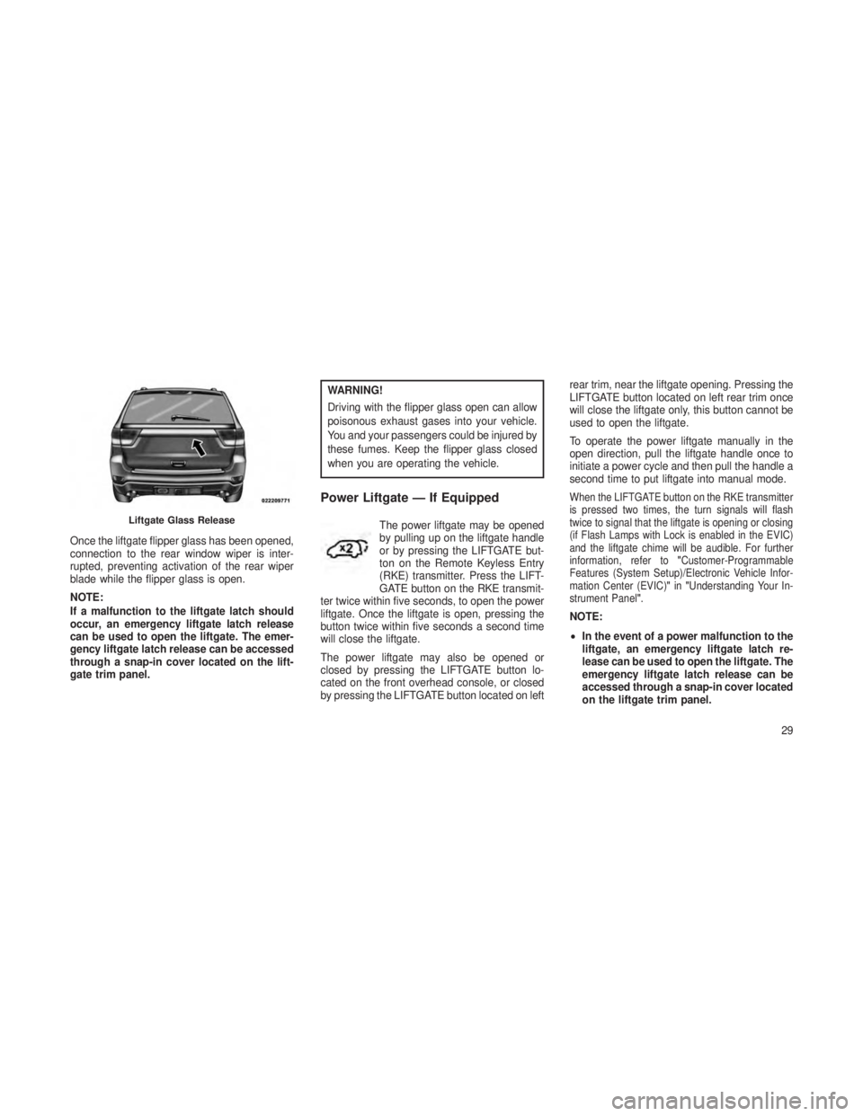
Once the liftgate flipper glass has been opened,
connection to the rear window wiper is inter-
rupted, preventing activation of the rear wiper
blade while the flipper glass is open.
NOTE:
If a malfunction to the liftgate latch should
occur, an emergency liftgate latch release
can be used to open the liftgate. The emer-
gency liftgate latch release can be accessed
through a snap-in cover located on the lift-
gate trim panel.
WARNING!
Driving with the flipper glass open can allow
poisonous exhaust gases into your vehicle.
You and your passengers could be injured by
these fumes. Keep the flipper glass closed
when you are operating the vehicle.
Power Liftgate — If Equipped
The power liftgate may be opened
by pulling up on the liftgate handle
or by pressing the LIFTGATE but-
ton on the Remote Keyless Entry
(RKE) transmitter. Press the LIFT-
GATE button on the RKE transmit-
ter twice within five seconds, to open the power
liftgate. Once the liftgate is open, pressing the
button twice within five seconds a second time
will close the liftgate.
The power liftgate may also be opened or
closed by pressing the LIFTGATE button lo-
cated on the front overhead console, or closed
by pressing the LIFTGATE button located on left rear trim, near the liftgate opening. Pressing the
LIFTGATE button located on left rear trim once
will close the liftgate only, this button cannot be
used to open the liftgate.
To operate the power liftgate manually in the
open direction, pull the liftgate handle once to
initiate a power cycle and then pull the handle a
second time to put liftgate into manual mode.
When the LIFTGATE button on the RKE transmitter
is pressed two times, the turn signals will flash
twice to signal that the liftgate is opening or closing
(if Flash Lamps with Lock is enabled in the EVIC)
and the liftgate chime will be audible. For further
information, refer to
"Customer-Programmable
Features (System Setup)/Electronic Vehicle Infor-
mation Center (EVIC) "in "Understanding Your In-
strument Panel".
NOTE:
• In the event of a power malfunction to the
liftgate, an emergency liftgate latch re-
lease can be used to open the liftgate. The
emergency liftgate latch release can be
accessed through a snap-in cover located
on the liftgate trim panel.
Liftgate Glass Release
29
Page 72 of 408
•COMMANDVIEW® SUNROOF WITH POWER SHADE — IF
EQUIPPED ...................................144
•Opening Sunroof — Express ...................... .144
• Opening Sunroof — Manual Mode ....................144
• Closing Sunroof — Express ........................144
• Closing Sunroof — Manual Mode .....................145
• Opening Power Shade — Express ....................145
• Opening Power Shade — Manual Mode .................145
• Closing Power Shade — Express .....................145
• Closing Power Shade — Manual Mode .................145
• Pinch Protect Feature .......................... .145
• Wind Buffeting .............................. .145
• Sunroof Maintenance ........................... .146
• Ignition OFF Operation .......................... .146
• Sunroof Fully Closed ........................... .146
•ELECTRICAL POWER OUTLETS .....................146
• CUPHOLDERS .................................149
• STORAGE ....................................149
•Glove Compartment ............................ .149
• Door Storage ................................ .150
• Center Console .............................. .150
•CARGO AREA FEATURES .........................151•Rechargeable Flashlight ......................... .151
• Cargo Storage Bins ........................... .151
• Retractable Cargo Area Cover — If Equipped .............152
• Rear Cargo Tie-Downs .......................... .153
68
Page 101 of 408
Vehicles Equipped with Remote Start
On models that are equipped with remote start,
the driver’s heated seat and heated steering
wheel can be programmed to come on during a
remote start. Refer to “Remote Starting System —
If Equipped” in “Things To Know Before Starting
Your Vehicle” for further information.
Front Heated Seats
There are two heated seat switches that allow
the driver and passenger to operate the seats
independently. The controls for each heater are
located near the bottom center of the instrument
panel (below the climate controls).
You can choose from HIGH, LOW or OFF heat
settings. Amber indicator lights in each switch
indicate the level of heat in use. Two indicator
lights will illuminate for HIGH, one for LOW and
none for OFF.
Press the switch once to select
HIGH-level heating. Press the switch
a second time to select LOW-level
heating. Press the switch a third time
to shut the heating elements OFF.
NOTE:
Once a heat setting is selected, heat will be
felt within two to five minutes.
When the HIGH-level setting is selected, the
heater will provide a boosted heat level during
the first four minutes of operation. Then, the
heat output will drop to the normal HIGH-level. If
the HIGH-level setting is selected, the system
will automatically switch to LOW-level after ap-
proximately 60 minutes of continuous opera-
tion. At that time, the number of illuminated
LEDs changes from two to one, indicating the
change. The LOW-level setting will turn OFF
automatically after approximately 45 minutes.
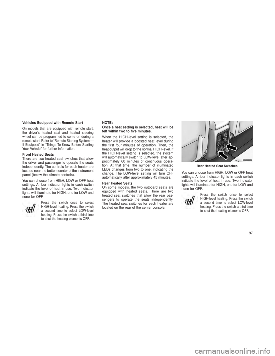
Rear Heated Seats
On some models, the two outboard seats are
equipped with heated seats. There are two
heated seat switches that allow the rear pas-
sengers to operate the seats independently.
The heated seat switches for each heater are
located on the rear of the center console.You can choose from HIGH, LOW or OFF heat
settings. Amber indicator lights in each switch
indicate the level of heat in use. Two indicator
lights will illuminate for HIGH, one for LOW and
none for OFF.
Press the switch once to select
HIGH-level heating. Press the switch
a second time to select LOW-level
heating. Press the switch a third time
to shut the heating elements OFF.
Rear Heated Seat Switches
97
Page 115 of 408
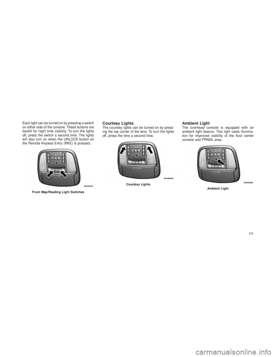
Each light can be turned on by pressing a switch
on either side of the console. These buttons are
backlit for night time visibility. To turn the lights
off, press the switch a second time. The lights
will also turn on when the UNLOCK button on
the Remote Keyless Entry (RKE) is pressed.Courtesy LightsThe courtesy lights can be turned on by press-
ing the top corner of the lens. To turn the lights
off, press the lens a second time.Ambient LightThe overhead console is equipped with an
ambient light feature. This light casts illumina-
tion for improved visibility of the floor center
console and PRNDL area.
Front Map/Reading Light Switches
Courtesy LightsAmbient Light
111
Page 151 of 408
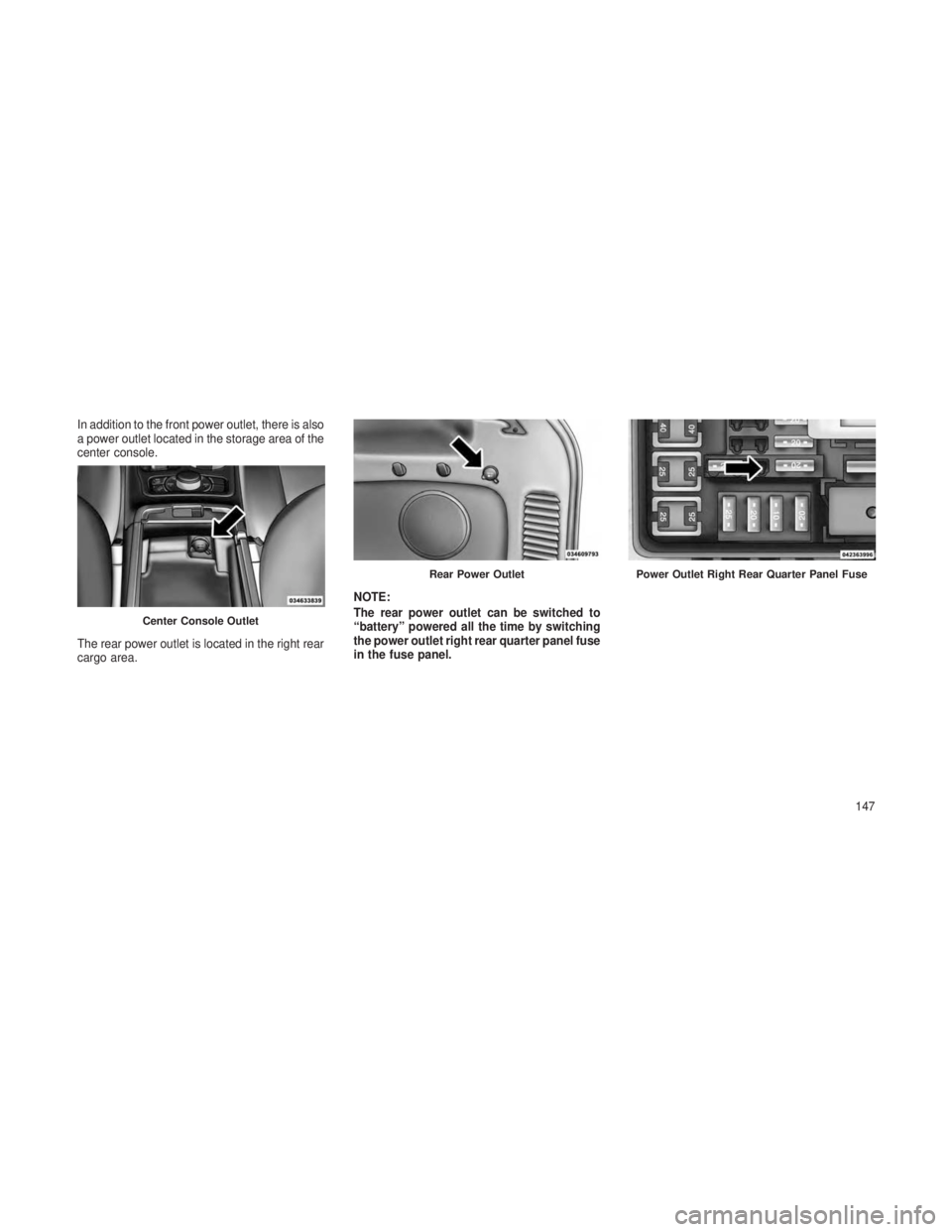
In addition to the front power outlet, there is also
a power outlet located in the storage area of the
center console.
The rear power outlet is located in the right rear
cargo area.NOTE:
The rear power outlet can be switched to
“battery” powered all the time by switching
the power outlet right rear quarter panel fuse
in the fuse panel.
Center Console Outlet
Rear Power OutletPower Outlet Right Rear Quarter Panel Fuse
147
Page 153 of 408
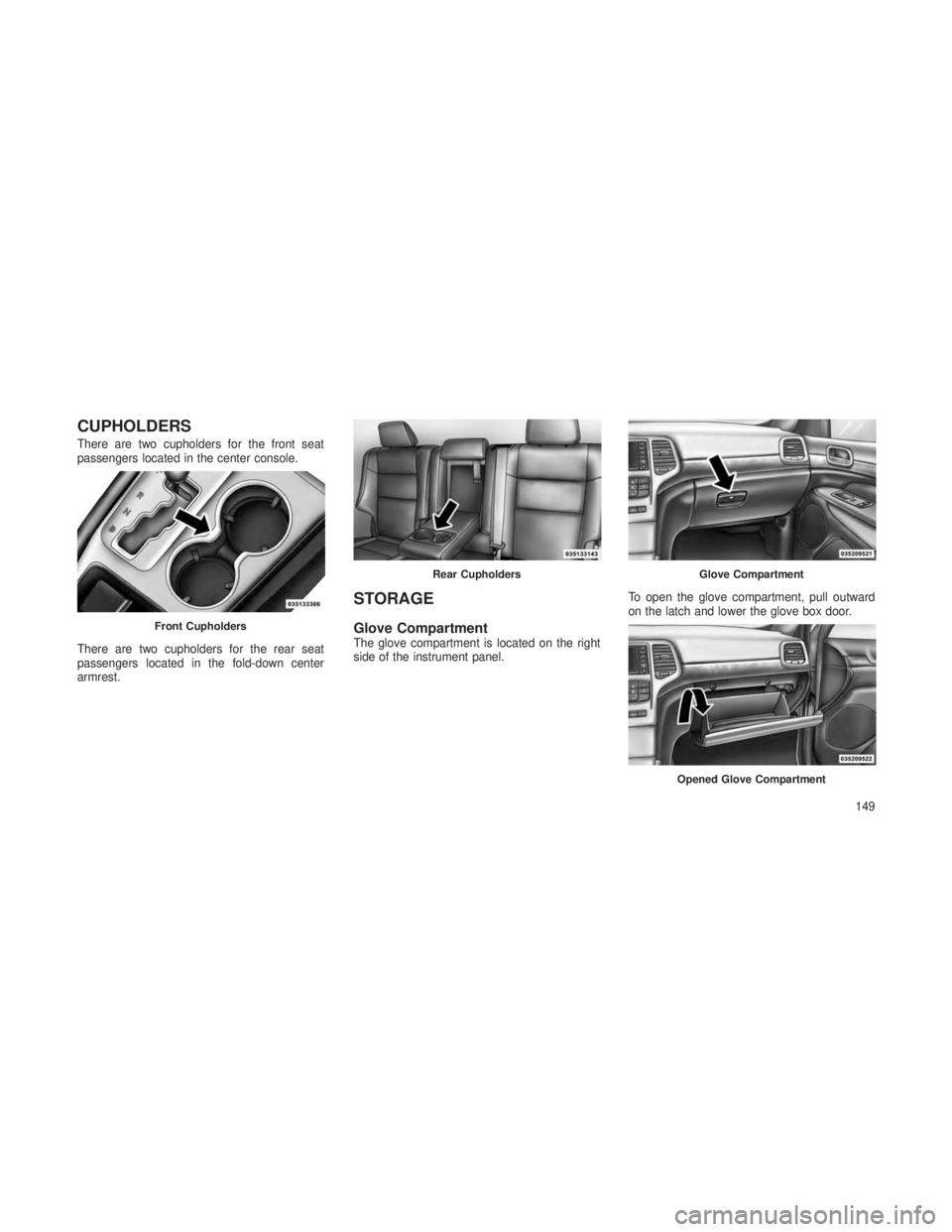
CUPHOLDERS
There are two cupholders for the front seat
passengers located in the center console.
There are two cupholders for the rear seat
passengers located in the fold-down center
armrest.
STORAGE
Glove CompartmentThe glove compartment is located on the right
side of the instrument panel.To open the glove compartment, pull outward
on the latch and lower the glove box door.
Front Cupholders
Rear CupholdersGlove Compartment
Opened Glove Compartment
149
Page 154 of 408
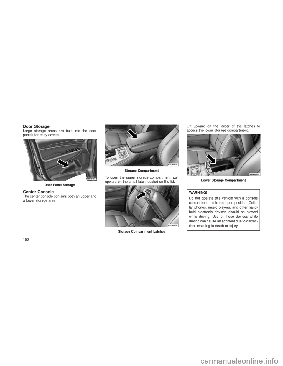
Door StorageLarge storage areas are built into the door
panels for easy access.
Center ConsoleThe center console contains both an upper and
a lower storage area.To open the upper storage compartment, pull
upward on the small latch located on the lid.Lift upward on the larger of the latches to
access the lower storage compartment.WARNING!
Do not operate this vehicle with a console
compartment lid in the open position. Cellu-
lar phones, music players, and other hand-
held electronic devices should be stowed
while driving. Use of these devices while
driving can cause an accident due to distrac-
tion, resulting in death or injury.
Door Panel Storage
Storage Compartment
Storage Compartment Latches
Lower Storage Compartment
150
Page 193 of 408
iPod®/USB/MP3 CONTROL —
IF EQUIPPED
This feature allows an iPod® or external USB
device to be plugged into the USB port, located
in the center console or glove compartment.
iPod® control supports Mini, 4G, Photo, Nano,
5G iPod® and iPhone® devices. Some iPod®
software versions may not fully support the
iPod® control features. Please visit Apple’s
website for software updates.
NOTE:
•If the radio has a USB port, refer to the
appropriate Uconnect® Multimedia radio
User’s Manual for iPod® or external USB
device support capability.
• Connecting an iPod® or consumer elec-
tronic audio device to the AUX port lo-
cated in the radio faceplate, plays media,
but does not use the iPod® /MP3 control
feature to control the connected device.
Connecting The iPod® Or External
USB Device
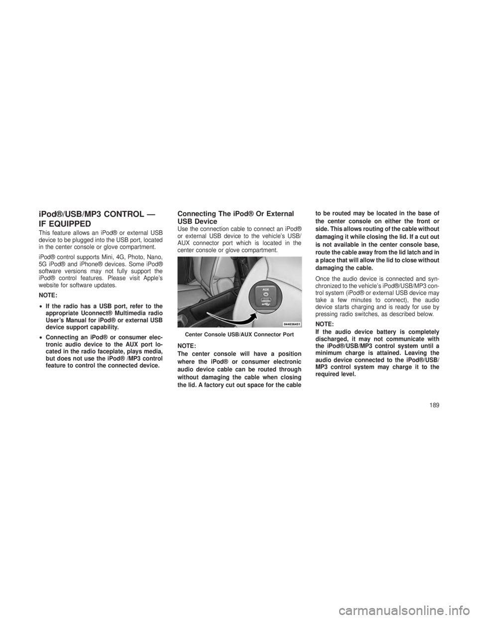
Use the connection cable to connect an iPod®
or external USB device to the vehicle’s USB/
AUX connector port which is located in the
center console or glove compartment.
NOTE:
The center console will have a position
where the iPod® or consumer electronic
audio device cable can be routed through
without damaging the cable when closing
the lid. A factory cut out space for the cable to be routed may be located in the base of
the center console on either the front or
side. This allows routing of the cable without
damaging it while closing the lid. If a cut out
is not available in the center console base,
route the cable away from the lid latch and in
a place that will allow the lid to close without
damaging the cable.
Once the audio device is connected and syn-
chronized to the vehicle’s iPod®/USB/MP3 con-
trol system (iPod® or external USB device may
take a few minutes to connect), the audio
device starts charging and is ready for use by
pressing radio switches, as described below.
NOTE:
If the audio device battery is completely
discharged, it may not communicate with
the iPod®/USB/MP3 control system until a
minimum charge is attained. Leaving the
audio device connected to the iPod®/USB/
MP3 control system may charge it to the
required level.
Center Console USB/AUX Connector Port
189
Page 211 of 408
If your vehicle is not equipped with the separate
DVD player, the following events in the Radio
will cause the screen(s) to automatically switch
to Radio Disc mode.
•Loading a disc in the radio CD/DVD player
• AM/FM band selection via Radio
Auxiliary InputsFor each video screen there is an auxiliary (Aux
jack) device input which is used to connect exter-
nal audio/video sources to the VES™. Examples
of devices that can be connected to the Aux inputs
include portable music players, video cameras,
VCR’s, game systems, and other devices with
audio and/or video outputs. The Aux jacks are
typically located on the back of the center console
or on one of the vehicles side panels in the rear
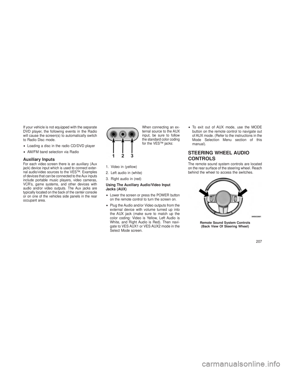
occupant area. When connecting an ex-
ternal source to the AUX
input, be sure to follow
the standard color coding
for the VES™ jacks:1. Video in (yellow)
2. Left audio in (white)
3. Right audio in (red)
Using The Auxiliary Audio/Video Input
Jacks (AUX)
•
Lower the screen or press the POWER button
on the remote control to turn the screen on.
•
Plug the Audio and/or Video outputs from the
external device with volume turned up into
the AUX jack (make sure to match up the
color coding: Video is Yellow, Left Audio is
White, and Right Audio is Red). Then navi-
gate to VES AUX1 or VES AUX2 mode in the
Select Mode screen. •
To exit out of AUX mode, use the MODE
button on the remote control to navigate out
of AUX mode. (Refer to the instructions in the
Mode Selection Menu section of this
manual).
STEERING WHEEL AUDIO
CONTROLS
The remote sound system controls are located
on the rear surface of the steering wheel. Reach
behind the wheel to access the switches.
Remote Sound System Controls
(Back View Of Steering Wheel)
207
Page 399 of 408
Center High Mounted Stop Light......339
Chains, Tire ................. .265
Checking Your Vehicle For Safety ......59
Checks, Safety .................59
Child Restraint ........50, 53, 54, 55, 56
Child Restraint Tether Anchors ......54, 55
Child Safety Locks ...............23
Clean Air Gasoline ..............274
Cleaning Wheels ................. .329
Climate Control ................209
Cold Weather Operation ...........222
Compact Disc (CD) Maintenance ......208
Compact Spare Tire .............262
Compass ...................182
Compass Calibration .............184
Compass Variance ..............182
Computer, Trip/Travel ............179
Connector UCI ................... .189
Universal Consumer Interface (UCI) . .189
Conserving Fuel ...............178
Console, Overhead ..............140
Coolant Pressure Cap (Radiator Cap) . . .323
Cooling System ................321
Adding Coolant (Antifreeze) ......322
Coolant Capacity ............340 Coolant Level
..............323
Disposal of Used Coolant ........323
Drain, Flush, and Refill .........321
Inspection .............321, 323
Points to Remember ..........324
Pressure Cap ..............323
Radiator Cap ...............323
Selection of Coolant
(Antifreeze) .............322, 340
Cruise Control (Speed Control) .......119
Cupholders ................. .149
Customer Assistance .............372
Data Recorder, Event .............49
Daytime Running Lights..........
.108
Defroster, Rear Window ...........154
Defroster, Windshield ..........60, 212
Diesel Fuel ................. .275
Diesel Fuel Requirements ..........275
Dipsticks Automatic Transmission .........327
Oil (Engine) ...............313
Power Steering .............250
Disabled Vehicle Towing ...........304
Disposal Antifreeze (Engine Coolant) ......323
Door Locks ...................21 Door Locks, Automatic
............22
Driving .................... .244
Off-Pavement ..............245
Off-Road .................245
Driving to Achieve Maximum Fuel Economy ................. .178
Electrical Outlet, Auxiliary (Power Outlet) ...............146
Electric Rear Window Defrost ........154
Electric Remote Mirrors ............71
Electronic Brake Control System ......252
Brake Assist System ..........252
Electronic Roll Mitigation (ERM) ......253
Electronic Speed Control (Cruise Control) ...........117,119
Electronic Stability Control (ESC) ......253
Electronic Vehicle Information Center (EVIC) ............164, 168
Emergency, In Case of Freeing Vehicle When Stuck ......302
Hazard Warning Flasher ........294
Jump Starting ..............300
Engine Air Cleaner ................315
Break-In Recommendations .......59
Compartment .........309, 310, 311
395