ECO mode JEEP RENEGADE 2023 User Guide
[x] Cancel search | Manufacturer: JEEP, Model Year: 2023, Model line: RENEGADE, Model: JEEP RENEGADE 2023Pages: 364, PDF Size: 18.65 MB
Page 44 of 364
42 GETTING TO KNOW YOUR VEHICLE
WINDSHIELD WIPER OPERATION
Rotate the windshield wiper knob to one of the two
detent positions for intermittent settings, the third
detent for low wiper operation and the fourth for
high wiper operation.
Windshield Washer Operation
To use the washer, pull the lever toward you and
hold w h
ile spray is desired. If the lever is pulled
while in the intermittent setting, the wipers will turn
on and operate for several wipe cycles after the
lever is released, and then resume the intermittent
interval previously selected.
If the lever is pulled while the wipers are in the off
positi on
, the wipers will operate for several wipe
cycles, then turn off. Mist
Use this feature when weather conditions make
occasi
on
al usage of the wipers necessary. Push
the lever upward to the MIST position and release
for a single wiping cycle.
NOTE:
The Mist feature does not activate the washer
pump;
therefore, no washer fluid will be sprayed on
the windshield. The wash function must be used in
order to spray the windshield with washer fluid.
For information on wiper care and replacement,
see Ú p
age 297 .
RAIN SENSING WIPERS — IF EQUIPPED
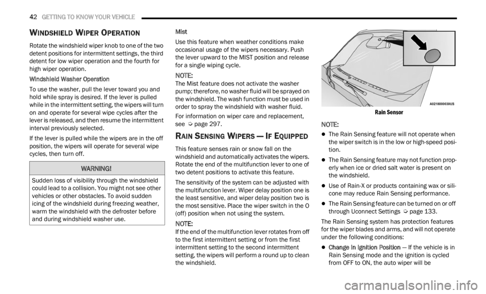
This feature senses rain or snow fall on the
windshield and automatically activates the wipers.
Rotate the end of the multifunction lever to one of
two detent positions to activate this feature.
The sensitivity of the system can be adjusted with
the mu
ltifunction lever. Wiper delay position one is
the least sensitive, and wiper delay position two is
the most sensitive. Place the wiper switch in the O
(off) position when not using the system.
NOTE:
If the end of the multifunction lever rotates from off
to the
first intermittent setting or from the first
intermittent setting to the second intermittent
setting, the wipers will perform a round up to clean
the windshield.
Rain Sensor
NOTE:
The Rain Sensing feature will not operate when
the wiper switch is in the low or high-speed posi
-
tion.
The Rain Sensing feature may not function prop -
erly when ice or dried salt water is present on
t h e
w
i
ndshield.
Use of Rain-X or products containing wax or sili-
cone may reduce Rain Sensing performance.
The Rain Sensing feature can be turned on or off
through Uconnect Settings Ú page 133.
The Rain Sensing system has protection features
f or the
wiper blades and arms, and will not operate
under the following conditions:
Change In Ignition Position — If the vehicle is in
Rain Sensing mode and the ignition is cycled
from OFF to ON, the auto wiper will be
WARNING!
Sudden loss of visibility through the windshield
could lead to a collision. You might not see other
vehicles or other obstacles. To avoid sudden
icing of the windshield during freezing weather,
warm the windshield with the defroster before
and during windshield washer use.
Page 45 of 364
GETTING TO KNOW YOUR VEHICLE 43
suppressed until vehicle speed is greater than
3 mph (5 km/h), or the wiper switch is moved
out of a
nd back into the Intermittent wipe posi -
tion.
Transmission In NEUTRAL Position — The Rain
Sensing system will not operate if the NEUTRAL
gear is selected at speeds of 3 mph (5 km/h) or
less u
nless the wiper switch is moved or the
gear selector is moved out of NEUTRAL.
Remote Start Mode Inhibit — On vehicles
equipped with the Remote Start system, Rain
Sensing wipers are not operational when the
vehicle is in the Remote Start mode. Once the
operator is in the vehicle and has placed the
ignition switch in the ON/RUN position, Rain
Sensing wiper operation can resume, if it has
been selected, and no other inhibit conditions
(mentioned previously) exist.
REAR WINDOW WIPER/WASHER
The rear wiper/washer controls are located on the
windshield wiper/washer lever on the right side of
the steering column. The rear wiper/washer is
operated by rotating a switch, located at the
middle of the lever.
NOTE:
If the front wiper is moving and the vehicle is
shift e
d in REVERSE, the rear wiper will perform one
round up to clean the rear window. Rotate the center portion of the lever
upward to the first detent for intermittent
operat
i
on and to the second detent for
continuous rear wiper operation. If the
front wiper is set to Automatic mode (on the wiper
lever as well as enabled through Uconnect
Settings), placing the rear wiper in an intermittent
position will cause the front and rear wipers to sync
up. Turning the front wipers off will cause the rear
wipers to also stop.
To use the washer, push the lever
forward and hold while spray is desired. If
the l e
ver is pushed while the wiper is in
the off position, the wiper will operate for
several wipe cycles, then turn off.
If the lever is pushed while in the intermittent
settin
g, the wiper will turn on and operate for
several wipe cycles after the end of the lever is
released, and then resume the intermittent
interval previously selected.
NOTE:
As a protective measure, the pump will stop if the
switc h
is held for more than 30 seconds. Once the
lever is released, the pump will resume normal
operation.
WINDSHIELD WIPER DE-ICER —
I
F EQUIPPED
Your vehicle may be equipped with a Windshield
Wiper De-Icer feature that may be activated under
the following conditions:
Activation By Front Defrost — The Windshield
Wiper De-Icer will be activated automatically in
the case of a cold weather manual start with full
front defrost, and the ambient temperature is
below 40°F (4.4°C).
CAUTION!
Failure to follow these cautions can cause
damage to the heating elements:
Use care when washing the inside of the rear
window. Do not use abrasive window cleaners
on the interior surface of the window. Use a
soft cloth and a mild washing solution, wiping
parallel to the heating elements. Labels can
be peeled off after soaking with warm water.
Do not use scrapers, sharp instruments, or
abrasive window cleaners on the interior
surface of the window.
Keep all objects a safe distance from the
window.
2
Page 47 of 364
GETTING TO KNOW YOUR VEHICLE 45
(button on the touchscreen grayed out) if
conditions exist that could create fogging on the
inside of the windshield. The A/C can be
deselected manually without disturbing the mode
control selection. Continuous use of the
Recirculation mode may make the inside air stuffy
and window fogging may occur. Extended use of
this mode is not recommended. Recirculation
mode may automatically adjust to optimize
customer experience for warming, cooling,
dehumidification, etc.
In cold weather, use of Recirculation mode may
lead t
o excessive window fogging. The
Recirculation feature may be unavailable if
conditions exist that could create fogging on the
inside of the windshield.
AUTO Button
Press and release this button on the
touchscreen, or push the button on the
facep l
ate, to change the current setting.
The AUTO indicator illuminates when
AUTO is on. This feature automatically controls the
interior cabin temperature by adjusting distribution
and amount of airflow. Air Conditioning (A/C) may
be active during AUTO operation to improve
performance. Toggling this function will cause the
system to switch between manual override mode
and automatic modes Ú page 47.
Front Defrost Button
Press and release the touchscreen
button, or push and release the button
on the
faceplate, to change the current
airflow setting to Defrost mode. The Front
Defrost indicator illuminates when Front Defrost is
on. Air comes from the windshield and side window
demist outlets. When the defrost button is
selected, the blower level may increase. Use
Defrost mode with maximum temperature settings
for best windshield and side window defrosting
and defogging. When toggling the front defrost
mode button, the Climate Control system will
return to the previous setting.
Rear Defrost Button
Press and release the button on the
touchscreen, or push and release the
button
on the faceplate, to turn on the
rear window defroster and the heated
outside mirrors (if equipped). The Rear Defrost
indicator illuminates when the rear window
defroster is on. The rear window defroster
automatically turns off after 20 minutes.Driver And Passenger Up And Down
Buttons
These buttons provide the driver and passenger
with independent temperature control.
Push the red button on the faceplate or
touchscreen or press and slide the
temper
ature bar towards the red arrow
button on the touchscreen for warmer
temperature settings.
CAUTION!
Failure to follow these cautions can cause
damage to the heating elements:
Use care when washing the inside of the rear
window. Do not use abrasive window cleaners
on the interior surface of the window. Use a
soft cloth and a mild washing solution, wiping
parallel to the heating elements. Labels can
be peeled off after soaking with warm water.
Do not use scrapers, sharp instruments, or
abrasive window cleaners on the interior
surface of the window.
Keep all objects a safe distance from the
window.
2
Page 49 of 364

GETTING TO KNOW YOUR VEHICLE 47
AUTOMATIC TEMPERATURE CONTROL
(ATC)
Automatic Operation
1. Push the AUTO button on the faceplate, or the
AUTO button on the touchscreen on the
Automatic Temperature Control (ATC) Panel.
2. Adjust the temperature you would like the syste
m to maintain, by adjusting the driver,
and passenger temperatures. Once the
desired temperature is displayed, the system
will achieve and automatically maintain that
comfort level.
3. When the system is set up for your comfort level
, it is not necessary to change the
settings. You will experience the greatest
efficiency by simply allowing the system to
function automatically.
NOTE:
It is not necessary to move the temperature
settings. The system automatically adjusts the
temperature, mode, and fan speed to provide
comfort as quickly as possible.
The temperature can be displayed in U.S. or
Metric units by selecting the U.S./Metric
customer programmable feature within
Uconnect Settings. To provide you with maximum comfort in the
automa
t
ic mode, during cold start-ups, the blower
fan will remain on low until the engine warms up.
The fan will engage immediately if the Defrost
mode is selected, or by changing the front blower
knob setting.
Manual Operation Override
This system offers a full complement of manual
override features. The AUTO symbol in the front
ATC display will be turned off when the system is
being used in the manual mode.
CLIMATE VOICE COMMANDS
Adjust vehicle temperatures hands-free and keep
everyone comfortable while you keep moving
ahead.
Push the VR button on the steering wheel. After the
beep,
say one of the following commands:
“Set the driver temperature to 70 degrees ”
“Set the passenger temperature to 70 degrees ”
Did You Know:
V oi
ce
Command for Climate may
only be used to adjust the interior temperature of
your vehicle. Voice Command will not adjust the
heated seats or steering wheel if equipped.
OPERATING TIPS
Refer to the chart at the end of this section for
suggested control settings for various weather
conditions.
Summer Operation
The engine cooling system must be protected with
a high-quality antifreeze coolant to provide proper
corrosion protection and to protect against engine
overheating. OAT coolant (conforming to
MS.90032) is recommended.
Winter Operation
To ensure the best possible heater and defroster
performance, make sure the engine cooling
system is functioning properly and the proper
amount, type, and concentration of coolant is
used. Use of the Air Recirculation mode during
Winter months is not recommended, because it
may cause window fogging.
Vacation/Storage
For information on maintaining the Climate Control
system when the vehicle is being stored for an
extended period of time, see Ú page 338.
Window Fogging
Vehicle windows tend to fog on the inside in mild,
rainy, and/or humid weather. To clear the
windows, select Defrost or Mix mode and increase
the front blower speed. Do not use the
Recirculation mode without A/C for long periods,
as fogging may occur.
Outside Air Intake
Make sure the air intake, located directly in front of
the windshield, is free of obstructions, such as
2
Page 52 of 364
50 GETTING TO KNOW YOUR VEHICLE
USB/AUX CONTROL
This feature allows an external device to be
plugged into the USB port or AUX Jack.
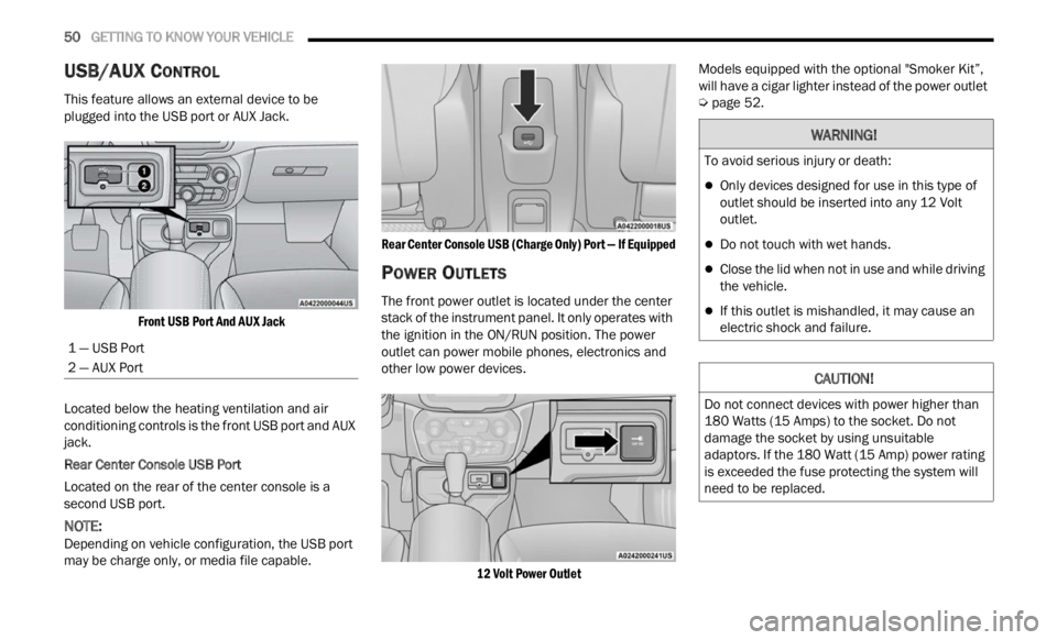
Front USB Port And AUX Jack
Located below the heating ventilation and air
condit i
oning controls is the front USB port and AUX
jack.
Rear Center Console USB Port
Located on the rear of the center console is a
s econd
USB port.
NOTE:
Depending on vehicle configuration, the USB port
may b e
charge only, or media file capable.
Rear Center Console USB (Charge Only) Port — If Equipped
POWER OUTLETS
The front power outlet is located under the center
stack of the instrument panel. It only operates with
the ignition in the ON/RUN position. The power
outlet can power mobile phones, electronics and
other low power devices.
12 Volt Power Outlet
Models equipped with the optional "Smoker Kit”,
will h
ave a cigar lighter instead of the power outlet
Ú page 52.
1 — USB Port
2 — AUX Port
WARNING!
To avoid serious injury or death:
Only devices designed for use in this type of
outlet should be inserted into any 12 Volt
outlet.
Do not touch with wet hands.
Close the lid when not in use and while driving
the vehicle.
If this outlet is mishandled, it may cause an
electric shock and failure.
CAUTION!
Do not connect devices with power higher than
180 Watts (15 Amps) to the socket. Do not
damage the socket by using unsuitable
adaptors. If the 180 Watt (15 Amp) power rating
is exceeded the fuse protecting the system will
need to be replaced.
Page 69 of 364

GETTING TO KNOW YOUR INSTRUMENT PANEL 67
Audio
Push and release the up or down arrow
button until the Audio menu title is displayed in the
instr u
ment cluster display.
Stored Messages
Push and release the up or down arrow
button until the Messages Menu Icon is highlighted
in th e
instrument cluster display. This feature
shows the number of stored warning messages.
Pushing the left
or right arrow button will
all ow
you to scroll through the stored messages.
Screen Setup
This menu item allows you to change the position
of the information on the display.
Display Gears (Vehicles With Reconfigurable
Multi-
Functional Display And Automatic
Transmission)
By selecting this item, you can select the display
mode, t
he particulars relating to the automatic
transmission, and choose between the following
options:
“Single digit”
The right side of the display will show the letter
concer n
ing the automatic transmission gear
selector (P,R,N or D) position. After approxi -
mately two seconds, the letter will be displayed
in a c
entral position.
“Full PRND”
The letters PRND will display on the right side,
the p o
sition assumed by the gear selector will
be highlighted in the display. During the opera -
tion in sequential mode (“AutoStick”), in place
of the
letter D, the gear will be will be displayed.
In The Upper Left/Top Right
The information relating to the following can be
displ a
yed:
External temperature
Ignition Button — If Equipped
Compass — If Equipped
Date (Month/Day)
Time (Hours/Minutes)
In the central area of the display, you can view all
of t
h e
information listed above as well as the
following:
Compass — If Equipped
Speed Display — If Equipped
Date (Day/Month/Year)
Time
Compass — If Equipped
Ignition Button — If Equipped
External Temp — If equipped
Menu Item
Distance Traveled A (Trip A)
Distance Traveled B (Trip B)
Restore Default Settings
Selecting this item, and you can reset and restore
t he de
fault settings.
Settings
This menu item allows you to change the settings
for the following:
Display
Units
Clock and Date
Security
Safety and Assistance
Lights
Doors and Locks
NOTE:
Some items may be displayed and managed
throug h
the Uconnect system.
Vehicles Equipped With Multi-functional Display
Reconfi
gurable:
The following menu/submenu items are available
in the
cluster display.
3
Page 77 of 364
GETTING TO KNOW YOUR INSTRUMENT PANEL 75
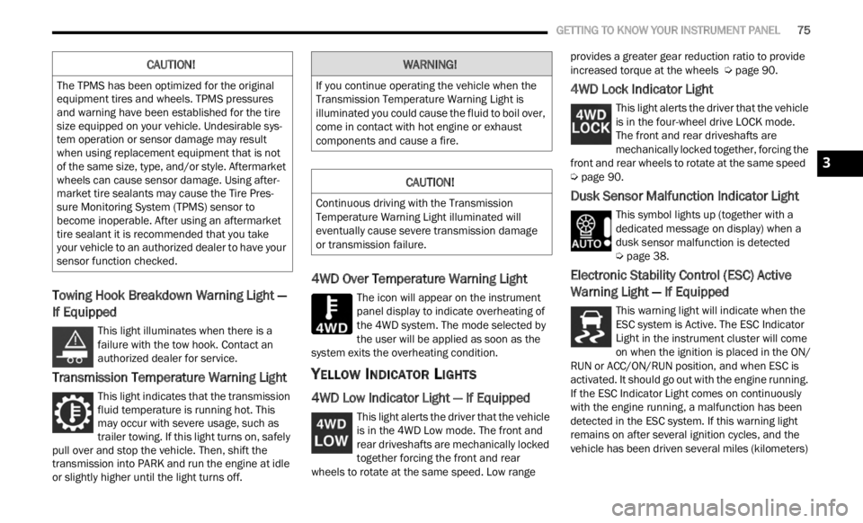
Towing Hook Breakdown Warning Light —
If Equipped
This light illuminates when there is a
failure with the tow hook. Contact an
a ut
h or
i
zed dealer for service.
Transmission Temperature Warning Light
This light indicates that the transmission
fluid temperature is running hot. This
may occ
ur with severe usage, such as
trailer towing. If this light turns on, safely
pull over and stop the vehicle. Then, shift the
transmission into PARK and run the engine at idle
or slightly higher until the light turns off.
4WD Over Temperature Warning Light
The icon will appear on the instrument
panel display to indicate overheating of
t h e
4
W
D system. The mode selected by
the user will be applied as soon as the
system exits the overheating condition.
YELLOW INDICATOR LIGHTS
4WD Low Indicator Light — If Equipped
This light alerts the driver that the vehicle
is in the 4WD Low mode. The front and
rear d
riveshafts are mechanically locked
together forcing the front and rear
wheels to rotate at the same speed. Low range provides a greater gear reduction ratio to provide
increased torque at the wheels
Ú page 90.
4WD Lock Indicator Light
This light alerts the driver that the vehicle
is in the four-wheel drive LOCK mode.
The f r
ont and rear driveshafts are
mechanically locked together, forcing the
front and rear wheels to rotate at the same speed
Ú page 90.
Dusk Sensor Malfunction Indicator Light
This symbol lights up (together with a
dedicated message on display) when a
dusk s
ensor malfunction is detected
Ú page 38.
Electronic Stability Control (ESC) Active
Warning Light — If Equipped
This warning light will indicate when the
ESC system is Active. The ESC Indicator
Light
in the instrument cluster will come
on when the ignition is placed in the ON/
RUN or ACC/ON/RUN position, and when ESC is
activated. It should go out with the engine running.
If the ESC Indicator Light comes on continuously
with the engine running, a malfunction has been
detected in the ESC system. If this warning light
remains on after several ignition cycles, and the
vehicle has been driven several miles (kilometers)
CAUTION!
The TPMS has been optimized for the original
equipment tires and wheels. TPMS pressures
and warning have been established for the tire
size equipped on your vehicle. Undesirable sys -
tem operation or sensor damage may result
w hen u
sing replacement equipment that is not
of the same size, type, and/or style. Aftermarket
wheels can cause sensor damage. Using after -
market tire sealants may cause the Tire Pres -
sure Monitoring System (TPMS) sensor to
b ecome
inoperable. After using an aftermarket
tire sealant it is recommended that you take
your vehicle to an authorized dealer to have your
sensor function checked.
WARNING!
If you continue operating the vehicle when the
Transmission Temperature Warning Light is
illuminated you could cause the fluid to boil over,
come in contact with hot engine or exhaust
components and cause a fire.
CAUTION!
Continuous driving with the Transmission
Temperature Warning Light illuminated will
eventually cause severe transmission damage
or transmission failure.
3
Page 78 of 364
76 GETTING TO KNOW YOUR INSTRUMENT PANEL
at speeds greater than 30 mph (48 km/h), see an
authori
zed dealer as soon as possible to have the
problem diagnosed and corrected.
The ESC OFF Indicator Light and the ESC Indi -
cator Light come on momentarily each time the
ignit i
on is placed in the ON/RUN or ACC/ON/
RUN position.
The ESC system will make buzzing or clicking
sounds when it is active. This is normal; the
sounds will stop when ESC becomes inactive.
This light will come on when the vehicle is in an
ESC event.
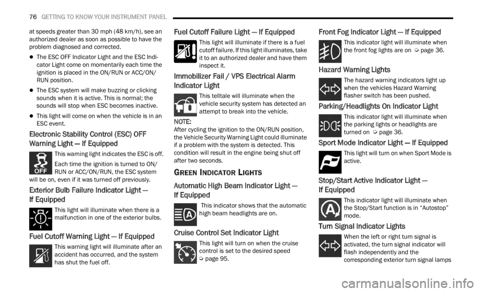
Electronic Stability Control (ESC) OFF
Warning Light — If Equipped
This warning light indicates the ESC is off.
Each time the ignition is turned to ON/
RUN or
ACC/ON/RUN, the ESC system
will be on, even if it was turned off previously.
Exterior Bulb Failure Indicator Light —
If Equipped
This light will illuminate when there is a
malfunction in one of the exterior bulbs.
Fuel Cutoff Warning Light — If Equipped
This warning light will illuminate after an
accident has occurred, and the system
has s h
ut the fuel off.
Fuel Cutoff Failure Light — If Equipped
This light will illuminate if there is a fuel
cutoff failure. If this light illuminates, take
it to a
n authorized dealer and have them
inspect it.
Immobilizer Fail / VPS Electrical Alarm
Indicator Light
This telltale will illuminate when the
vehicle security system has detected an
a tt
e m
p
t to break into the vehicle.
NOTE:
After cycling the ignition to the ON/RUN position,
the V e
hicle Security Warning Light could illuminate
if a problem with the system is detected. This
condition will result in the engine being shut off
after two seconds.
GREEN INDICATOR LIGHTS
Automatic High Beam Indicator Light —
If Equipped
This indicator shows that the automatic
high beam headlights are on.
Cruise Control Set Indicator Light
This light will turn on when the cruise
control is set to the desired speed
Ú page 95.
Front Fog Indicator Light — If Equipped
This indicator light will illuminate when
the front fog lights are on Ú page 36.
Hazard Warning Lights
The hazard warning indicators light up
when the vehicles Hazard Warning
flash e
r switch has been pushed.
Parking/Headlights On Indicator Light
This indicator light will illuminate when
the parking lights or headlights are
tu r
n e
d
on Ú page 36.
Sport Mode Indicator Light — If Equipped
This light will turn on when Sport Mode is
active.
Stop/Start Active Indicator Light —
If Equipped
This indicator light will illuminate when
the Stop/Start function is in “Autostop”
mode.
Turn Signal Indicator Lights
When the left or right turn signal is
activated, the turn signal indicator will
f la
sh
independently and the
corresponding exterior turn signal lamps
Page 84 of 364

82 STARTING AND OPERATING
NOTE:
If the vehicle fails to shut off using the ignition
Ú page 64.
Opening the driver side door with the ignition in
R UN w i
ll sound a short chime that reminds the
driver to place the ignition to OFF.
When the ignition is in the OFF position, the
window
switches remain active for three minutes.
Opening a front door will cancel this function.
After severe driving, idle the engine to allow the
tempe r
ature inside the engine compartment to
cool before shutting off the engine.
TURBOCHARGER “COOL DOWN” —
I
F EQUIPPED
This vehicle is equipped with an after-run pump to
cool the turbocharger after the engine is shut off.
Depending on the type of driving and the amount
of cargo, the pump will run for up to 10 minutes
after
the engine has been shut off to circulate
coolant through the turbocharger. Although the
pump is rubber-mounted for quiet operation, it is
normal to hear it running during this time.
ENGINE BREAK-IN RECOMMENDATIONS
A long break-in period is not required for the engine
and drivetrain (transmission and axle) in your
vehicle.
Drive moderately during the first 300 miles
(500 km
). After the initial 60 miles (100 km),
s p e
ed
s
up to 50 or 55 mph (80 or 90 km/h) are
desir a
ble.
While cruising, brief full-throttle acceleration within
the li
mits of local traffic laws contributes to a good
break-in. Wide-open throttle acceleration in low
gear can be detrimental and should be avoided.
The engine oil installed in the engine at the factory
is a h
igh-quality energy conserving type lubricant.
Oil changes should be consistent with anticipated
climate conditions under which vehicle operations
will occur. For the recommended viscosity and
quality grades Ú page 345.
NOTE:
A new engine may consume some oil during its first
few t h
ousand miles (kilometers) of operation. This
should be considered a normal part of the break-in
and not interpreted as a problem.
ELECTRIC PARK BRAKE (EPB)
Your vehicle is equipped with an EPB that offers
simple operation, and some additional features
that make the parking brake more convenient and
useful.
The parking brake is primarily intended to prevent
the ve
hicle from rolling while parked. Before
leaving the vehicle, make sure that the parking
brake is applied. Also, be certain to leave the
transmission in PARK.
The EPB switch is located in the center console.
You can engage the EPB in two ways:
Manually, by applying the parking brake switch.
Automatically, by enabling the Auto Park Brake
feature in the customer programmable features
section of the Uconnect settings or in “Safe
Hold” conditions.CAUTION!
Never use Non-Detergent Oil or Straight Mineral
Oil in the engine or damage may result.
Page 86 of 364
84 STARTING AND OPERATING
If exceptional circumstances should make it
necessary to engage the EPB while the vehicle is in
motion, maintain upward pressure on the EPB
switch for as long as engagement is desired. The
Brake Warning Light could illuminate in case the
hydraulic system is not available. The rear stop
lamps will also be illuminated automatically while
the vehicle remains in motion.
To disengage the EPB while the vehicle is in
motion,
release the switch. If the vehicle is brought
to a complete stop using the EPB, when the vehicle
reaches approximately 1.9 mph (3 km/h) the EPB
will r
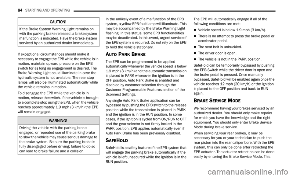
emain engaged. In the unlikely event of a malfunction of the EPB
syste
m
, a yellow EPB fault lamp will illuminate. This
may be accompanied by the Brake Warning Light
flashing. In this status, some EPB functionalities
may be deactivated. In this event, urgent service of
the EPB system is required. Do not rely on the EPB
to hold the vehicle stationary.
AUTO PARK BRAKE
The EPB can be programmed to be applied
automatically whenever the vehicle speed is below
1.9 mph (3 km/h) and the automatic transmission
is pla
ced in PARK whenever the ignition is in the
OFF position. Auto Park Brake is enabled and
disabled by customer selection through the
Customer Programmable Features section of the
Uconnect Settings.
Any single Auto Park Brake application can be
bypas s
ed by pushing the EPB switch to the release
position while the transmission is placed in PARK
and the ignition is in the RUN position. In some
cases, if the ignition is cycled from ON/RUN to OFF
and the gear selector is not firmly locked in the
PARK position, EPB applies automatically even if
Auto Park Brake has been previously disabled.
SAFEHOLD
SafeHold is a safety feature of the EPB system that
will engage the parking brake automatically if the
vehicle is left unsecured while the ignition is in the
RUN position. The EPB will automatically engage if all of the
followi
n
g conditions are met:
Vehicle speed is below 1.9 mph (3 km/h).
There is no attempt to press the brake pedal or
accelerator pedal.
The seat belt is unbuckled.
The driver door is open.
The vehicle is not in the PARK position.
SafeHold can be temporarily bypassed by pushing
the E P
B Switch while the driver door is open and
the brake pedal is pressed. Once manually
bypassed, SafeHold will be enabled again once the
vehicle reaches 12 mph (20 km/h) or the ignition
is pla
ced to the OFF position and back to RUN
again.
BRAKE SERVICE MODE
We recommend having your brakes serviced by an
authorized dealer. You should only make repairs
for which you have the knowledge and the right
equipment. You should only enter Brake Service
Mode during brake service.
When servicing your rear brakes, it may be
neces s
ary for you or your technician to push the
rear piston into the rear caliper bore. With the EPB
system, this can only be done after retracting the
EPB actuator. The actuator retraction can be done
easily by entering the Brake Service Mode. This
CAUTION!
If the Brake System Warning Light remains on
with the parking brake released, a brake system
malfunction is indicated. Have the brake system
serviced by an authorized dealer immediately.
WARNING!
Driving the vehicle with the parking brake
engaged, or repeated use of the parking brake
to slow the vehicle may cause serious damage to
the brake system. Be sure the parking brake is
fully disengaged before driving; failure to do so
can lead to brake failure and a collision.