reverse KIA CARNIVAL 2007 Workshop Manual
[x] Cancel search | Manufacturer: KIA, Model Year: 2007, Model line: CARNIVAL, Model: KIA CARNIVAL 2007Pages: 1575, PDF Size: 44.86 MB
Page 1307 of 1575
2007 > 2.7L V6 GASOLINE >
REPLACEMENT
1.Disconnect the negative ( - ) battery terminal.
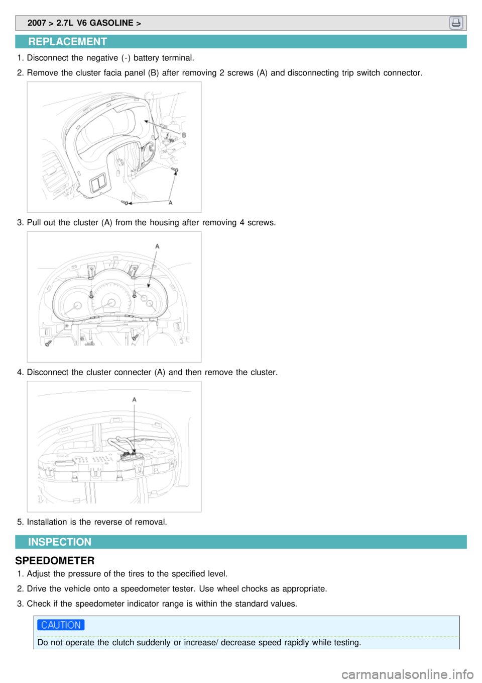
2. Remove the cluster facia panel (B) after removing 2 screws (A) and disconnecting trip switch connector.
3.Pull out the cluster (A) from the housing after removing 4 screws.
4.Disconnect the cluster connecter (A) and then remove the cluster.
5.Installation is the reverse of removal.
INSPECTION
SPEEDOMETER
1. Adjust the pressure of the tires to the specified level.
2. Drive the vehicle onto a speedometer tester. Use wheel chocks as appropriate.
3. Check if the speedometer indicator range is within the standard values.
Do not operate the clutch suddenly or increase/ decrease speed rapidly while testing.
Page 1323 of 1575

2007 > 2.7L V6 GASOLINE >
DESCRIPTION
Power Sliding Door is an electro - mechanical system designed to provide power opening and closing of a vehicle's
sliding door through the push of a button of the transmitter key or the main control buttons on the overhead console
or the sub control buttons on the center pillar trim or inside/outside door handle switch.
The power sliding door will reverse direction of travel if resistance to movement is detected while the door is being
closed. If resistance to movement is detected while the power sliding door is being opened, the door will stop moving.
1. DRIVE UNIT
Drive unit (A) consists of a DC motor, optical sensor, clutch, cables and pulleys and wire harness. The clutch and
motor portion of the assembly provides the power and torque required to open or close the sliding door. The clutch
assembly is used to connect or disconnect the motor so that the Sliding Door may be moved manually, if desired.
2.POWER SLIDING DOOR CONTROL MODULE (PSDM)
The PSD System uses a power sliding door control module (microprocessor controller) to operate the drive unit.
Signals are received from the vehicle and used to start or stop power open or close operations. The PSDM cannot
be adjusted or repaired and if found to be faulty, must be replaced.
3.SLIDING DOOR CHIME (C)
When the power sliding door detect the resistance or abnormal operation, the chime will sound.
4.ANTI- PINCH STRIP (D)
Page 1342 of 1575

TORQUE : 7 - 11 N.m (0.7 - 1.1 Kg.m)
10.Loosen the mounting bolt (1EA) and nuts (2EA). And then remove the power sliding door drive unit assembly after
removing the front cable.
TORQUE : 7 - 11 N.m (0.7 - 1.1 Kg.m)
11. Installation is the reverse of removal.
12. When installation, check the grease on the center roller hinge barrel and club contact part (A).
a.A learn cycle must be performed whenever the power is removed.
b. Check the normal operation whenever a power sliding door component is removed or replaced. If the
chime sound is heard, check the DTC, wiring harness and cable connections.
Page 1344 of 1575

2007 > 2.7L V6 GASOLINE >
REPLACEMENT
1.Disconnect the negative ( - ) battery terminal..
2. Remove the rear trim panel (Refer to the Body group - interior trim)
3. Remove the connectors and mounting bolts (2EA) from the power sliding door unit(A). And then remove the power
sliding door control module (B).
TORQUE 0.25 - 0.35N.m(0.025- 0.035Kg.m)
4.Installation is the reverse of removal.
a.A learn cycle must be performed whenever the power is removed.
b. Check the normal operation whenever a power sliding door component is removed or replaced. If the
chime sound is heard, check the DTC, wiring harness and cable connections.
Page 1357 of 1575

3.Installation is the reverse of removal.
DOOR TRIM SWITCH
1.Disconnect the negative ( - ) battery terminal.
2. Remove the connector (B) and door trim switch (A) from the center pillar (C) by using the scraper.
3.Installation is the reverse of removal.
Page 1364 of 1575

2007 > 2.7L V6 GASOLINE >
REPLACEMENT
1.Disconnect the negative ( - ) battery terminal.
2. Remove the front door trim panel. (Refer to the Body group - front door)
3. Remove the power window main switch mounting screws (3EA) (A) after disconnecting the switch connector
(12pin) from the switch.
4.Remove the switch from the front door trim panel.
5. Installation is the reverse of removal.
INSPECTION
1.Disconnect the 12P connector from the switch.
2.Check for continuity between the terminals in each switch position according to the table.
Page 1367 of 1575

2007 > 2.7L V6 GASOLINE >
DESCRIPTION
Power tail gate is an electro - mechanical system designed to provide power opening and closing of a vehicle’s tail gate
through the push of a button of the transmitter key or tail gate handle or the overhead console or switch of the tail
gate.
The power tail gate will reverse direction of travel if resistance to movement is detected while the tail gate is being
closed. If resistance to movement is detected while the power tail gate is being opened, the tail gate will stop moving.
1. PTG DRIVE UNIT
Power tailgate drive unit consists of a DC motor, optical sensor, clutch, push rod, rack and wire harness.
PTG drive unit is located in rear left on D- pillar panel. PTG drive unit opens and closes the tail gate connected
push rod automatically.
a.Optical sensor : Provides tail gate velocity and position information
b. Drive unit clutch : Transmit motor power to push rod through pinion gear.
2. POWER LATCH
Power latch is located in the lower part of tail gate panel. When tail gate located latching position, cinching motor
(A) has a cinch electrically. And unlatch motor (B) unlatch the latch electrically when receive the open signal.
3.ANTI PINCH STRIP (C)
During power closing or cinching, the PTG system shall reverse to full open if an anti- pinch strip signal is received.
However, the anti- pinch strips will not work when the Tailgate is idle in the full closed, full open, or stopped
positions.
Page 1368 of 1575

4.PTG CHIME (D)
When a power operation cannot be performed as requested or an obstacle has been detected.
5.REMOTE KEYLESS ENTRY (A)
Push the power tail gate (A) of the remote keyless entry more than 0.5s to open the power tail gate. Power Open
operation shall be reversed when an additional Open/Close signal is received during power opening.
6. OPERATING ORDER
Switch ON → clutch on → motor operation → pinion gear rotation → rack rectilinear motion → push rod motion →
tail gate open/close
OPERATION
POWER TAIL GATE OPEN/CLOSE
1. The power tail gate is opened and closed automatically if the main switch (A) is pressed on the overhead console.
Page 1369 of 1575
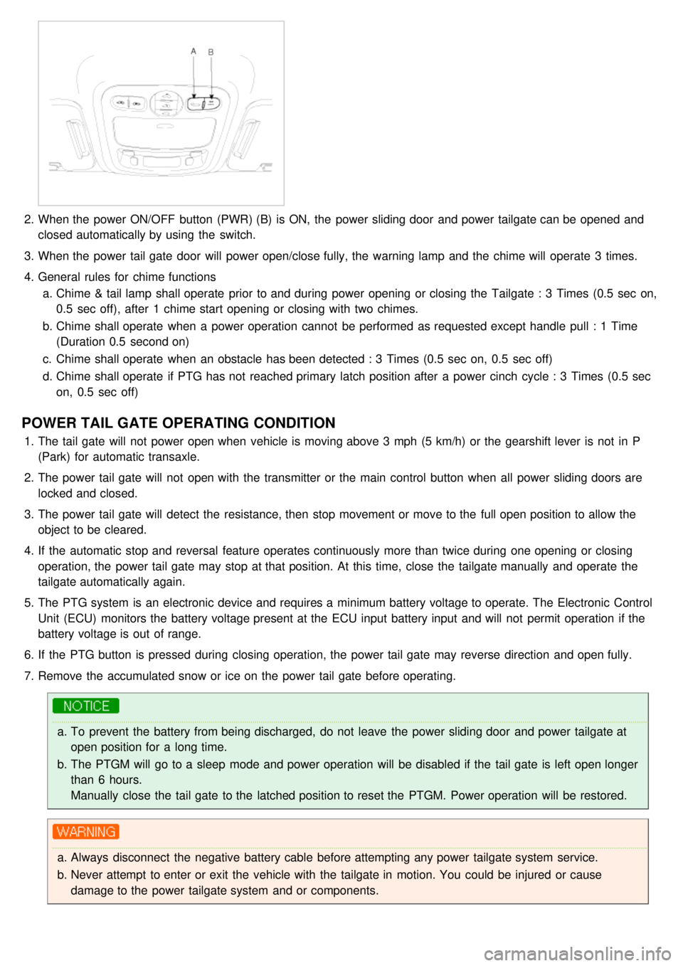
2.When the power ON/OFF button (PWR) (B) is ON, the power sliding door and power tailgate can be opened and
closed automatically by using the switch.
3. When the power tail gate door will power open/close fully, the warning lamp and the chime will operate 3 times.
4. General rules for chime functions
a. Chime & tail lamp shall operate prior to and during power opening or closing the Tailgate : 3 Times (0.5 sec on,
0.5 sec off), after 1 chime start opening or closing with two chimes.
b. Chime shall operate when a power operation cannot be performed as requested except handle pull : 1 Time
(Duration 0.5 second on)
c. Chime shall operate when an obstacle has been detected : 3 Times (0.5 sec on, 0.5 sec off)
d. Chime shall operate if PTG has not reached primary latch position after a power cinch cycle : 3 Times (0.5 sec
on, 0.5 sec off)
POWER TAIL GATE OPERATING CONDITION
1.The tail gate will not power open when vehicle is moving above 3 mph (5 km/h) or the gearshift lever is not in P
(Park) for automatic transaxle.
2. The power tail gate will not open with the transmitter or the main control button when all power sliding doors are
locked and closed.
3. The power tail gate will detect the resistance, then stop movement or move to the full open position to allow the
object to be cleared.
4. If the automatic stop and reversal feature operates continuously more than twice during one opening or closing
operation, the power tail gate may stop at that position. At this time, close the tailgate manually and operate the
tailgate automatically again.
5. The PTG system is an electronic device and requires a minimum battery voltage to operate. The Electronic Control
Unit (ECU) monitors the battery voltage present at the ECU input battery input and will not permit operation if the
battery voltage is out of range.
6. If the PTG button is pressed during closing operation, the power tail gate may reverse direction and open fully.
7. Remove the accumulated snow or ice on the power tail gate before operating.
a.To prevent the battery from being discharged, do not leave the power sliding door and power tailgate at
open position for a long time.
b. The PTGM will go to a sleep mode and power operation will be disabled if the tail gate is left open longer
than 6 hours.
Manually close the tail gate to the latched position to reset the PTGM. Power operation will be restored.
a.Always disconnect the negative battery cable before attempting any power tailgate system service.
b. Never attempt to enter or exit the vehicle with the tailgate in motion. You could be injured or cause
damage to the power tailgate system and or components.
Page 1381 of 1575
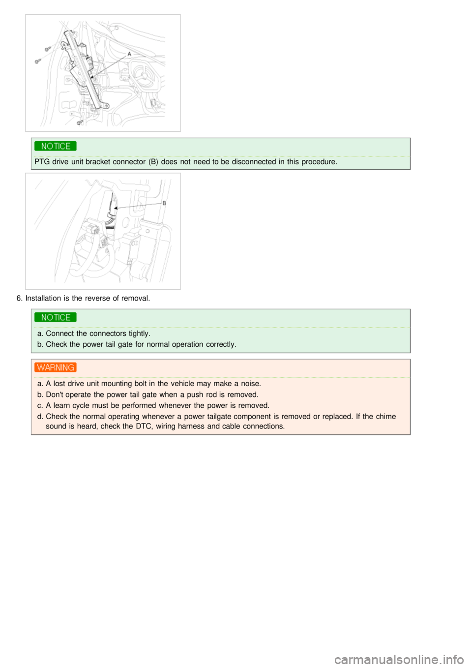
PTG drive unit bracket connector (B) does not need to be disconnected in this procedure.
6.Installation is the reverse of removal.
a.Connect the connectors tightly.
b. Check the power tail gate for normal operation correctly.
a.A lost drive unit mounting bolt in the vehicle may make a noise.
b. Don't operate the power tail gate when a push rod is removed.
c. A learn cycle must be performed whenever the power is removed.
d. Check the normal operating whenever a power tailgate component is removed or replaced. If the chime
sound is heard, check the DTC, wiring harness and cable connections.