KIA CARNIVAL 2007 Workshop Manual
CARNIVAL 2007
KIA
KIA
https://www.carmanualsonline.info/img/2/57045/w960_57045-0.png
KIA CARNIVAL 2007 Workshop Manual
Page 1263 of 1575
2007 > 2.7L V6 GASOLINE >
REPLACEMENT
1.Disconnect the negative ( - ) battery terminal.
2. Remove the seat back (Refer to Body group - front seat).
3.Remove the power seat module after removing the power seat module mounting nuts (4EA) and connector (3EA).
4.Installation is the reverse of removal.
Page 1265 of 1575
2007 > 2.7L V6 GASOLINE >
REPLACEMENT
1.Remove the negative ( - ) battery terminal.
2. Remove the front door trim panel in the car. (Refer to the Body group - front door)
3. Remove the switch (A) mounting screws (3EA) after disconnecting the 16pin switch connector.
4.Remove the connector from the front door trim panel.
5. Installation is the reverse of removal.
Page 1268 of 1575
2007 > 2.7L V6 GASOLINE >
REPLACEMENT
FRONT HEIGHT MOTOR
1. Disconnect the negative ( - ) battery terminal.
2. Remove the seat cushion (Refer to Body group - front seat).
3. Remove the front height motor (A) after loosening the mounting nuts (2EA) , bolt (1EA) and removing connector.
4.Installation is the reverse of removal.
REAR HEIGHT MOTOR
1.Disconnect the negative ( - ) battery terminal.
2. Remove the seat cushion (Refer to Body group - front seat).
3. Remove the rear height motor (A) after removing the mounting bolt (2EA) and connector.
4.Installation is the reverse of removal.
SLIDE MOTOR
1.Disconnect the negative ( - ) battery terminal.
2. Remove the seat cushion (Refer to Body group - front seat).
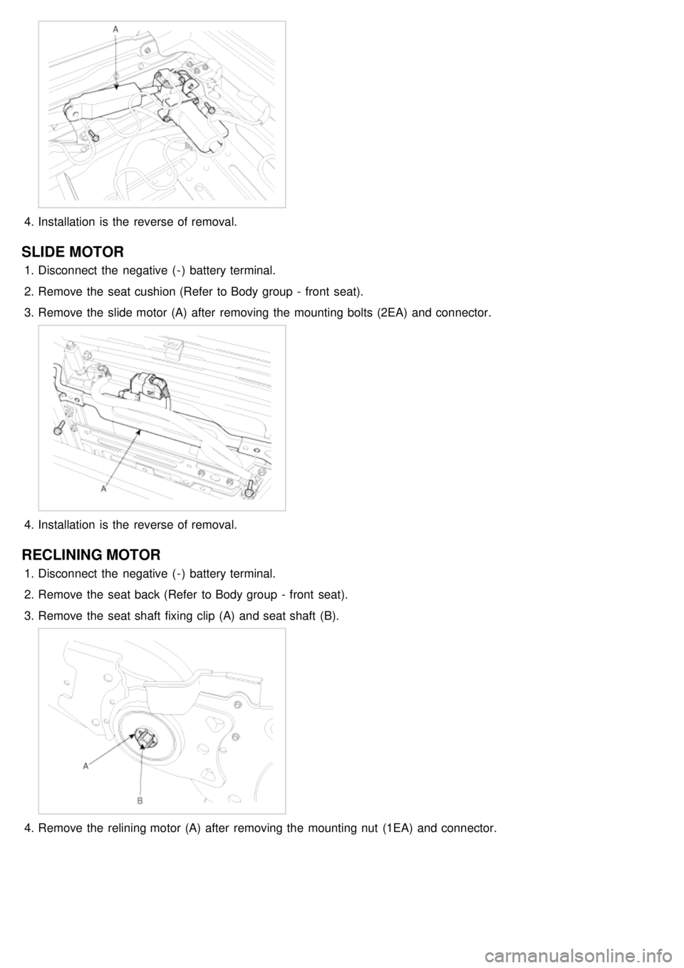
3. Remove the slide motor (A) after removing the mounting bolt (2EA) and connector.
Page 1269 of 1575
4.Installation is the reverse of removal.
SLIDE MOTOR
1.Disconnect the negative ( - ) battery terminal.
2. Remove the seat cushion (Refer to Body group - front seat).
3. Remove the slide motor (A) after removing the mounting bolts (2EA) and connector.
4.Installation is the reverse of removal.
RECLINING MOTOR
1.Disconnect the negative ( - ) battery terminal.
2. Remove the seat back (Refer to Body group - front seat).
3. Remove the seat shaft fixing clip (A) and seat shaft (B).
4.Remove the relining motor (A) after removing the mounting nut (1EA) and connector.
Page 1270 of 1575
5.Installation is the reverse of removal.
INSPECTION
SLIDE MOTOR LIMIT SWITCH
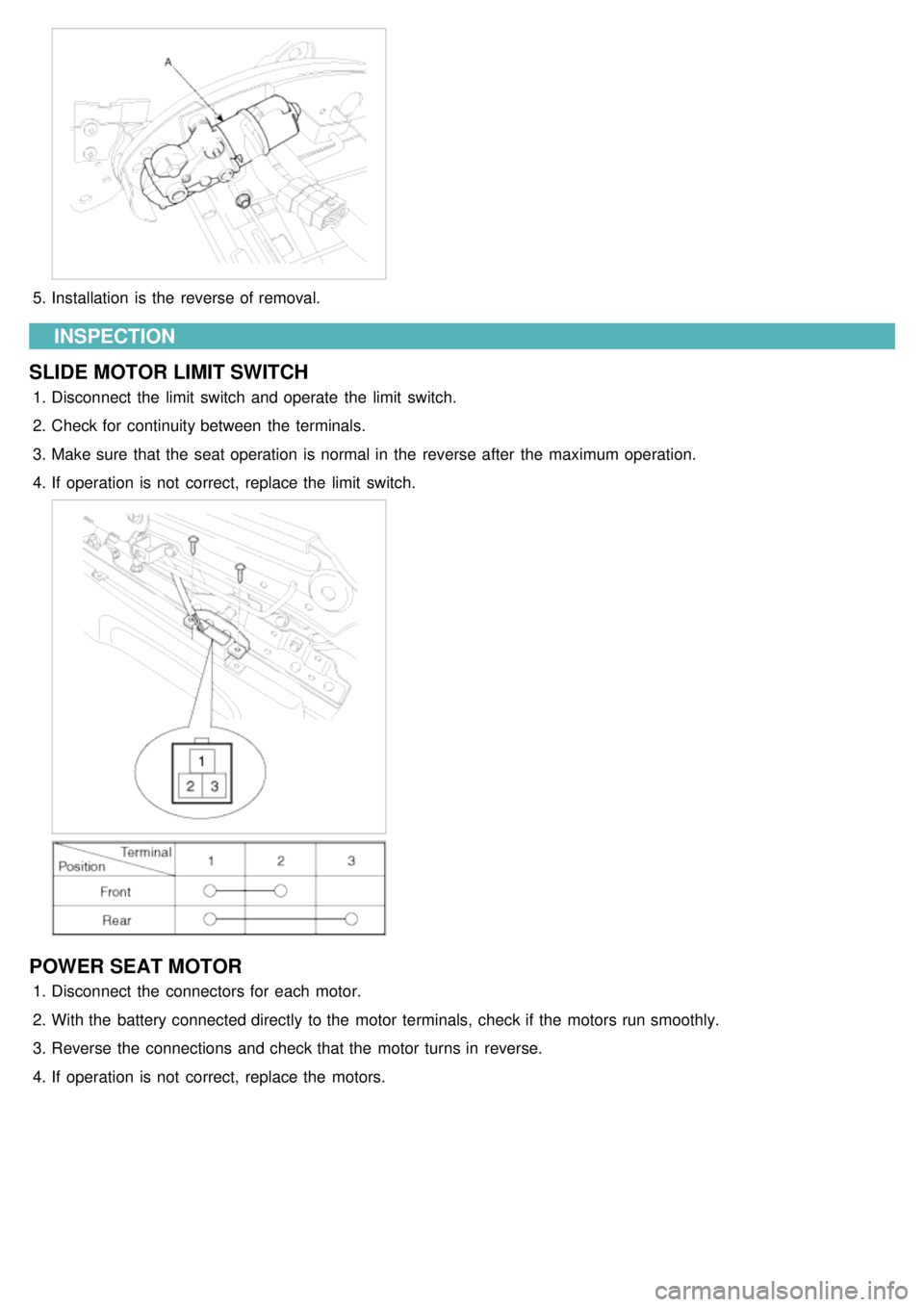
1. Disconnect the limit switch and operate the limit switch.
2. Check for continuity between the terminals.
3. Make sure that the seat operation is normal in the reverse after the maximum operation.
4. If operation is not correct, replace the limit switch.
POWER SEAT MOTOR
1.Disconnect the connectors for each motor.
2. With the battery connected directly to the motor terminals, check if the motors run smoothly.
3. Reverse the connections and check that the motor turns in reverse.
4. If operation is not correct, replace the motors.
Page 1272 of 1575
2007 > 2.7L V6 GASOLINE >
REPLACEMENT
1.Disconnect the nagative(- ) battery terminal.
2. Remove the door trim panel (Refer to Body group - front door).
3. Remove the switch connector (16pin) from the wiring harness, And then loosen the mounting screws (3EA).
4.Remove the switch from the front door panel.
5. Installation is the reverse of removal.
Page 1274 of 1575
2007 > 2.7L V6 GASOLINE >
INSPECTION
1.Disconnect the negative ( - ) battery terminal.
2. Remove the seat back (Refer to Body group - front seat).
3.Remove the mounting screw, center facia panel switch and then disconnect connectors.
4.Remove the seat warmer switch (A) from center facia panel switch.
5.Installation is the reverse of removal.
Page 1276 of 1575
2007 > 2.7L V6 GASOLINE >
REPLACEMENT
1.Disconnect the negative ( - ) battery terminal.
2. Remove the seat cushion (A) (Refer to Body group - front seat)
3.Remove the seat heater module (B) after removing seat heater module mounting screw (2EA) and connector from
rear height motor (A).
4.Installation is the reverse of removal.
Page 1292 of 1575
3.If system of some relay is not operate accurately, replace with a new one and check the system.
REPLACEMENT
FAM (FRONT AREA MODULE)
1. Disconnect the negative ( - ) battery terminal.
2. Remove the FAM cover of engine room.
3. Remove the FAM connectors (2EA) (A) and battery terminal nut (1EA) (B).
4.Remove FAM mounting bolts (3EA) (A) and remove the FAM (B) from splash shield (C).
5.Disconnect the connector from splash shield.
6. Installation is the reverse of removal.
Page 1299 of 1575
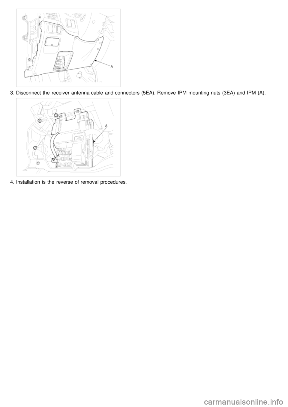
3.Disconnect the receiver antenna cable and connectors (5EA). Remove IPM mounting nuts (3EA) and IPM (A).
4.Installation is the reverse of removal procedures.