reverse KIA CARNIVAL 2007 Workshop Manual
[x] Cancel search | Manufacturer: KIA, Model Year: 2007, Model line: CARNIVAL, Model: KIA CARNIVAL 2007Pages: 1575, PDF Size: 44.86 MB
Page 1182 of 1575
2007 > 2.7L V6 GASOLINE >
REPLACEMENT
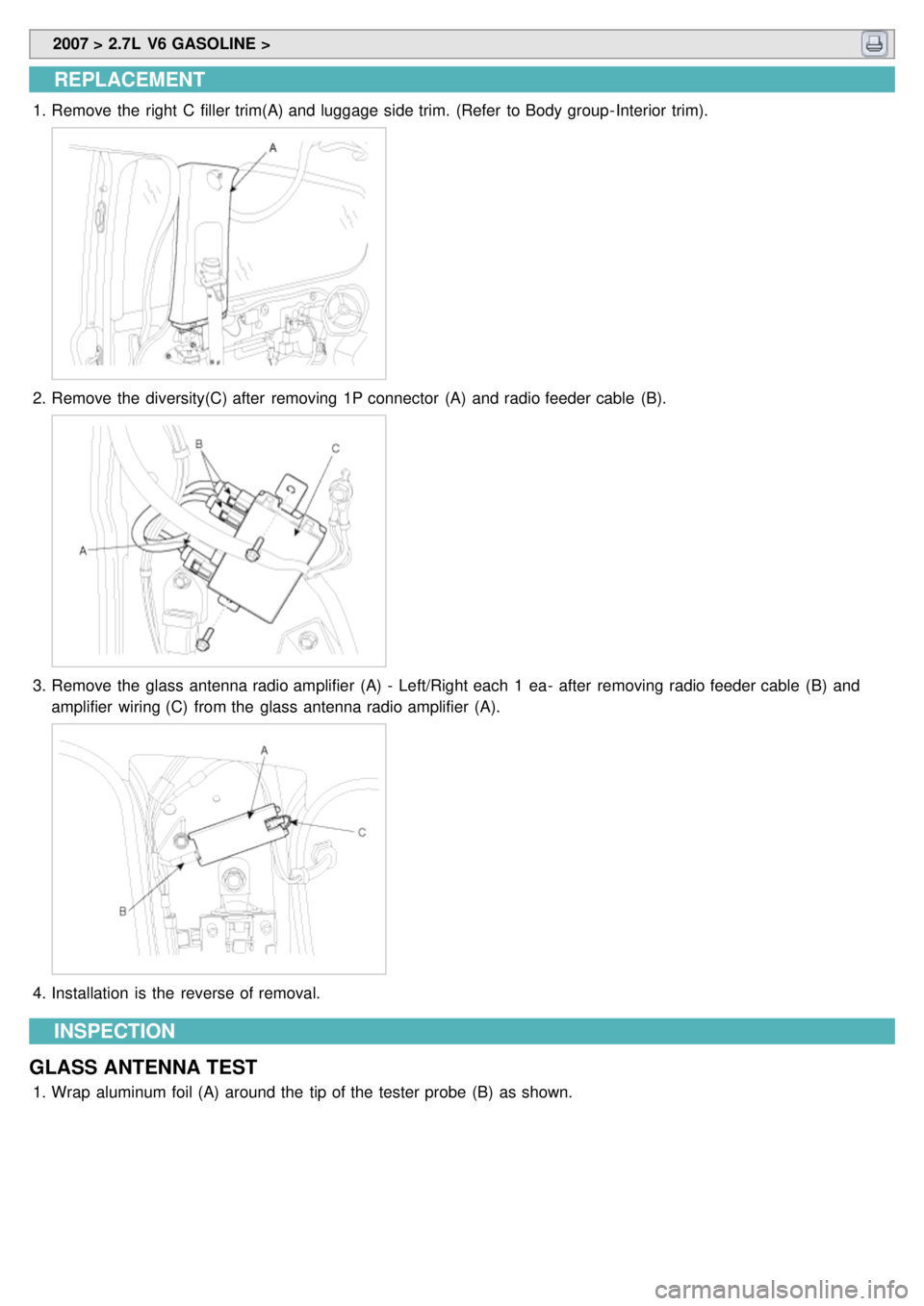
1.Remove the right C filler trim(A) and luggage side trim. (Refer to Body group - Interior trim).
2.Remove the diversity(C) after removing 1P connector (A) and radio feeder cable (B).
3.Remove the glass antenna radio amplifier (A) - Left/Right each 1 ea- after removing radio feeder cable (B) and
amplifier wiring (C) from the glass antenna radio amplifier (A).
4.Installation is the reverse of removal.
INSPECTION
GLASS ANTENNA TEST
1. Wrap aluminum foil (A) around the tip of the tester probe (B) as shown.
Page 1189 of 1575

2007 > 2.7L V6 GASOLINE >
REPLACEMENT
1.Disconnect the negative ( - ) battery terminal.
2. Remove the driver airbag module(A). (Refer to the airbag group).
3.Remove the audio remote control switch (A) after removing the steering wheel remote control switch connector and
2 screws.
4.Installation is the reverse of removal.
INSPECTION
1.Check for resistance between No.2 and No.3 terminals in each switch position.
Switch Connector terminal Resistance (±5%)
MODE 2 - 3 (Left) 2.11 kΩ
MUTE 2 - 3 (Left) 3.11 kΩ
VOLUME UP 2 - 3 (Left) 4.61 kΩ
VOLUME DOWN 2 - 3 (Left)5.81 kΩ
Page 1195 of 1575

4.Remove the wiper switch (A) after disconnecting the connector and pin(B).
[LHD]
[RHD]
5.Installation is the reverse of removal.
Page 1198 of 1575

2007 > 2.7L V6 GASOLINE >
REPLACEMENT
1.Remove the bolt from the high pitch horn and the low pitch horn and disconnect the horn connector, then remove
the horn.
2.Installation is the reverse of removal.
INSPECTION
Test the horn by connecting battery voltage to the terminal 1, and ground terminal 2.
The horn should make a sound. If the horn fails to make a sound, replace it.
ADJUSTMENT
Operate the horn, and adjust the tone to a suitable level by turning the adjusting screw.
After adjustment, apply a small amount of paint around the screw head to keep it from loosening.
Page 1225 of 1575
Adjustable Pedal(non-ims)
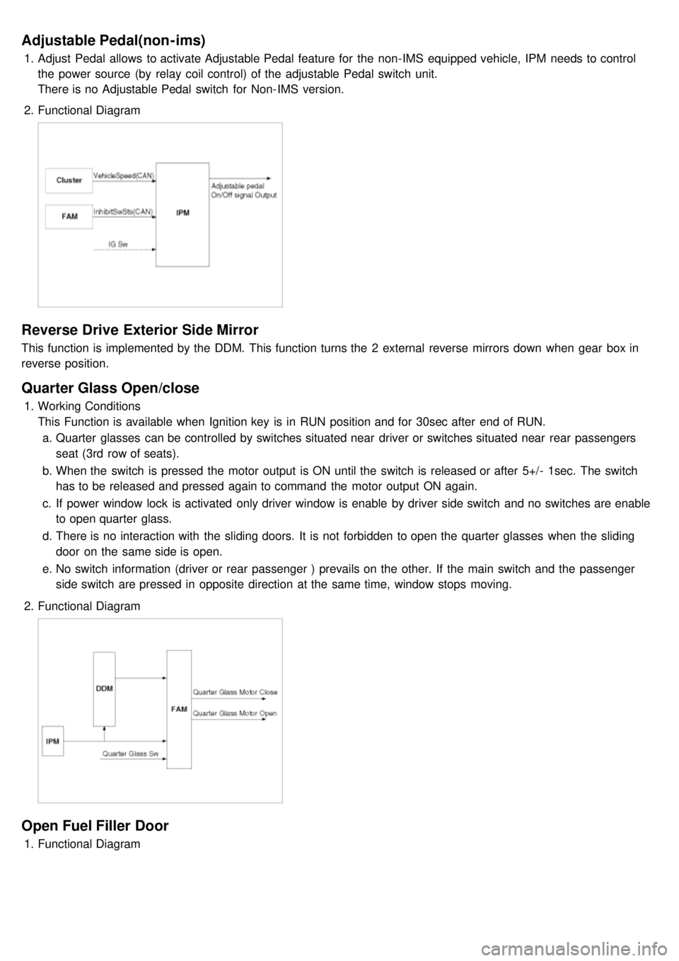
1.Adjust Pedal allows to activate Adjustable Pedal feature for the non- IMS equipped vehicle, IPM needs to control
the power source (by relay coil control) of the adjustable Pedal switch unit.
There is no Adjustable Pedal switch for Non- IMS version.
2. Functional Diagram
Reverse Drive Exterior Side Mirror
This function is implemented by the DDM. This function turns the 2 external reverse mirrors down when gear box in
reverse position.
Quarter Glass Open/close
1.Working Conditions
This Function is available when Ignition key is in RUN position and for 30sec after end of RUN.
a. Quarter glasses can be controlled by switches situated near driver or switches situated near rear passengers
seat (3rd row of seats).
b. When the switch is pressed the motor output is ON until the switch is released or after 5+/- 1sec. The switch
has to be released and pressed again to command the motor output ON again.
c. If power window lock is activated only driver window is enable by driver side switch and no switches are enable
to open quarter glass.
d. There is no interaction with the sliding doors. It is not forbidden to open the quarter glasses when the sliding
door on the same side is open.
e. No switch information (driver or rear passenger ) prevails on the other. If the main switch and the passenger
side switch are pressed in opposite direction at the same time, window stops moving.
2. Functional Diagram
Open Fuel Filler Door
1.Functional Diagram
Page 1242 of 1575
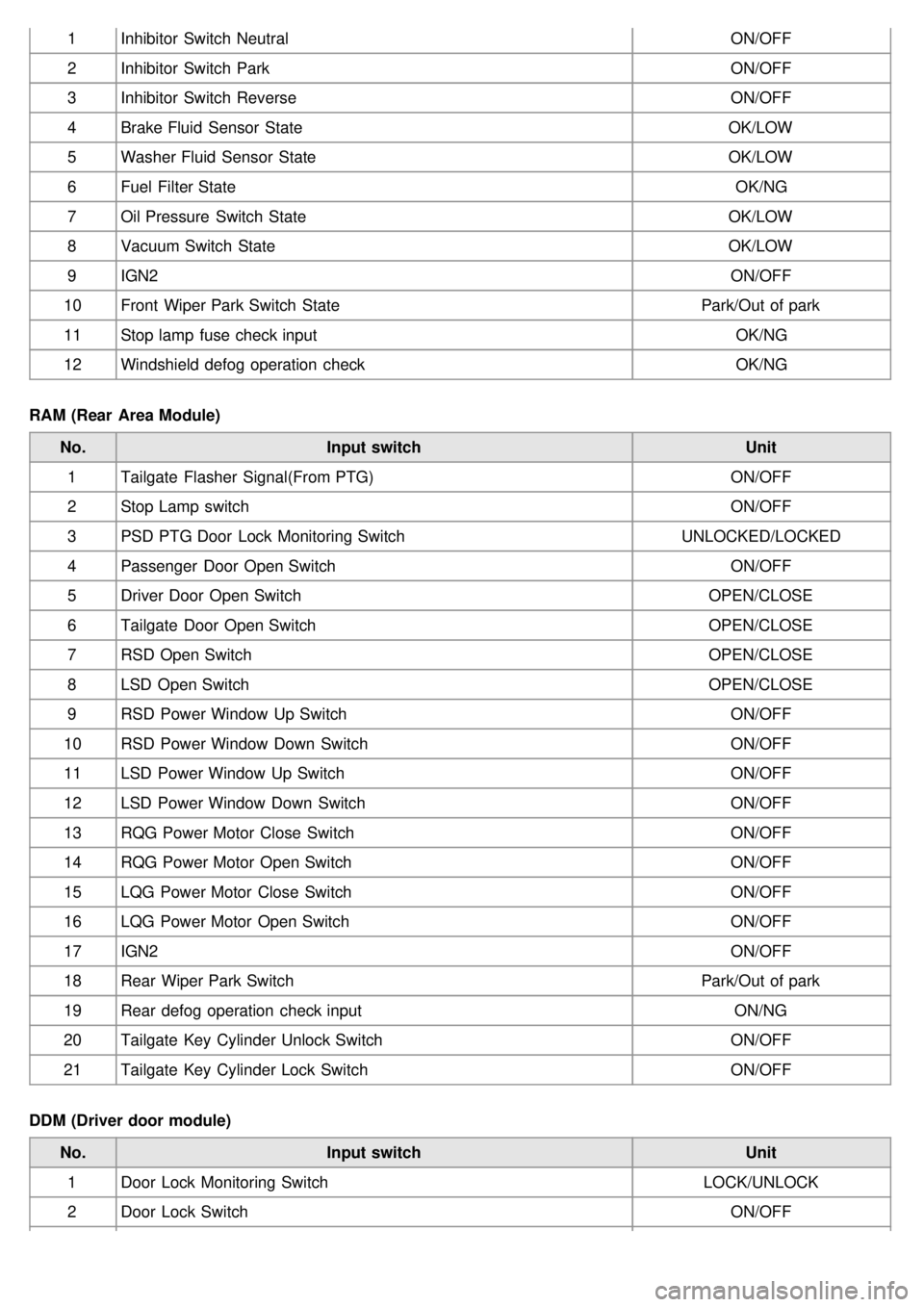
1Inhibitor Switch Neutral ON/OFF
2 Inhibitor Switch Park ON/OFF
3 Inhibitor Switch Reverse ON/OFF
4 Brake Fluid Sensor State OK/LOW
5 Washer Fluid Sensor State OK/LOW
6 Fuel Filter State OK/NG
7 Oil Pressure Switch State OK/LOW
8 Vacuum Switch State OK/LOW
9 IGN2 ON/OFF
10 Front Wiper Park Switch State Park/Out of park
11 Stop lamp fuse check input OK/NG
12 Windshield defog operation check OK/NG
RAM (Rear Area Module) No. Input switch Unit
1 Tailgate Flasher Signal(From PTG) ON/OFF
2 Stop Lamp switch ON/OFF
3 PSD PTG Door Lock Monitoring Switch UNLOCKED/LOCKED
4 Passenger Door Open Switch ON/OFF
5 Driver Door Open Switch OPEN/CLOSE
6 Tailgate Door Open Switch OPEN/CLOSE
7 RSD Open Switch OPEN/CLOSE
8 LSD Open Switch OPEN/CLOSE
9 RSD Power Window Up Switch ON/OFF
10 RSD Power Window Down Switch ON/OFF
11 LSD Power Window Up Switch ON/OFF
12 LSD Power Window Down Switch ON/OFF
13 RQG Power Motor Close Switch ON/OFF
14 RQG Power Motor Open Switch ON/OFF
15 LQG Power Motor Close Switch ON/OFF
16 LQG Power Motor Open Switch ON/OFF
17 IGN2 ON/OFF
18 Rear Wiper Park Switch Park/Out of park
19 Rear defog operation check input ON/NG
20 Tailgate Key Cylinder Unlock Switch ON/OFF
21 Tailgate Key Cylinder Lock Switch ON/OFF
DDM (Driver door module) No. Input switch Unit
1 Door Lock Monitoring Switch LOCK/UNLOCK
2 Door Lock Switch ON/OFF
Page 1252 of 1575

4.Installation is the reverse of removal.
FAM (Front Area Module)
1.Disconnect the negative ( - ) battery terminal.
2. Remove the FAM cover from the engine room.
3. Remove the 2 FAM connectors(A) and battery terminal nut(B).
4.Remove the IPM(B) from the splesh shield(C) after loosening the 3 IPM mounting bolts(A) and the IPM mounting
clip.
5.Disconnect the connector from the splesh shield.
6. Installation is the reverse of removal.
RAM (Rear Area Module)
1.Disconnect the negative ( - ) battery terminal.
2. Remove the left luggage side trim
(Refer to the Body group - interior trim)
3. Remove the RAM(A) after loosening the 7 connectors and the 3 RAM mounting bolts(A).
Page 1253 of 1575

4.Installation is the reverse of removal.
Page 1256 of 1575

2007 > 2.7L V6 GASOLINE >
REPLACEMENT
1.Remove the negative ( - ) battery terminal.
2. Remove the seats in the car. (Refer to the Body group - front seats)
3.Remove the IMS module (A) after loosening 4 nuts and 3 connectors in the bottom of seat.
4.Installation is the reverse of removal.
Page 1260 of 1575
4.Operation control
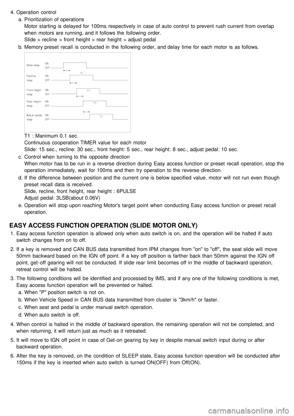
a. Prioritization of operations
Motor starting is delayed for 100ms respectively in case of auto control to prevent rush current from overlap
when motors are running, and it follows the following order.
Slide > recline > front height > rear height > adjust pedal
b. Memory preset recall is conducted in the following order, and delay time for each motor is as follows.
T1 : Manimum 0.1 sec.
Continuous cooperation TIMER value for each motor
Slide: 15 sec., recline: 30 sec., front height: 5 sec., rear height: 8 sec., adjust pedal: 10 sec.
c. Control when turning to the opposite direction
When motor has to be run in a reverse direction during Easy access function or preset recall operation, stop the
operation immediately, wait for 100ms and then try operation to the reverse direction.
d. If the difference between position and the current one is below specified value, motor will not run even though
preset recall data is received.
Slide, recline, front height, rear height : 6PULSE
Adjust pedal: 3LSB(about 0.06V)
e. Operation will stop upon reaching Motor's target point when conducting Easy access function or preset recall
operation.
EASY ACCESS FUNCTION OPERATION (SLIDE MOTOR ONLY)
1.Easy access function operation is allowed only when auto switch is on, and the operation will be halted if auto
switch changes from on to off.
2. If a key is removed and CAN BUS data transmitted from IPM changes from "on" to "off", the seat slide will move
50mm backward based on the IGN off point. If a key off position is farther back than 50mm against the IGN off
point, get - off gearing will not be conducted. If slide rear limit becomes off in the middle of backward operation,
retreat control will be halted.
3. The following conditions will be identified and processed by IMS, and if any one of the following conditions is met,
Easy access function operation will be prevented or halted.
a. When "P" position switch is not on.
b. When Vehicle Speed in CAN BUS data transmitted from cluster is "3km/h" or faster.
c. When seat and pedal is under manual switch operation.
d. When auto switch is off.
4. When control is halted in the middle of backward operation, the remaining operation will not be completed, and
when returning, it will return just as much as it retreated.
5. It will move to IGN off point in case of Get- on gearing by key in despite manual switch input during or after
backward operation.
6. After the key is removed, on the condition of SLEEP state, Easy access function operation will be conducted after
150ms if the key is inserted when auto switch is turned ON(OFF) from Off(ON).