KIA CARNIVAL 2007 Workshop Manual
CARNIVAL 2007
KIA
KIA
https://www.carmanualsonline.info/img/2/57045/w960_57045-0.png
KIA CARNIVAL 2007 Workshop Manual
Page 1457 of 1575
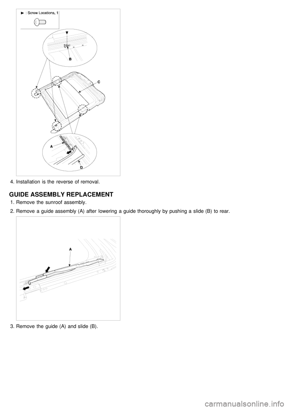
4.Installation is the reverse of removal.
GUIDE ASSEMBLY REPLACEMENT
1.Remove the sunroof assembly.
2. Remove a guide assembly (A) after lowering a guide thoroughly by pushing a slide (B) to rear.
3.Remove the guide (A) and slide (B).
Page 1458 of 1575
4.Installation is the reverse of removal.
a.Make sure to align the slide with the center of “A” and “B”
b. Make sure to initialize the motor.
ADJUSTMENT
HOW TO INITIALIZE
1. Check that the glass has been installed.
a. Finish height adjustment.
2. Push the up switch. (Keep on pushing the switch)
a. The slide moved 5mm forward after 15 seconds.
Page 1469 of 1575
2007 > 2.7L V6 GASOLINE >
REPLACEMENT
1.Disconnect the negative ( - ) battery terminal.
2. Loose the mounting bolts (2EA).
3.Remove the head lamp assembly after disconnecting the lamp connectors.
Take care that holding clip (A) is not to be damaged.
4.Remove the head lamp rear cover and pulling up head lamp bulb fixing wire clip.
5.Replace the bulb.
6. Installation is the reverse of removal.
HEAD LAMP AIMING INSTRUCTIONS
Alternately turn the adjusting gear to adjust the head lamp aiming. If beam- setting equipment is not available, proceed
as follows :
1. Inflate the tires to the specified pressure and remove any loads from the vehicle except the driver, spare tire, and
tools.
Page 1477 of 1575
2007 > 2.7L V6 GASOLINE >
REPLACEMENT
1.Disconnect the negative ( - ) battery terminal.
2. Detach the lamp lens from the room lamp with a flat- tip screwdriver ( - ) then replace the bulb.
3.Pull the bulb down and replace it with a new one.
Take care that holding clip (A) is not to be damaged.
4. Installation is the reverse of removal.
Page 1489 of 1575
2007 > 2.7L V6 GASOLINE >
REPLACEMENT
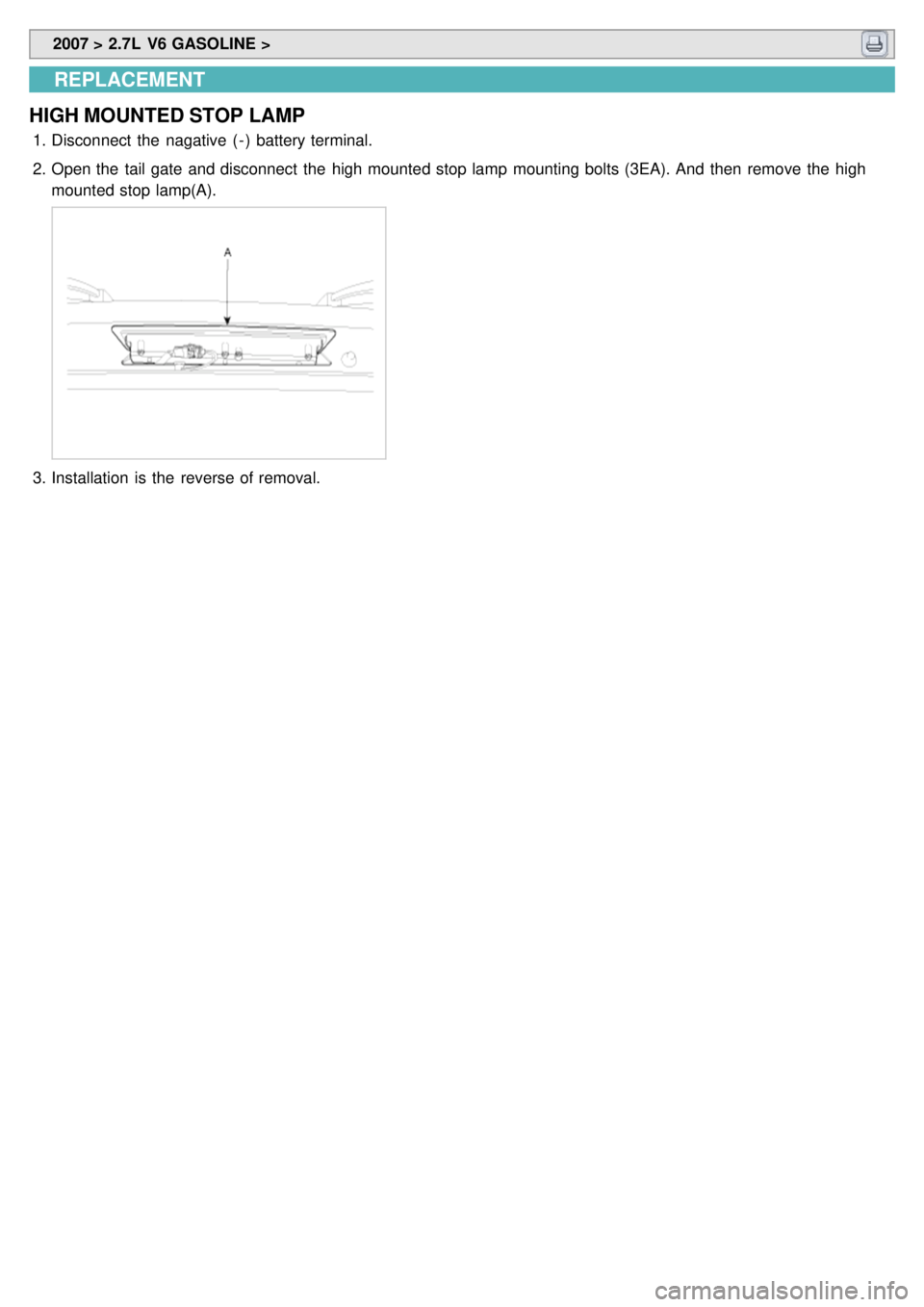
HIGH MOUNTED STOP LAMP
1. Disconnect the nagative ( - ) battery terminal.
2. Open the tail gate and disconnect the high mounted stop lamp mounting bolts (3EA). And then remove the high
mounted stop lamp(A).
3.Installation is the reverse of removal.
Page 1496 of 1575

2007 > 2.7L V6 GASOLINE >
INSPECTION
While operating the auto light switch, check if the operations are normal as shown in the timing chart.
1. Auto light sensor value is always read at IGN ON.
2. Light is turned ON after 1sec±0.1sec when auto light sensor value is same as light ON input value.
3. Light is turned OFF after 2sec±0.2sec when sensor value is same as light OFF input value.
4. Tail lamp and head lamp are turned ON when sensor value is same as tail lamp ON input value.
5. Light ON value of sensor is based on the below table.
6. Head lamp signal is output when head lamp switch is ON. After head lamp is turned OFF, head lamp signal output
is immediately stopped if head lamp OFF luminance condition is met at auto light switch ON.
TAIL LAMP, AV LAMP HEAD LAMP
(low beam)
ON 1.77V+/ - 0.08V 0.63V+/ - 0.06V
OFF 3.47V+/ - 0.10V 1.02V+/ - 0.06V
T1 : 2 ± 0.2 sec
T2 : 2 ± 0.2 sec.
REPLACEMENT
Photo & auto light sensor inspection
1. Disconnect the crash pad (Refer to Body group - Crash pad).
2. Remove the Photo & auto light sensor (B) from crash pad.
3.Installation is the reverse of removal.
Page 1522 of 1575
2007 > 2.7L V6 GASOLINE >
REPLACEMENT
1.Disconnect the negative ( - ) battery terminal.
2. Remove the crash pad lower panel (A).
3.Remove the steering column shaft (Refer to the ST group).
4. Disconnect the 5P connector of the SMARTRA unit and then remove the SMARTRA unit (A) after loosening the
screw.
5.Installation is the reverse of removal procedure.
Page 1524 of 1575
2007 > 2.7L V6 GASOLINE >
REPLACEMENT
1.Disconnect the negative ( - ) battery terminal.
2. Remove the crash pad lower panel (A).
3.Remove the cluster facia panel (B) after removing the screws (A) (2EA) and trip switch connector.
4.Disconnect the 6P connector of the coil antenna and then remove the coil antenna (A) after loosening the screw.
5.Installation is the reverse of removal procedure.
Page 1530 of 1575

a.Do not install a ski rack, antenna, etc. that are attached to the vehicle using a magnet as anything attached
to the roof of the vehicle with a magnet will effect compass operation.
b. If the compass deviates from the correct indication soon after repeated adjustment, have the compass
checked at an authorized dealer.
c. The compass may not indicate the correct compass point in tunnels or while driving up or down a steep
hill. (The compass returns to the correct compass point when the vehicle moves to an area where the
geomagnetism is stabilized.)
a. Declination correction and correction setting value is not deleted during the B(+) OFF.
DISPLACEMENT
1.Disconnect the negative ( - ) battery terminal.
2. Remove the lens and open the sunglass case cover from the overhead console then remove the 2 screws holding
the overhead console. And disconnect the connector then remove the overhead console lamp assembly from the
headliner.
3.Remove the trip computer(A) mounting screws (3EA), and then disconnect from the overhead console.
4.Installation is the reverse of removal.
Page 1543 of 1575
2007 > 2.7L V6 GASOLINE >
REPLACEMENT
1.Remove the rear bumper ( Refer to the Body group - "Rear bumper")
2. Disconnect the sensor connector at the inside of the rear bumper (C), and then remove the sensor (B) from the
housing (A).
3.Installation is the reverse of removal procedure.