technical specifications Lancia Musa 2007 Owner handbook (in English)
[x] Cancel search | Manufacturer: LANCIA, Model Year: 2007, Model line: Musa, Model: Lancia Musa 2007Pages: 346, PDF Size: 5.15 MB
Page 278 of 346

277
WARNING
LIGHTS AND
MESSAGES
CAR
MAINTENANCE
TECHNICALSPECIFICATIONS
INDEX
DASHBOARD
AND CONTROLS
SAFETY
DEVICES
CORRECT
USE OF
THE CAR
IN AN
EMERGENCY
NUMBER PLATE LIGHT
To change the bulb, proceed as follows:
❒work in the point shown by the arrow and remove lens A;
❒replace the bulb B releasing the side contacts, making sure that the
new bulb is properly locked between contacts;
❒refit the lens.
IF AN INTERIOR LIGHT BURNS OUT
For the type of bulb and power rating, see “When needing to change
a bulb”.
FRONT CEILING LIGHT
To change the bulb, proceed as follows:
❒work in the points shown by the arrows and remove the light unit A;
❒open the protective cover B;
❒change the bulbs C releasing them from the side contacts and
making sure the new bulbs are correctly fastened between the
contacts;
❒close the cover B and fasten the light unit A in its housing making
sure it clicks into place.
L0D0357m
L0D0193m
L0D0194m
Page 279 of 346

278
WARNING
LIGHTS AND
MESSAGES
CAR
MAINTENANCE
TECHNICALSPECIFICATIONS
INDEX
DASHBOARD
AND CONTROLS
SAFETY
DEVICES
CORRECT
USE OF
THE CAR
IN AN
EMERGENCY
REAR CEILING LIGHT
To change the bulb, proceed as follows:
❒work in the points shown by the arrows and remove the light unit D;
❒open the protective cover E;
❒change the bulb F releasing it from the side contacts and making
sure the new bulb is correctly fastened between the contacts;
❒close the cover E and fasten the light unit D in its housing making
sure it clicks into place.
L0D0195m
Page 280 of 346

279
WARNING
LIGHTS AND
MESSAGES
CAR
MAINTENANCE
TECHNICALSPECIFICATIONS
INDEX
DASHBOARD
AND CONTROLS
SAFETY
DEVICES
CORRECT
USE OF
THE CAR
IN AN
EMERGENCY
BOOT LIGHT
To change the bulb, proceed as follows:
❒open the tailgate;
❒remove the light unit A levering in the point shown by the arrow.
❒open the protective cover B and change the snap-fitted bulb;
❒refit the protective cover B on the transparent;
❒refit the light unit A inserting it in its correct position firstly on one
end and then on the other until it clicks into place.
L0D0196m
L0D0197m
Page 281 of 346

280
WARNING
LIGHTS AND
MESSAGES
CAR
MAINTENANCE
TECHNICALSPECIFICATIONS
INDEX
DASHBOARD
AND CONTROLS
SAFETY
DEVICES
CORRECT
USE OF
THE CAR
IN AN
EMERGENCY
IF A FUSE BLOWS
GENERAL
The fuse is a protective device for the electric system: it comes into
action (i.e. it cuts off) mainly due to a fault or improper action on the
system.
If an electric device is not working, check the efficiency of its fuse.
The conductor element A must be intact; if not, replace the fuse with
one of the same amp rating (same colour).
B: Undamaged fuse
C: Fuse with broken filament.
Remove the blown fuse using the pincer D provided in the control box
on the dashboard.
Never replace a broken fuse with anything other than a new fuse.
WARNING
WARNING
If a general fuse (MEGA-FUSE, MIDI-FUSE, MAXI-FUSE) cuts in, do not
attempt any repair and contact Lancia Dealership. Before changing a fuse, check
the ignition key has been removed and that all the other electric devices have been
turned off/disabled.
If the fuse blows again, have the car inspected at Lancia Dealership.
WARNINGNever change a fuse with another with a higher amp rating, DANGER OF FIRE.
L0D0198m
Page 282 of 346

281
WARNING
LIGHTS AND
MESSAGES
CAR
MAINTENANCE
TECHNICALSPECIFICATIONS
INDEX
DASHBOARD
AND CONTROLS
SAFETY
DEVICES
CORRECT
USE OF
THE CAR
IN AN
EMERGENCY
FUSE LOCATION
Fuses are grouped into two fuse boxes to be found respectively on the
left side of the dashboard and in the engine compartment near the
battery.
Fuse box on the dashboard
To access the dashboard fuse box, loosen retainers A and remove
protection panel B.
L0D0199m
L0D0200m
Page 283 of 346

282
WARNING
LIGHTS AND
MESSAGES
CAR
MAINTENANCE
TECHNICALSPECIFICATIONS
INDEX
DASHBOARD
AND CONTROLS
SAFETY
DEVICES
CORRECT
USE OF
THE CAR
IN AN
EMERGENCY
Fuse box near the battery
To gain access to the fuses in the fusebox on the battery post, remove
the protective cover B.
L0D0201m
L0D0202m
Page 284 of 346

283
WARNING
LIGHTS AND
MESSAGES
CAR
MAINTENANCE
TECHNICALSPECIFICATIONS
INDEX
DASHBOARD
AND CONTROLS
SAFETY
DEVICES
CORRECT
USE OF
THE CAR
IN AN
EMERGENCY
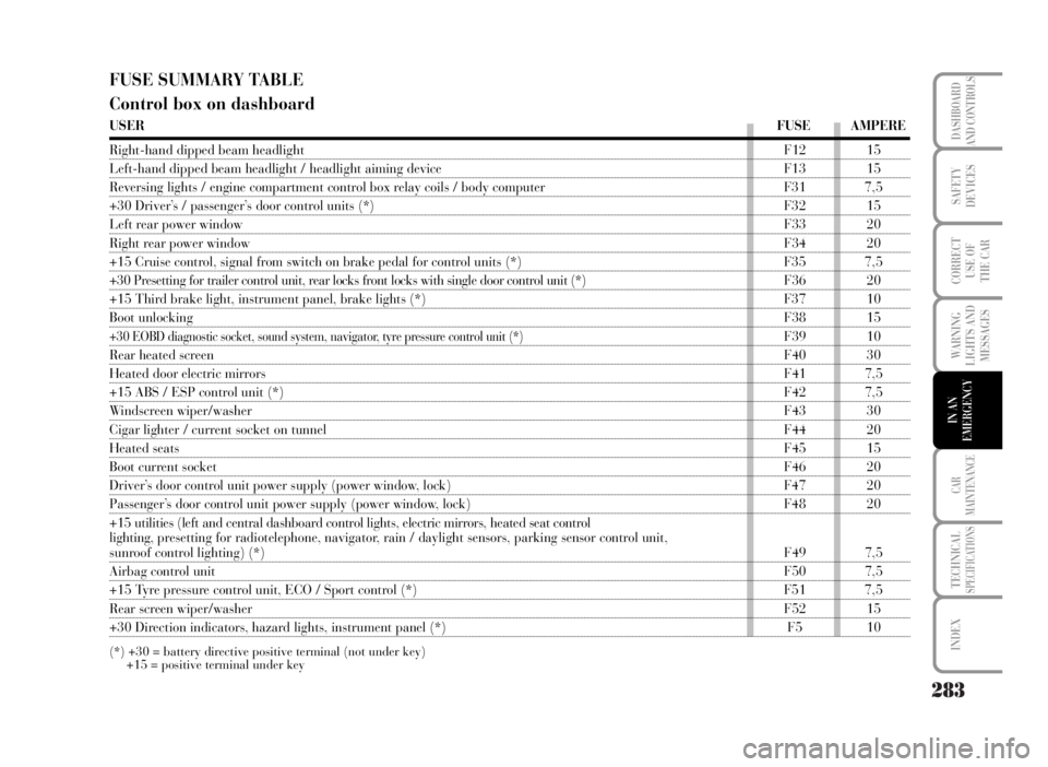
FUSE SUMMARY TABLE
Control box on dashboard
USERFUSE AMPERE
Right-hand dipped beam headlightF12 15
Left-hand dipped beam headlight / headlight aiming device F13 15
Reversing lights / engine compartment control box relay coils / body computer F31 7,5
+30 Driver’s / passenger’s door control units (*) F32 15
Left rear power windowF33 20
Right rear power windowF34 20
+15 Cruise control, signal from switch on brake pedal for control units (*) F35 7,5
+30 Presetting for trailer control unit, rear locks front locks with single door control unit (*) F36 20
+15 Third brake light, instrument panel, brake lights (*) F37 10
Boot unlockingF38 15
+30 EOBD diagnostic socket, sound system, navigator, tyre pressure control unit (*)F39 10
Rear heated screenF40 30
Heated door electric mirrorsF41 7,5
+15 ABS / ESP control unit (*)F42 7,5
Windscreen wiper/washerF43 30
Cigar lighter / current socket on tunnelF44 20
Heated seatsF45 15
Boot current socketF46 20
Driver’s door control unit power supply (power window, lock) F47 20
Passenger’s door control unit power supply (power window, lock) F48 20
+15 utilities (left and central dashboard control lights, electric mirrors, heated seat control
lighting, presetting for radiotelephone, navigator, rain / daylight sensors, parking sensor control unit,
sunroof control lighting) (*)F49 7,5
Airbag control unitF50 7,5
+15 Tyre pressure control unit, ECO / Sport control (*) F51 7,5
Rear screen wiper/washerF52 15
+30 Direction indicators, hazard lights, instrument panel (*) F5 10
(*) +30 = battery directive positive terminal (not under key)
+15 = positive terminal under key
Page 285 of 346

284
WARNING
LIGHTS AND
MESSAGES
CAR
MAINTENANCE
TECHNICALSPECIFICATIONS
INDEX
DASHBOARD
AND CONTROLS
SAFETY
DEVICES
CORRECT
USE OF
THE CAR
IN AN
EMERGENCY
Fuse box in engine compartment
USERFUSE AMPERE
Dashboard control unit 1F1 70
Power steering control unitF2 70
Ignition switchF3 20
Dashboard control unit 2F4 50
ABS / ESP control unitF5 60
Radiator electric fan (low speed) (all versions)F6 30
Radiator electric fan (high speed) (all versions excluded 1.4 16V heated) F7 40
Climate control electric fanF8 30
Headlight washerF9 20
HornF10 15
Electronic injection secondary servicesF11 15
Right main beam headlightF14 10
Left main beam headlightF15 10
Electronic injection primary servicesF17 10
+30 Engine control unit / Radiator electric fan remote control switch (1.9 Multijet) (*) F18 7,5
CompressorF19 7,5
Heated diesel oil filter (Multijet)F20 30
Fuel pumpF21 15
Electronic injection primary services (1.4 16V)F22 15
Electronic injection primary services (Multijet)F22 20
Dual FuNction System gearbox oil pumpF23 15
Dual FuNction System gearbox fuse box power supply (+ key) F16 7,5
+15 Electric power steering (*)F24 7,5
Front fog lightsF30 15
(*) +30 = battery directive positive terminal (not under key)
+15 = positive terminal under key
Page 286 of 346

285
WARNING
LIGHTS AND
MESSAGES
CAR
MAINTENANCE
TECHNICALSPECIFICATIONS
INDEX
DASHBOARD
AND CONTROLS
SAFETY
DEVICES
CORRECT
USE OF
THE CAR
IN AN
EMERGENCY
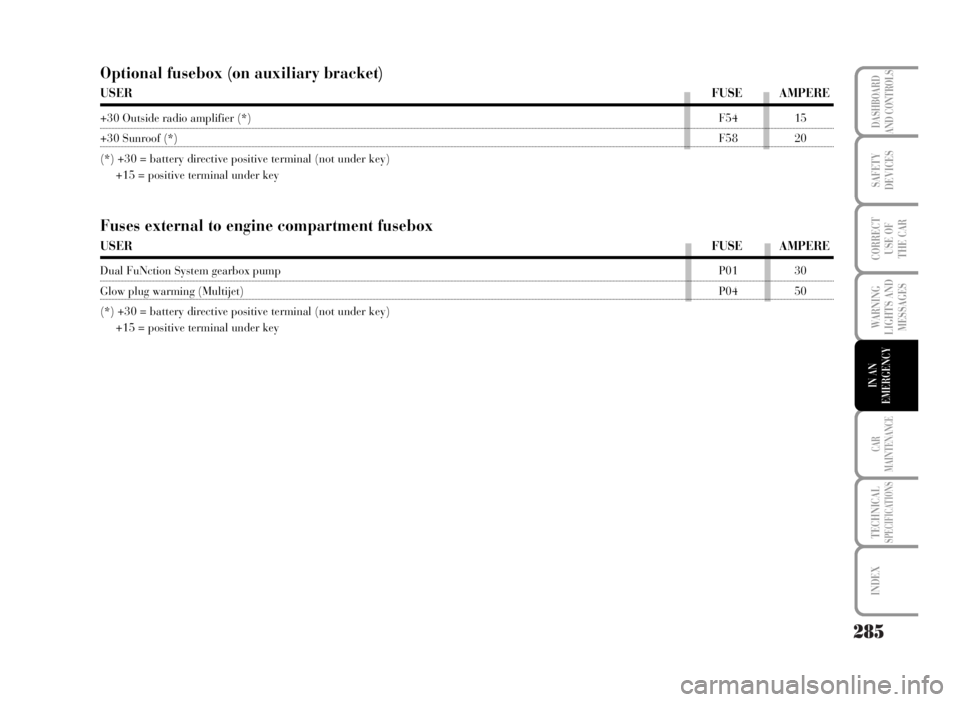
Fuses external to engine compartment fusebox
USERFUSE AMPERE
Dual FuNction System gearbox pumpP01 30
Glow plug warming (Multijet)P04 50
(*) +30 = battery directive positive terminal (not under key)
+15 = positive terminal under key
Optional fusebox (on auxiliary bracket)
USERFUSE AMPERE
+30 Outside radio amplifier (*)F54 15
+30 Sunroof (*)F58 20
(*) +30 = battery directive positive terminal (not under key)
+15 = positive terminal under key
Page 287 of 346

286
WARNING
LIGHTS AND
MESSAGES
CAR
MAINTENANCE
TECHNICALSPECIFICATIONS
INDEX
DASHBOARD
AND CONTROLS
SAFETY
DEVICES
CORRECT
USE OF
THE CAR
IN AN
EMERGENCY
IF THE BATTERY IS FLAT
WARNING The battery charging procedure is
described only for information purposes. This
operation should be carried out by Lancia
Dealership.
Charging should be slow at low amp rating for 24
hours. Charging for a longer time may damage the
battery.
Charge the battery as follows:
❒disconnect battery negative terminal;❒connect the charger cables to the battery
terminals, observing the poles;
❒turn on the charger;
❒when you have finished, turn the charger off
before disconnecting the battery;
❒reconnect battery negative terminal.
WARNING If the vehicle is fitted with alarm system,
turn it off with the remote control (see “Alarm” in
the “Dashboard and controls” chapter).
The liquid in the battery is poisonous and corrosive. Do not let it touch the skin or
eyes. Recharging the battery should be done in a well ventilated area away from
naked flames or possible sources of sparks: explosion and fire risk.
WARNING
WARNING
Do not attempt to recharge a frozen battery. Thaw it first, otherwise it could
explode. If the battery froze, make sure the internal elements are not broken
(short-circuit risk) and that the casing is not cracked (risk of spilling the
poisonous and corrosive fluid).