ECU LAND ROVER DISCOVERY 2002 Workshop Manual
[x] Cancel search | Manufacturer: LAND ROVER, Model Year: 2002, Model line: DISCOVERY, Model: LAND ROVER DISCOVERY 2002Pages: 1672, PDF Size: 46.1 MB
Page 548 of 1672
FUEL DELIVERY SYSTEM - TD5
DESCRIPTION AND OPERATION 19-1-3
Description
General
The fuel delivery system comprises a fuel tank, fuel pump, fuel pressure regulator, five injectors and a fuel filter. The
system is controlled by the Engine Control Module (ECM) which energises the fuel pump relay and controls the
operation and timing of each injector solenoid.
Unlike other Diesel engines, the Td5 engine has no injection pump. The diesel direct injection system receives fuel
at pressure from a two stage fuel pump located in the fuel tank. The system incorporates a fuel return to the fuel pump,
via a fuel cooler attached to the inlet manifold and a fuel filter. A fuel pressure regulator is located in a housing on the
rear of the cylinder head. The regulator maintains the fuel delivered to the injectors at a constant pressure and returns
excess fuel back to the fuel filter and pump via the fuel cooler.
A fuel filter is positioned on the chassis to the right of the fuel tank. The fuel feed and return to and from the engine
passes through the filter. The filter also incorporates a water sensor which illuminates a warning lamp in the
instrument pack.
A moulded fuel tank is located at the rear underside of the vehicle between the chassis longitudinals. The tank
provides the attachment for the fuel pump and fuel gauge sender unit which is located inside the tank.
Fuel tank and breather
The fuel tank and breather system is a major part of the fuel delivery system. The fuel tank and breathers are located
at the rear of the vehicle between the chassis longitudinals.
Fuel tank
The moulded fuel tank is made from High Molecular Weight (HMW) High Density Polyethylene (HDPE). The diesel
tank is manufactured using a proportion of recycled plastic.
The tank is retained in position by a metal cradle which is secured to the chassis with two nut plates and bolts at the
rear and a stud plate and two nuts at the front. A strap above the tank is bolted to the chassis and restrains the tank
from moving upwards. The fuel tank has useable capacity of approximately 95 litres (25 US Gallons).
An aperture in the top surface of the tank allows for the fitment of the fuel pump and fuel gauge sender unit which is
retained with a locking ring.
A reflective metallic covering is attached to the tank with two scrivets to shield the tank from heat generated by the
exhaust system.
The fuel filler is located in the right hand rear quarter panel, behind an access flap. The flap is opened electrically
using a switch on the fascia which operates a release solenoid.
The filler is closed by a threaded plastic cap which screws into the filler neck. The cap has a ratchet mechanism to
prevent overtightening and seals against the filler neck to prevent the escape of fuel vapour. The filler cap has a valve
which relieves fuel pressure to atmosphere at approximately 0.12 to 0.13 bar (1.8 to 2.0 lbf.in
2) and opens in the
opposite direction at approximately 0.04 bar (0.7 lbf.in2) vacuum.
A moulded filler tube, made from HMW HDPE, connects the filler to the tank via a flexible hose. The filler tube is
connected at its top end behind the filler flap.
Page 550 of 1672
FUEL DELIVERY SYSTEM - TD5
DESCRIPTION AND OPERATION 19-1-5
The fuel pump is a 'self priming', wet type, two stage pump which is immersed in fuel in the tank and operates at all
times when the ignition switch is in position II. If the engine is not started, the ECU will 'time-out' after three minutes
and de-energise the fuel pump relay. The pump receives a feed from the battery via fuse 10 in the engine
compartment fusebox and the fuel pump relay. The relay is energised by the ECM when the ignition switch is moved
to position II.
The fuel pump assembly is retained with a locking ring and sealed with a rubber seal. The locking ring requires a
special tool for removal and refitment. An access panel for the fuel pump is located in the loadspace floor below the
carpet. The access panel is sealed to the floor with a rubber seal and retained by six self-tapping screws. A four pin
electrical connector is located on the top cover and provides power feed and earth for the fuel pump and also inputs
and outputs for the fuel gauge sender operation.
The fuel gauge sender is integral with the fuel pump. The sender is submerged in the fuel and is operated by a float
which moves with the fuel level in the tank.
Fuel pump
The fuel pump assembly comprises a top cover which locates the electrical connector, fuel burning heater connection
and four fuel pipe couplings. The top cover is attached to a plastic cup shaped housing and retained on three sliding
clips. Two coil springs are located between the cover and the housing and ensure that the fuel pump remains seated
positively at the bottom of the tank when installed.
The housing locates the two stage fuel pump and also the fuel gauge sender unit. The lower part of the housing is the
swirl pot which maintains a constant level of fuel at the fuel pick-up. A coarse filter is located in the base of the housing
and prevents the ingress of contaminants into the pump and the fuel system from the fuel being drawn into the pump.
A fine filter is located in the intake to the low pressure stage to protect the pump from contaminants. Flexible pipes
connect the couplings on the top cover to the pump.
A non-return valve is located in the base of the housing. When the fuel tank is full, fuel pressure keeps the valve lifted
from its seat allowing fuel to flow into the swirl pot. As the tank level reduces, the fuel pressure in the tank reduces
causing the valve to close. When the valve is closed fuel is retained in the swirl pot, ensuring that the swirl pot remains
full and maintains a constant supply to the fuel pump.
The two stage pump comprises a high and a low pressure stage. The low pressure stage draws fuel from the swirl
pot through the filter. The low pressure stage pumps fluid at a pressure of 0.75 bar (10.9 lbf.in
2) and a flow of 30 litres/
hour (8 US Gallons/hour) to the fuel filter. A proportion of the fuel from the low pressure stage also passes, via a
restrictor, through a jet pump which keeps fuel circulating in the swirl pot. The high pressure stage draws the low
pressure fuel from the fuel filter and pressurises it to a pressure of 4.0 bar (58 lbf.in
2). The pressurised fuel is then
passed from the pump to the injectors at a flow of 180 litres/hour (47.6 US Gallons/hour). A fuel pressure regulator is
located at the rear of the engine and ensures that the delivery pressure remains at 4.0 bar (58 lbf.in
2) by controlling
the amount of fuel returning to the fuel tank.
The fuel pump has a maximum current draw of 15 Amps at 12.5 V and is protected by a 20 Amp fuse in the engine
compartment fusebox.
Page 552 of 1672
FUEL DELIVERY SYSTEM - TD5
DESCRIPTION AND OPERATION 19-1-7
The fuel pressure regulator is located in a cast alloy housing which is attached to the rear right hand corner of the
cylinder head with three flanged bolts and sealed with a metal gasket. On pre EU3 models there are two ports in the
housing that connect with ports in the cylinder head for fuel pressure feed and return. On EU3 models there is a port
in the housing that connects with a port in the cylinder head for fuel pressure feed and a single external port for fuel
return. A gauze filter is located in the pressure feed port in the cylinder head and filters the fuel before it reaches the
injectors. The filter is a fit for life item but can be changed if required. An 'O' ring is located in a recess in the cylinder
head and provides additional sealing for the pressure feed port between the gauze filter, the cylinder head and the
housing.
A union and pipe is attached to the feed port in the housing and connects with a quick release coupling to the fuel
pressure feed pipe from the fuel pump. A second union and hose is located in the return port and provides the fuel
return connection to the fuel cooler. A third port provides location for the fuel temperature sensor which is sealed to
the housing with a bonded seal. The fuel temperature sensor is used by the Engine Control Module (ECM) for engine
management.
The fuel pressure regulator is located in a machined port in the lower part of the housing. The regulator is sealed in
the housing with two 'O' rings and secured with an internal circlip.
The regulator maintains the fuel pump delivery pressure at 4 bar (58 lbf.in
2). When the fuel pressure exceeds 4 bar
(58 lbf.in2), the regulator opens and allows fuel to return to the fuel tank via the fuel cooler. The fuel returned from the
regulator is directed back into the fuel filter before being drawn by the high pressure stage of the fuel pump and
directed back to the injectors. A special tool can be attached to the regulator housing fuel feed port and allows for the
fitment of a suitable gauge to measure fuel pump delivery pressure.
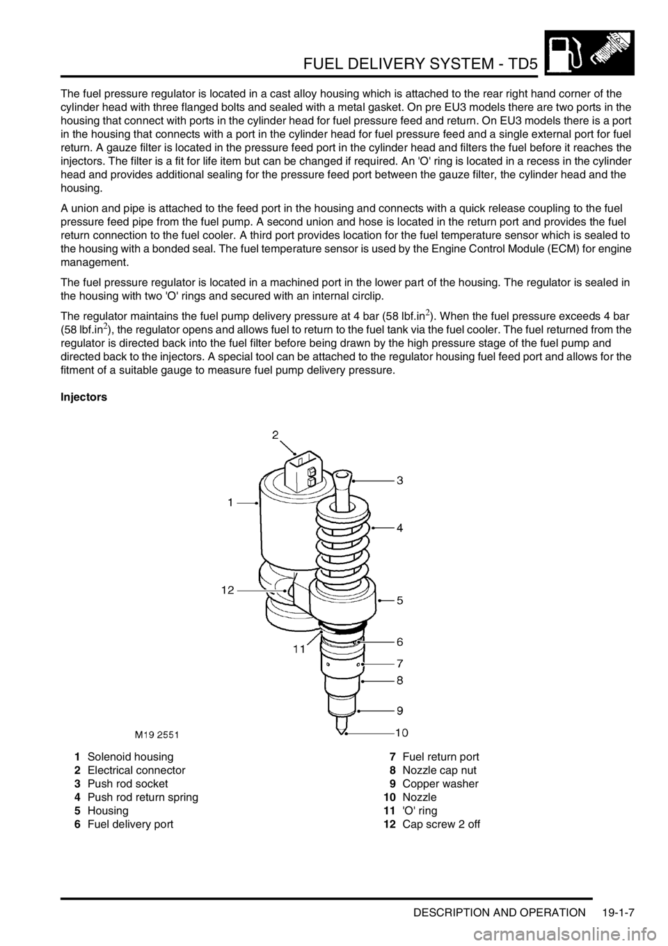
Injectors
1Solenoid housing
2Electrical connector
3Push rod socket
4Push rod return spring
5Housing
6Fuel delivery port7Fuel return port
8Nozzle cap nut
9Copper washer
10Nozzle
11'O' ring
12Cap screw 2 off
Page 553 of 1672

FUEL DELIVERY SYSTEM - TD5
19-1-8 DESCRIPTION AND OPERATION
The five injectors are located in the cylinder head, adjacent to the camshaft, with the nozzle of each injector protruding
directly into the cylinder. Each injector is sealed into the cylinder head with an 'O' ring and a copper washer and
secured with a clamp and bolt.
Each injector is operated mechanically by an overhead camshaft and rocker and electrically by a solenoid controlled
by the ECM. Each injector is supplied with pressurised fuel from the pump via the regulator housing and internal
drillings in the cylinder head.
+ ENGINE MANAGEMENT SYSTEM - Td5, DESCRIPTION AND OPERATION, Description.
The solenoid housing is secured to the injector body with two cap screws and is a sealed unit with a two pin electrical
connector on its top face.
The injector body is machined from a forging. The body has a machined central bore which locates the push rod. A
thread on the outer diameter provides the attachment for the nozzle cap nut. The body also provides attachment for
the solenoid housing.
The injector push rod is operated from the rocker and cam assembly by a socket. The push rod is located in the
housing bore and retained in its extended position by a push rod return spring. The powerful spring ensures that the
push rod socket is always in contact with the rocking lever and the cam.
The lower part of the injector housing locates the spring loaded nozzle. The nozzle is retained in the housing by a
nozzle cap nut which is screwed onto the housing. The nozzle cap nut has four holes around its circumference which
connect to the fuel return drilling in the cylinder head. The injector housing has ports located above the nozzle cap
nut which connect with the fuel delivery drilling in the cylinder head. An 'O' ring seals the injector in the machined
location in the cylinder head and a copper washer seals the injector from the combustion chamber.
The injectors are supplied with pressurised fuel from the fuel pump, via the pressure regulator housing and internal
drillings in the cylinder head. Each injector sprays fuel directly into the cylinder at approximately, 1500 bar (22000
lbf.in
2) on pre EU3 models and 1750 bar (25500 lbf.in2) on EU3 models, atomising the fuel and mixing it with intake
air prior to combustion.
The camshaft and rocker arrangement depresses the push rod which pressurises the fuel within the injector. When
the injector is required to inject fuel into the cylinder, the ECM energises the solenoid which closes a valve within the
solenoid housing. The closure of the valve stops the fuel entering the return line to the pump, trapping it in the injector.
The compression of the fuel by the push rod causes rapid pressurisation of the fuel which lifts the injector nozzle,
forcing the fuel into the cylinder at high pressure. The ECM controls the injection timing by altering the time at which
the solenoid is energised and the injection period by controlling the period for which the solenoid is energised.
+ ENGINE MANAGEMENT SYSTEM - Td5, DESCRIPTION AND OPERATION, Description.
Page 560 of 1672
FUEL DELIVERY SYSTEM - TD5
REPAIRS 19-1-15
REPAIRS
Switch - inertia - fuel cut-off
$% 19.22.09
Remove
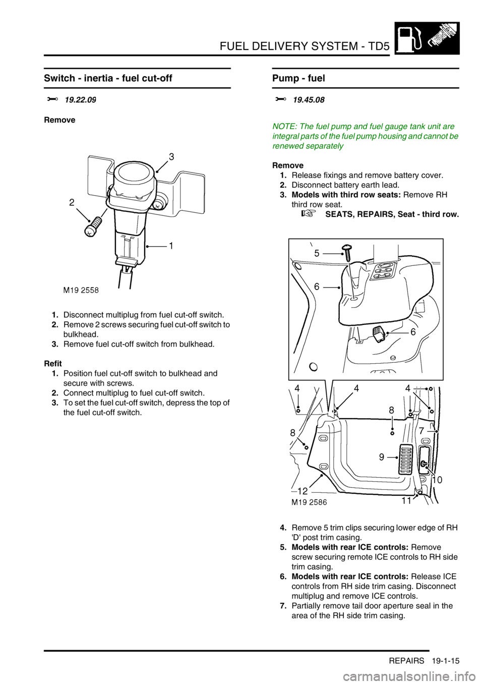
1.Disconnect multiplug from fuel cut-off switch.
2.Remove 2 screws securing fuel cut-off switch to
bulkhead.
3.Remove fuel cut-off switch from bulkhead.
Refit
1.Position fuel cut-off switch to bulkhead and
secure with screws.
2.Connect multiplug to fuel cut-off switch.
3.To set the fuel cut-off switch, depress the top of
the fuel cut-off switch.
Pump - fuel
$% 19.45.08
NOTE: The fuel pump and fuel gauge tank unit are
integral parts of the fuel pump housing and cannot be
renewed separately
Remove
1.Release fixings and remove battery cover.
2.Disconnect battery earth lead.
3. Models with third row seats: Remove RH
third row seat.
+ SEATS, REPAIRS, Seat - third row.
4.Remove 5 trim clips securing lower edge of RH
'D' post trim casing.
5. Models with rear ICE controls: Remove
screw securing remote ICE controls to RH side
trim casing.
6. Models with rear ICE controls: Release ICE
controls from RH side trim casing. Disconnect
multiplug and remove ICE controls.
7.Partially remove tail door aperture seal in the
area of the RH side trim casing.
Page 561 of 1672
FUEL DELIVERY SYSTEM - TD5
19-1-16 REPAIRS
8.Remove 2 trim clips securing RH side trim
casing to body.
9.Remove rear lamp access panel from RH side
trim casing.
10.Remove trim clip securing RH side trim casing
to lower 'E' post.
11. Models with third row seats:Remove bolt
securing lower mounting of RH third row seat
belt to body.
12.Remove RH side trim casing.
13.Pull back loadspace carpet from fuel pump
access panel.
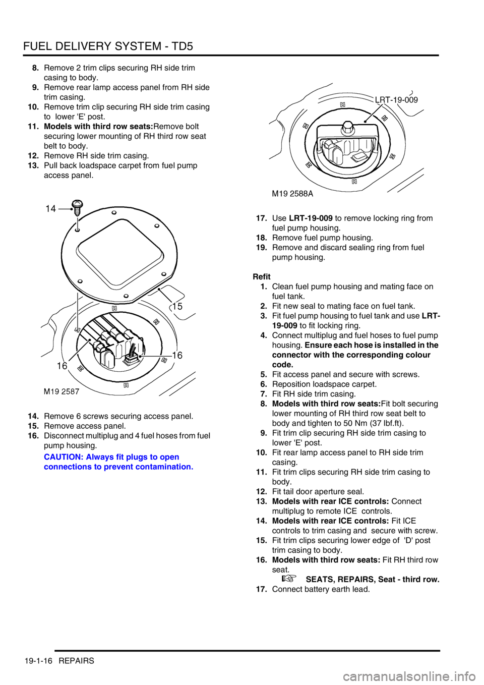
14.Remove 6 screws securing access panel.
15.Remove access panel.
16.Disconnect multiplug and 4 fuel hoses from fuel
pump housing.
CAUTION: Always fit plugs to open
connections to prevent contamination.17.Use LRT-19-009 to remove locking ring from
fuel pump housing.
18.Remove fuel pump housing.
19.Remove and discard sealing ring from fuel
pump housing.
Refit
1.Clean fuel pump housing and mating face on
fuel tank.
2.Fit new seal to mating face on fuel tank.
3.Fit fuel pump housing to fuel tank and use LRT-
19-009 to fit locking ring.
4.Connect multiplug and fuel hoses to fuel pump
housing. Ensure each hose is installed in the
connector with the corresponding colour
code.
5.Fit access panel and secure with screws.
6.Reposition loadspace carpet.
7.Fit RH side trim casing.
8. Models with third row seats:Fit bolt securing
lower mounting of RH third row seat belt to
body and tighten to 50 Nm (37 lbf.ft).
9.Fit trim clip securing RH side trim casing to
lower 'E' post.
10.Fit rear lamp access panel to RH side trim
casing.
11.Fit trim clips securing RH side trim casing to
body.
12.Fit tail door aperture seal.
13. Models with rear ICE controls: Connect
multiplug to remote ICE controls.
14. Models with rear ICE controls: Fit ICE
controls to trim casing and secure with screw.
15.Fit trim clips securing lower edge of 'D' post
trim casing to body.
16. Models with third row seats: Fit RH third row
seat.
+ SEATS, REPAIRS, Seat - third row.
17.Connect battery earth lead.
Page 562 of 1672
FUEL DELIVERY SYSTEM - TD5
REPAIRS 19-1-17
Tank - fuel
$% 19.55.01
Remove
1.Drain fuel tank.
+ FUEL DELIVERY SYSTEM - Td5,
ADJUSTMENTS, Fuel tank - drain.
2.Raise rear of vehicle.
WARNING: Do not work on or under a
vehicle supported only by a jack. Always
support the vehicle on safety stands.
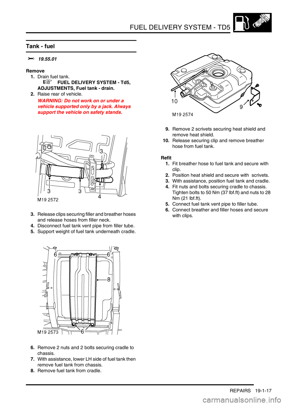
3.Release clips securing filler and breather hoses
and release hoses from filler neck.
4.Disconnect fuel tank vent pipe from filler tube.
5.Support weight of fuel tank underneath cradle.
6.Remove 2 nuts and 2 bolts securing cradle to
chassis.
7.With assistance, lower LH side of fuel tank then
remove fuel tank from chassis.
8.Remove fuel tank from cradle.9.Remove 2 scrivets securing heat shield and
remove heat shield.
10.Release securing clip and remove breather
hose from fuel tank.
Refit
1.Fit breather hose to fuel tank and secure with
clip.
2.Position heat shield and secure with scrivets.
3.With assistance, position fuel tank and cradle.
4.Fit nuts and bolts securing cradle to chassis.
Tighten bolts to 50 Nm (37 lbf.ft) and nuts to 28
Nm (21 lbf.ft).
5.Connect fuel tank vent pipe to filler tube.
6.Connect breather and filler hoses and secure
with clips.
Page 563 of 1672
FUEL DELIVERY SYSTEM - TD5
19-1-18 REPAIRS
Solenoid - fuel filler flap release
$% 19.55.17
Remove
1.Remove loadspace RH side trim casing.
+ INTERIOR TRIM COMPONENTS,
REPAIRS, Trim casing - side - loadspace.
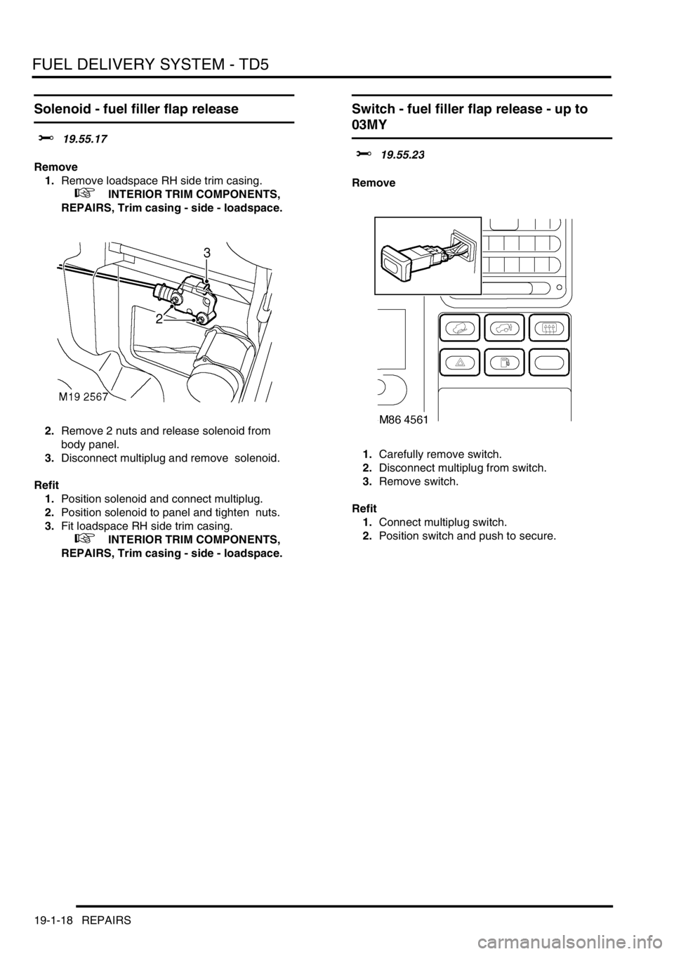
2.Remove 2 nuts and release solenoid from
body panel.
3.Disconnect multiplug and remove solenoid.
Refit
1.Position solenoid and connect multiplug.
2.Position solenoid to panel and tighten nuts.
3.Fit loadspace RH side trim casing.
+ INTERIOR TRIM COMPONENTS,
REPAIRS, Trim casing - side - loadspace.
Switch - fuel filler flap release - up to
03MY
$% 19.55.23
Remove
1.Carefully remove switch.
2.Disconnect multiplug from switch.
3.Remove switch.
Refit
1.Connect multiplug switch.
2.Position switch and push to secure.
Page 564 of 1672
FUEL DELIVERY SYSTEM - TD5
REPAIRS 19-1-19
Switch - fuel filler flap release - from
03MY
$% 19.55.23
Remove
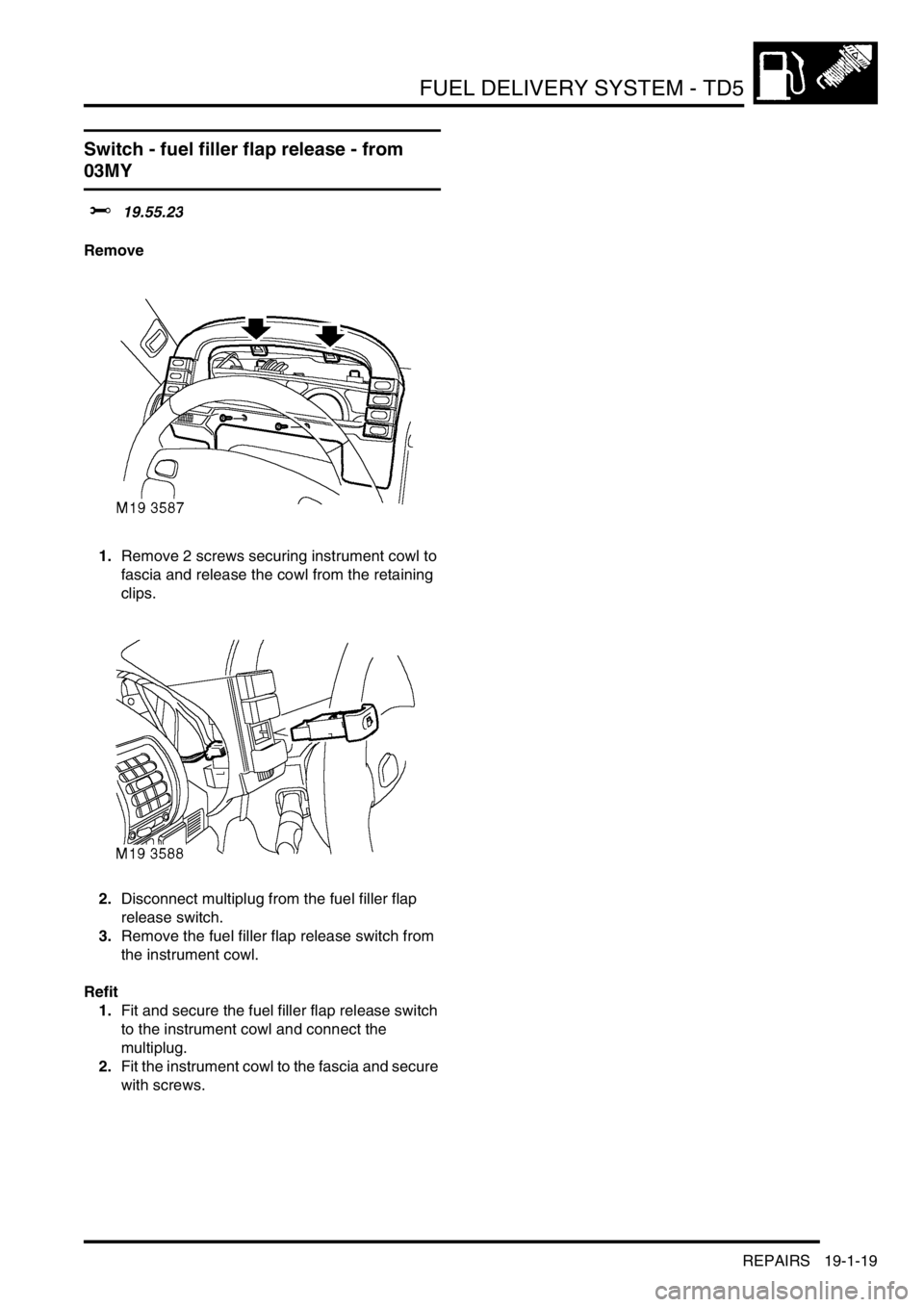
1.Remove 2 screws securing instrument cowl to
fascia and release the cowl from the retaining
clips.
2.Disconnect multiplug from the fuel filler flap
release switch.
3.Remove the fuel filler flap release switch from
the instrument cowl.
Refit
1.Fit and secure the fuel filler flap release switch
to the instrument cowl and connect the
multiplug.
2.Fit the instrument cowl to the fascia and secure
with screws.
Page 569 of 1672
FUEL DELIVERY SYSTEM - V8
19-2-4 DESCRIPTION AND OPERATION
Description
General
The fuel delivery system comprises a fuel tank, fuel pump and regulator and eight injectors. The system is controlled
by the Engine Control Module (ECM) which energises the fuel pump relay and controls the operation and timing of
each injector solenoid.
+ ENGINE MANAGEMENT SYSTEM - V8, DESCRIPTION AND OPERATION, Description - engine
management.
The multiport fuel injection system is a returnless system with the fuel pressure maintained at a constant level by a
fuel pressure regulator. The regulator is located in the fuel pump housing and returns excess fuel directly from the
pump to the tank.
An electrically operated fuel pump is located in the top of the fuel tank and supplies fuel at pressure to two fuel rails
via a flexible hose. The hose is attached to the feed pipe on the fuel rail at the rear of the engine and the fuel pump
with sealed quick release couplings.
A moulded fuel tank is located at the rear underside of the vehicle between the chassis longitudinals. The tank
provides the attachment for the fuel pump and fuel gauge sender unit which is located inside the tank. The fuel system
is pressurised permanently with pressurised fuel vapour venting to an EVAP canister.
+ EMISSION CONTROL - V8, DESCRIPTION AND OPERATION, Emission Control Systems.
Fuel tank and breather
The fuel tank and breather system is a major part of the fuel delivery system. The fuel tank and breathers are located
at the rear of the vehicle between the chassis longitudinals.
Fuel tank
The moulded fuel tank is made from High Molecular Weight (HMW) High Density Polyethylene (HDPE). Continuous
layers of nylon additive are used during the moulding process. The nylon layers give an improved limit of fuel
permeation through the tank wall and are also resistant to alcohol based fuels used in the NAS market.
The tank is retained in position by a metal cradle which is secured to the chassis with two nut plates and bolts at the
rear and a stud plate and two nuts at the front. A strap above the tank is bolted to the chassis and restrains the tank
from moving upwards. The fuel tank has a useable capacity of approximately 95 litres (25 US Gallons).
An aperture in the top surface of the tank allows for the fitment of the fuel pump, regulator and fuel gauge sender unit
which is retained with a locking ring.
A reflective metallic covering is attached to the tank with two scrivets to shield the tank from heat generated by the
exhaust system.
The fuel filler is located in the right hand rear quarter panel, behind an access flap. The flap is opened electrically
using a switch on the fascia.
The filler is closed by a threaded plastic cap which screws into the filler neck. The cap has a ratchet mechanism to
prevent over tightening and seals against the filler neck to prevent the escape of fuel vapour. The filler cap has a valve
which relieves fuel pressure to atmosphere at approximately 0.12 to 0.13 bar (1.8 to 2.0 lbf.in
2) and opens in the
opposite direction at approximately 0.04 bar (0.7 lbf.in2) vacuum.
All markets except NAS: A moulded filler tube, made from HMW HDPE with no additional additives, connects the
filler to the tank via a flexible rubber hose. The filler tube is connected at its top end behind the filler flap.