LAND ROVER FREELANDER 2001 Workshop Manual
Manufacturer: LAND ROVER, Model Year: 2001, Model line: FREELANDER, Model: LAND ROVER FREELANDER 2001Pages: 1007, PDF Size: 23.47 MB
Page 601 of 1007
RESTRAINT SYSTEMS
75-20 REPAIRS
Airbag module - steering wheel -
deployment - off vehicle
$% 76.74.16
These guidelines are written to aid authorised
personnel to carry out the safe disposal of airbag
modules when removed from the vehicle.
Deploy
WARNING: It is imperative that before any
work is undertaken on the SRS system, the
appropriate information is read thoroughly.
1.Make the SRS system safe.
+ GENERAL INFORMATION, SRS
component manual deployment.
2.Remove airbag module from steering wheel.
+ RESTRAINT SYSTEMS, REPAIRS,
Air bag - steering wheel.
3.Check condition of deployment tool LRT-86-
003 and associated flyleads.
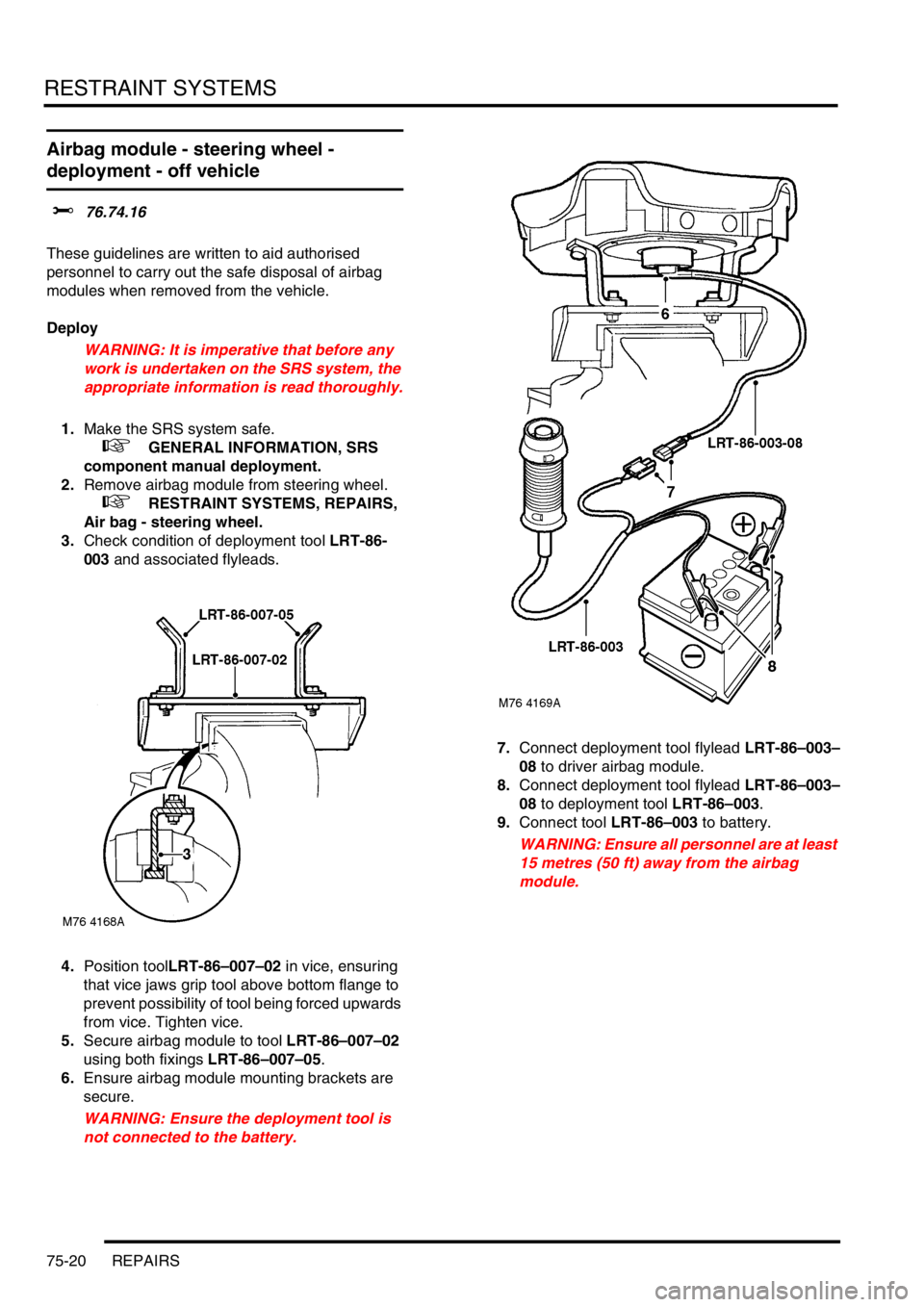
4.Position toolLRT-86–007–02 in vice, ensuring
that vice jaws grip tool above bottom flange to
prevent possibility of tool being forced upwards
from vice. Tighten vice.
5.Secure airbag module to tool LRT-86–007–02
using both fixings LRT-86–007–05.
6.Ensure airbag module mounting brackets are
secure.
WARNING: Ensure the deployment tool is
not connected to the battery.7.Connect deployment tool flylead LRT-86–003–
08 to driver airbag module.
8.Connect deployment tool flylead LRT-86–003–
08 to deployment tool LRT-86–003.
9.Connect tool LRT-86–003 to battery.
WARNING: Ensure all personnel are at least
15 metres (50 ft) away from the airbag
module.
Page 602 of 1007
RESTRAINT SYSTEMS
REPAIRS 75-21
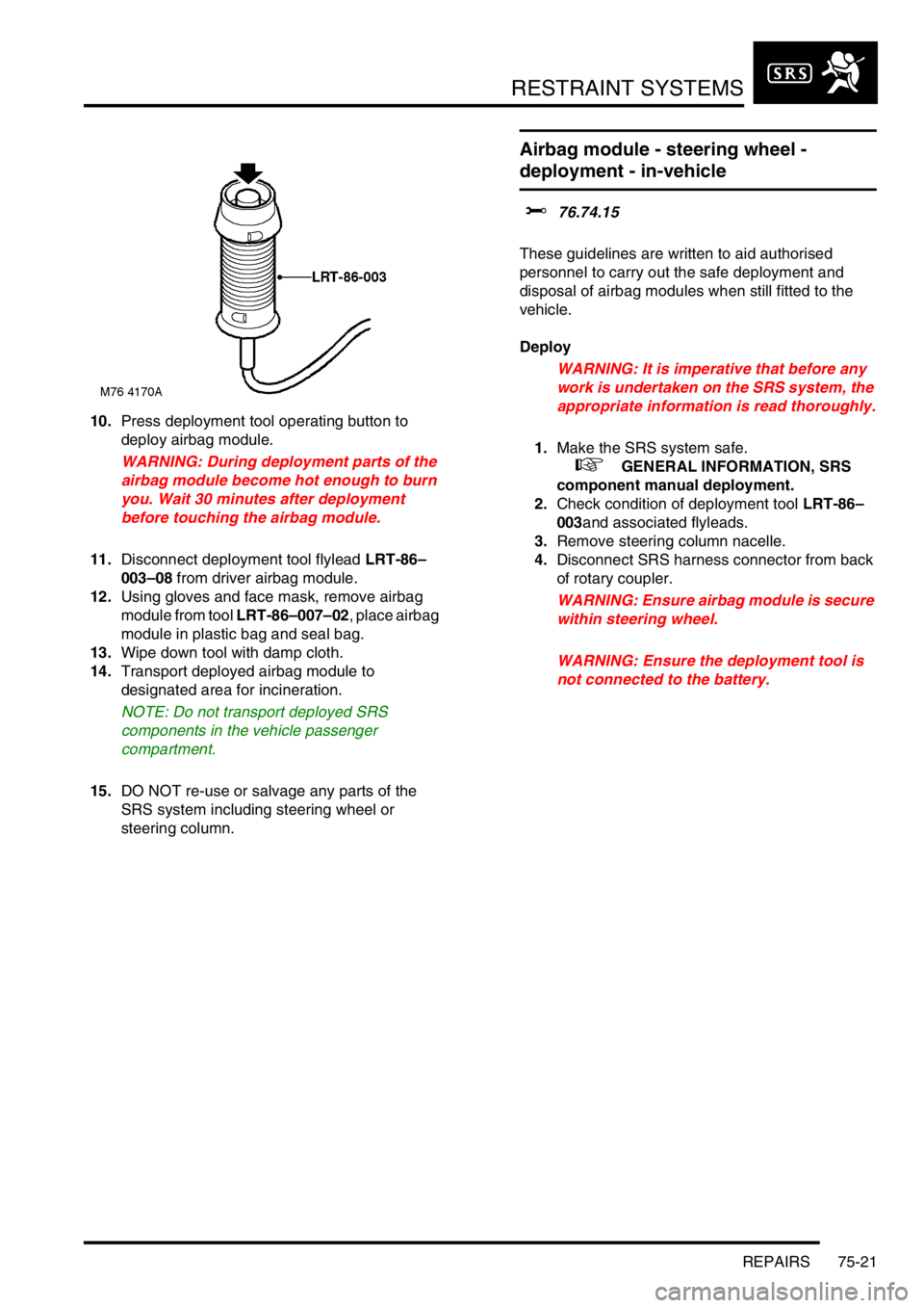
10.Press deployment tool operating button to
deploy airbag module.
WARNING: During deployment parts of the
airbag module become hot enough to burn
you. Wait 30 minutes after deployment
before touching the airbag module.
11.Disconnect deployment tool flylead LRT-86–
003–08 from driver airbag module.
12.Using gloves and face mask, remove airbag
module from tool LRT-86–007–02, place airbag
module in plastic bag and seal bag.
13.Wipe down tool with damp cloth.
14.Transport deployed airbag module to
designated area for incineration.
NOTE: Do not transport deployed SRS
components in the vehicle passenger
compartment.
15.DO NOT re-use or salvage any parts of the
SRS system including steering wheel or
steering column.
Airbag module - steering wheel -
deployment - in-vehicle
$% 76.74.15
These guidelines are written to aid authorised
personnel to carry out the safe deployment and
disposal of airbag modules when still fitted to the
vehicle.
Deploy
WARNING: It is imperative that before any
work is undertaken on the SRS system, the
appropriate information is read thoroughly.
1.Make the SRS system safe.
+ GENERAL INFORMATION, SRS
component manual deployment.
2.Check condition of deployment tool LRT-86–
003and associated flyleads.
3.Remove steering column nacelle.
4.Disconnect SRS harness connector from back
of rotary coupler.
WARNING: Ensure airbag module is secure
within steering wheel.
WARNING: Ensure the deployment tool is
not connected to the battery.
Page 603 of 1007
RESTRAINT SYSTEMS
75-22 REPAIRS
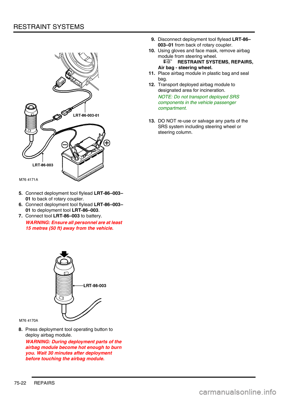
5.Connect deployment tool flylead LRT-86–003–
01 to back of rotary coupler.
6.Connect deployment tool flylead LRT-86–003–
01 to deployment tool LRT-86–003.
7.Connect tool LRT-86–003 to battery.
WARNING: Ensure all personnel are at least
15 metres (50 ft) away from the vehicle.
8.Press deployment tool operating button to
deploy airbag module.
WARNING: During deployment parts of the
airbag module become hot enough to burn
you. Wait 30 minutes after deployment
before touching the airbag module.9.Disconnect deployment tool flylead LRT-86–
003–01 from back of rotary coupler.
10.Using gloves and face mask, remove airbag
module from steering wheel.
+ RESTRAINT SYSTEMS, REPAIRS,
Air bag - steering wheel.
11.Place airbag module in plastic bag and seal
bag.
12.Transport deployed airbag module to
designated area for incineration.
NOTE: Do not transport deployed SRS
components in the vehicle passenger
compartment.
13.DO NOT re-use or salvage any parts of the
SRS system including steering wheel or
steering column.
Page 604 of 1007
RESTRAINT SYSTEMS
REPAIRS 75-23
Pre-tensioner - front seatbelt -
deployment - in-vehicle
$% 76.73.77
These guidelines are written to aid authorised
personnel to carry out the safe deployment and
disposal of seatbelt pre-tensioners when they are still
fitted in the vehicle.
Deploy
WARNING: It is imperative that before any
work is undertaken on the SRS system, the
appropriate information is read thoroughly.
1.Make the SRS system safe.
+ GENERAL INFORMATION, SRS
component manual deployment.
2.Check condition of deployment toolLRT-86–
003 and associated flyleads.
3.Slide seat fully rearwards to access pre-
tensioner harness connector.
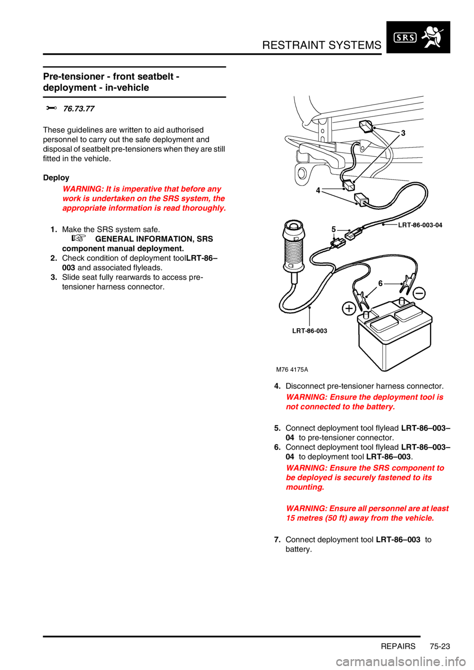
4.Disconnect pre-tensioner harness connector.
WARNING: Ensure the deployment tool is
not connected to the battery.
5.Connect deployment tool flylead LRT-86–003–
04 to pre-tensioner connector.
6.Connect deployment tool flylead LRT-86–003–
04 to deployment tool LRT-86–003.
WARNING: Ensure the SRS component to
be deployed is securely fastened to its
mounting.
WARNING: Ensure all personnel are at least
15 metres (50 ft) away from the vehicle.
7.Connect deployment tool LRT-86–003 to
battery.
Page 605 of 1007
RESTRAINT SYSTEMS
75-24 REPAIRS
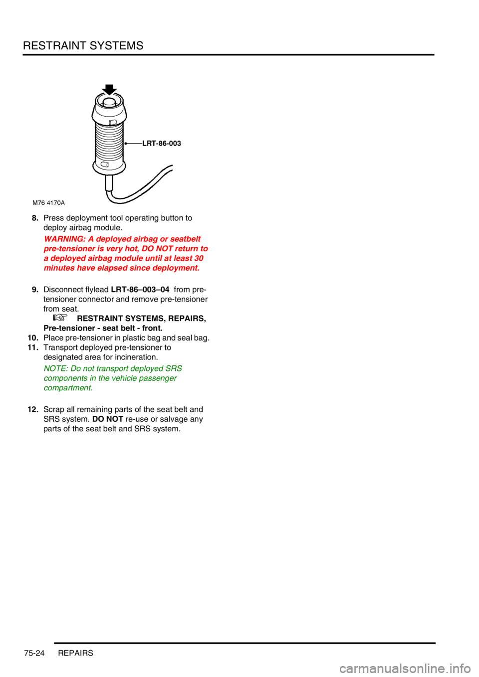
8.Press deployment tool operating button to
deploy airbag module.
WARNING: A deployed airbag or seatbelt
pre-tensioner is very hot, DO NOT return to
a deployed airbag module until at least 30
minutes have elapsed since deployment.
9.Disconnect flylead LRT-86–003–04 from pre-
tensioner connector and remove pre-tensioner
from seat.
+ RESTRAINT SYSTEMS, REPAIRS,
Pre-tensioner - seat belt - front.
10.Place pre-tensioner in plastic bag and seal bag.
11.Transport deployed pre-tensioner to
designated area for incineration.
NOTE: Do not transport deployed SRS
components in the vehicle passenger
compartment.
12.Scrap all remaining parts of the seat belt and
SRS system. DO NOT re-use or salvage any
parts of the seat belt and SRS system.
Page 606 of 1007
DOORS
ADJUSTMENTS 76-1-1
DOORS ADJUST ME NTS
Door - front or rear - adjust on striker
$% 76.28.05
Check
1.A closed door should be flush with adjacent
panels and edges have equal gaps.
Adjust
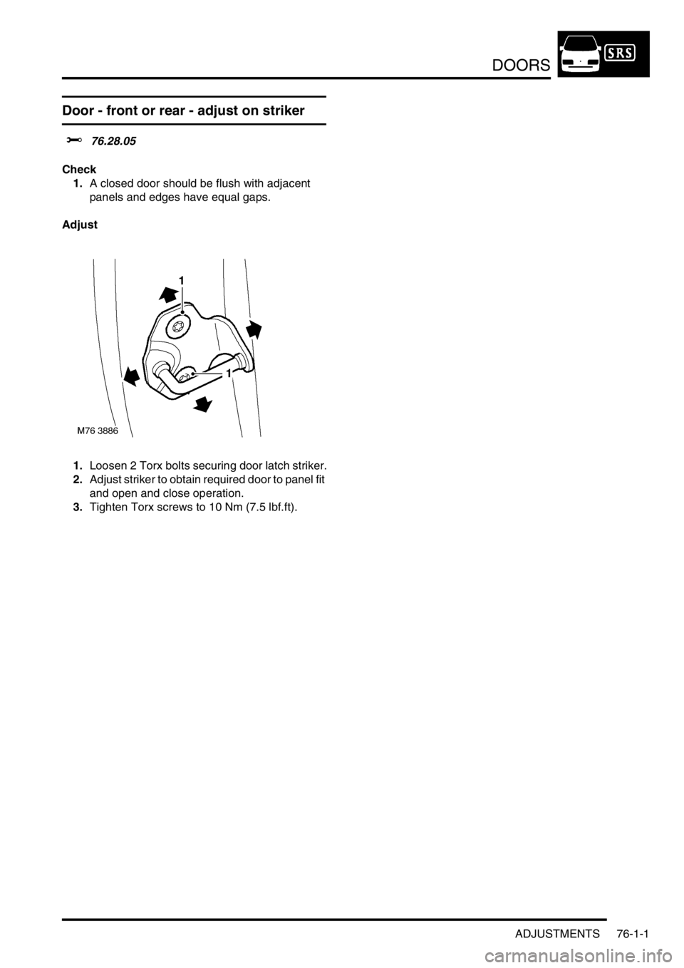
1.Loosen 2 Torx bolts securing door latch striker.
2.Adjust striker to obtain required door to panel fit
and open and close operation.
3.Tighten Torx screws to 10 Nm (7.5 lbf.ft).
Page 607 of 1007
DOORS
76-1-2 ADJUSTMENTS
Door - front - align on hinges
$% 76.28.07
Check
1.Check door for flush fit to adjacent panels and
edges for equal gaps.
Adjust
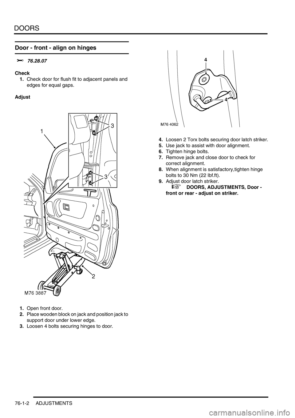
1.Open front door.
2.Place wooden block on jack and position jack to
support door under lower edge.
3.Loosen 4 bolts securing hinges to door.4.Loosen 2 Torx bolts securing door latch striker.
5.Use jack to assist with door alignment.
6.Tighten hinge bolts.
7.Remove jack and close door to check for
correct alignment.
8.When alignment is satisfactory,tighten hinge
bolts to 30 Nm (22 lbf.ft).
9.Adjust door latch striker.
+ DOORS, ADJUSTMENTS, Door -
front or rear - adjust on striker.
Page 608 of 1007
DOORS
REPAIRS 76-1-3
REPAIRS
Door assembly - front - remove for
access & refit
$% 76.28.01.99
Remove
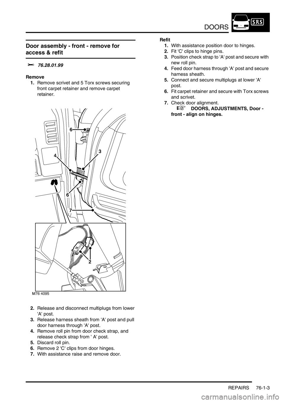
1.Remove scrivet and 5 Torx screws securing
front carpet retainer and remove carpet
retainer.
2.Release and disconnect multiplugs from lower
'A' post.
3.Release harness sheath from 'A' post and pull
door harness through 'A' post.
4.Remove roll pin from door check strap, and
release check strap from ' A' post.
5.Discard roll pin.
6.Remove 2 'C' clips from door hinges.
7.With assistance raise and remove door.Refit
1.With assistance position door to hinges.
2.Fit 'C' clips to hinge pins.
3.Position check strap to 'A' post and secure with
new roll pin.
4.Feed door harness through 'A' post and secure
harness sheath.
5.Connect and secure multiplugs at lower 'A'
post.
6.Fit carpet retainer and secure with Torx screws
and scrivet.
7.Check door alignment.
+ DOORS, ADJUSTMENTS, Door -
front - align on hinges.
Page 609 of 1007
DOORS
76-1-4 REPAIRS
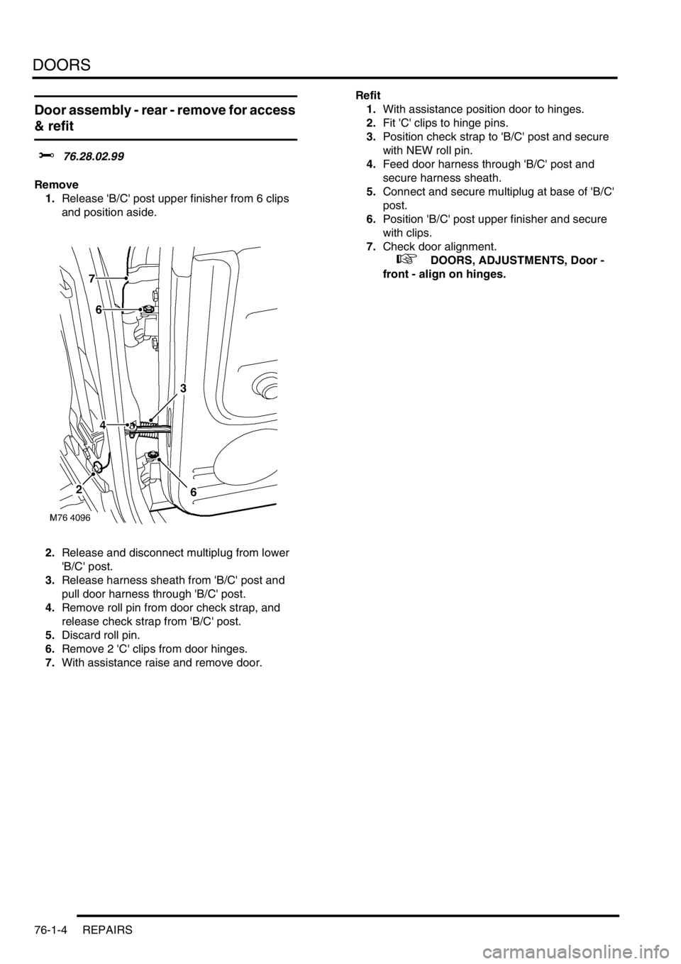
Door assembly - rear - remove for access
& refit
$% 76.28.02.99
Remove
1.Release 'B/C' post upper finisher from 6 clips
and position aside.
2.Release and disconnect multiplug from lower
'B/C' post.
3.Release harness sheath from 'B/C' post and
pull door harness through 'B/C' post.
4.Remove roll pin from door check strap, and
release check strap from 'B/C' post.
5.Discard roll pin.
6.Remove 2 'C' clips from door hinges.
7.With assistance raise and remove door.Refit
1.With assistance position door to hinges.
2.Fit 'C' clips to hinge pins.
3.Position check strap to 'B/C' post and secure
with NEW roll pin.
4.Feed door harness through 'B/C' post and
secure harness sheath.
5.Connect and secure multiplug at base of 'B/C'
post.
6.Position 'B/C' post upper finisher and secure
with clips.
7.Check door alignment.
+ DOORS, ADJUSTMENTS, Door -
front - align on hinges.
Page 610 of 1007
DOORS
REPAIRS 76-1-5
Door - tail assembly - remove for access
& refit
$% 76.28.19.99
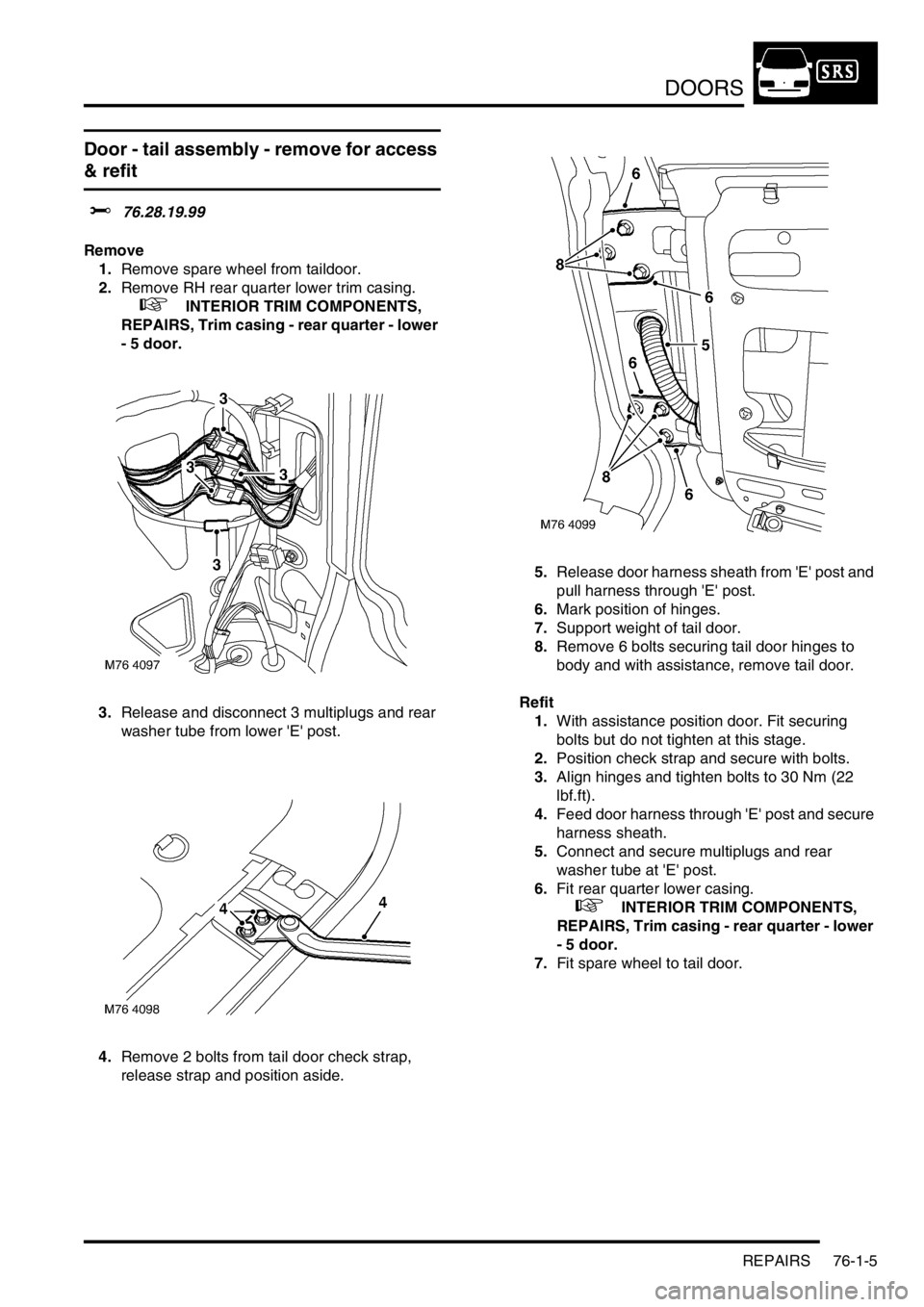
Remove
1.Remove spare wheel from taildoor.
2.Remove RH rear quarter lower trim casing.
+ INTERIOR TRIM COMPONENTS,
REPAIRS, Trim casing - rear quarter - lower
- 5 door.
3.Release and disconnect 3 multiplugs and rear
washer tube from lower 'E' post.
4.Remove 2 bolts from tail door check strap,
release strap and position aside.5.Release door harness sheath from 'E' post and
pull harness through 'E' post.
6.Mark position of hinges.
7.Support weight of tail door.
8.Remove 6 bolts securing tail door hinges to
body and with assistance, remove tail door.
Refit
1.With assistance position door. Fit securing
bolts but do not tighten at this stage.
2.Position check strap and secure with bolts.
3.Align hinges and tighten bolts to 30 Nm (22
lbf.ft).
4.Feed door harness through 'E' post and secure
harness sheath.
5.Connect and secure multiplugs and rear
washer tube at 'E' post.
6.Fit rear quarter lower casing.
+ INTERIOR TRIM COMPONENTS,
REPAIRS, Trim casing - rear quarter - lower
- 5 door.
7.Fit spare wheel to tail door.