LAND ROVER FREELANDER 2001 Workshop Manual
Manufacturer: LAND ROVER, Model Year: 2001, Model line: FREELANDER, Model: LAND ROVER FREELANDER 2001Pages: 1007, PDF Size: 23.47 MB
Page 571 of 1007
BRAKES
70-22 REPAIRS
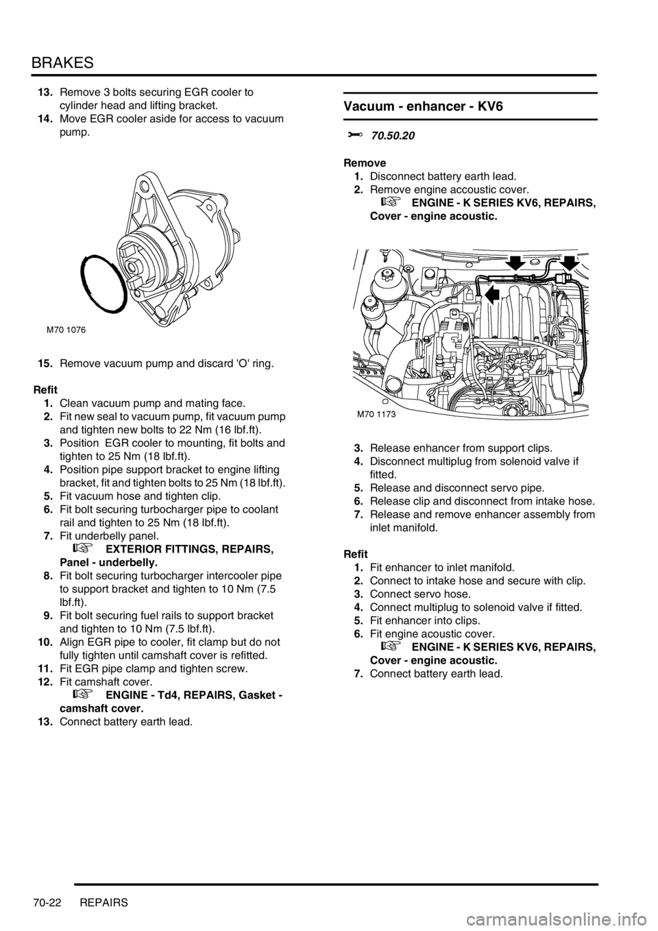
13.Remove 3 bolts securing EGR cooler to
cylinder head and lifting bracket.
14.Move EGR cooler aside for access to vacuum
pump.
15.Remove vacuum pump and discard 'O' ring.
Refit
1.Clean vacuum pump and mating face.
2.Fit new seal to vacuum pump, fit vacuum pump
and tighten new bolts to 22 Nm (16 lbf.ft).
3.Position EGR cooler to mounting, fit bolts and
tighten to 25 Nm (18 lbf.ft).
4.Position pipe support bracket to engine lifting
bracket, fit and tighten bolts to 25 Nm (18 lbf.ft).
5.Fit vacuum hose and tighten clip.
6.Fit bolt securing turbocharger pipe to coolant
rail and tighten to 25 Nm (18 lbf.ft).
7.Fit underbelly panel.
+ EXTERIOR FITTINGS, REPAIRS,
Panel - underbelly.
8.Fit bolt securing turbocharger intercooler pipe
to support bracket and tighten to 10 Nm (7.5
lbf.ft).
9.Fit bolt securing fuel rails to support bracket
and tighten to 10 Nm (7.5 lbf.ft).
10.Align EGR pipe to cooler, fit clamp but do not
fully tighten until camshaft cover is refitted.
11.Fit EGR pipe clamp and tighten screw.
12.Fit camshaft cover.
+ ENGINE - Td4, REPAIRS, Gasket -
camshaft cover.
13.Connect battery earth lead.
Vacuum - enhancer - KV6
$% 70.50.20
Remove
1.Disconnect battery earth lead.
2.Remove engine accoustic cover.
+ ENGINE - K SERIES KV6, REPAIRS,
Cover - engine acoustic.
3.Release enhancer from support clips.
4.Disconnect multiplug from solenoid valve if
fitted.
5.Release and disconnect servo pipe.
6.Release clip and disconnect from intake hose.
7.Release and remove enhancer assembly from
inlet manifold.
Refit
1.Fit enhancer to inlet manifold.
2.Connect to intake hose and secure with clip.
3.Connect servo hose.
4.Connect multiplug to solenoid valve if fitted.
5.Fit enhancer into clips.
6.Fit engine acoustic cover.
+ ENGINE - K SERIES KV6, REPAIRS,
Cover - engine acoustic.
7.Connect battery earth lead.
Page 572 of 1007
BRAKES
REPAIRS 70-23
Carrier assembly - calliper - front
$% 70.55.28
Remove
1.Raise front of vehicle.
WARNING: Do not work on or under a
vehicle supported only by a jack. Always
support the vehicle on safety stands.
2.Remove road wheel.
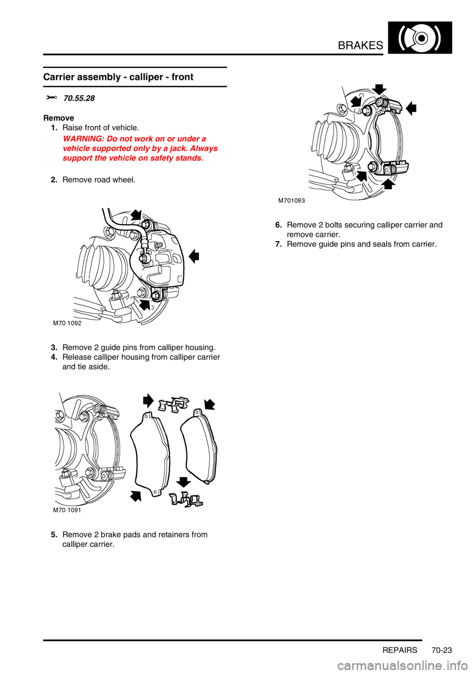
3.Remove 2 guide pins from calliper housing.
4.Release calliper housing from calliper carrier
and tie aside.
5.Remove 2 brake pads and retainers from
calliper carrier.6.Remove 2 bolts securing calliper carrier and
remove carrier.
7.Remove guide pins and seals from carrier.
Page 573 of 1007
BRAKES
70-24 REPAIRS
Refit
1.Clean guide pins and carrier mating faces.
2.Fit guide pins and seals to carrier.
3.Fit carrier, fit bolts and tighten to 100 Nm (74
lbf.ft).
4.Rotate disc by hand and scrape all scale and
rust from around edge of disc. Clean location
surfaces on calliper bracket.
5.Clean dust from brake parts using brake
cleaning fluid.
WARNING: Do not use an air line to blow
dust from brake assembly. Do not use
petroleum based fluid as damage will occur
to rubber components.
6.Clean mating faces of calliper and hub.
7.Fit pad retainers to calliper bracket.
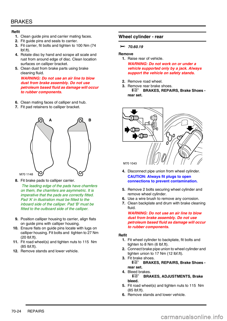
8.Fit brake pads to calliper carrier.
The leading edge of the pads have chamfers
on them, the chamfers are asymmetric. It is
imperative that the pads are correctly fitted.
Pad 'A' in illustration must be fitted to the
inboard side of the calliper. Pad 'B' must be
fitted to the outboard side of the calliper.
9.Position calliper housing to carrier, align flats
on guide pins with calliper housing.
10.Ensure flats on guide pins locate with lugs on
calliper housing. Fit bolts and tighten to 27 Nm
(20 lbf.ft).
11.Fit road wheel(s) and tighten nuts to 115 Nm
(85 lbf.ft).
12.Remove stands and lower vehicle.
Wheel cylinder - rear
$% 70.60.19
Remove
1.Raise rear of vehicle.
WARNING: Do not work on or under a
vehicle supported only by a jack. Always
support the vehicle on safety stands.
2.Remove road wheel.
3.Remove rear brake shoes.
+ BRAKES, REPAIRS, Brake Shoes -
rear set.
4.Disconnect pipe union from wheel cylinder.
CAUTION: Always fit plugs to open
connections to prevent contamination.
5.Remove 2 bolts securing wheel cylinder and
remove wheel cylinder.
6.Use a wire brush to remove any corrosion.
7.Clean backplate and drum with brake cleaning
fluid.
WARNING: Do not use an air line to blow
dust from brake assembly. Do not use
petroleum based fluid as damage will occur
to rubber components.
Refit
1.Fit wheel cylinder to backplate, fit bolts and
tighten to 8 Nm (6 lbf.ft).
2.Connect brake pipe union to wheel cylinder and
tighten union to 17 Nm (12 lbf.ft).
3.Fit brake shoes.
+ BRAKES, REPAIRS, Brake Shoes -
rear set.
4.Bleed brakes.
+ BRAKES, ADJUSTMENTS, Brake
bleed.
5.Fit road wheel(s) and tighten nuts to 115 Nm
(85 lbf.ft).
6.Remove stands and lower vehicle.
M70 1148
AB
Page 574 of 1007

BRAKES
REPAIRS 70-25
Switch - low fluid level
$% 70.65.06
Remove
1.Disconnect brake fluid level multiplug.
2.Release retaining pin and remove fluid level
switch.
Refit
1.Clean brake fluid level switch.
2.Fit brake fluid level switch.
3.Connect multiplug to brake fluid level switch.
Sensor & harness - front wheel - RH
$% 70.65.29
Remove
1.Raise front of vehicle.
WARNING: Do not work on or under a
vehicle supported only by a jack. Always
support the vehicle on safety stands.
2.Remove road wheel.
3.Remove front wheel arch liner.
+ EXTERIOR FITTINGS, REPAIRS,
Liner - front wheel arch.
4.Locate ABS sensor harness on inner wing.
5.Release ABS sensor multiplug from body clip
and disconnect multiplug.
6.Release grommet from wing valance and pull
harness through.
Page 575 of 1007

BRAKES
70-26 REPAIRS
7.Release 2 grommets from wing valance and
damper brackets
8.Release harness from brake hose clips.
9.Remove bolt securing ABS sensor to hub, if
fitted.
10.Release ABS sensor from hub.
11.Remove ABS sensor and harness.
12.Remove bush from front hub.Refit
1.Clean ABS sensors and mating faces.
2.Fit new bush to front hub.
3.Apply anti-seize grease to sensor.
4.Fit sensor to hub, ensure sensor is fully seated
in hub.
CAUTION: Ensure ABS sensor is fully
located into hub, so that sensor touches
pole wheel teeth.
5.Fit and tighten bolt securing ABS sensor to hub,
if fitted.
6.Secure harness grommets to brackets.
7.Pass sensor harness through wing valance and
secure grommet.
8.Ensure 'O' ring is in place and connect sensor
multiplug to body harness.
9.Secure multiplug in body clip.
10.Secure harness to brake hose clip.
11.Fit front wheel arch liner.
+ EXTERIOR FITTINGS, REPAIRS,
Liner - front wheel arch.
12.Fit road wheel(s) and tighten nuts to 115 Nm
(85 lbf.ft).
13.Remove stand and lower vehicle.
14.To ensure correct operation, the ABS system
MUST be tested using TestBook/T4.
Page 576 of 1007

BRAKES
REPAIRS 70-27
Sensor & harness - front wheel - LH
$% 70.65.30
Remove
1.Remove battery carrier.
+ CHARGING AND STARTING,
REPAIRS, Carrier - battery.
2.Raise front of vehicle.
WARNING: Do not work on or under a
vehicle supported only by a jack. Always
support the vehicle on safety stands.
3.Remove road wheel.
4.Remove front wheel arch liner.
+ EXTERIOR FITTINGS, REPAIRS,
Liner - front wheel arch.
5.Locate ABS sensor harness on inner wing.
6.Release ABS sensor multiplug from body clip
and disconnect multiplug.
7.Release grommet from wing valance and pull
harness through.8.Release 2 grommets from wing valance and
damper brackets
9.Release harness from brake hose clips.
10.Remove bolt securing ABS sensor to hub, if
fitted.
11.Release ABS sensor from hub.
12.Remove ABS sensor and harness.
13.Remove bush from front hub.
Page 577 of 1007

BRAKES
70-28 REPAIRS
Refit
1.Clean ABS sensors and mating faces.
2.Fit new bush to front hub.
3.Apply anti-seize grease to sensor.
4.Fit sensor to hub, ensure sensor is fully seated
in hub.
CAUTION: Ensure ABS sensor is fully
located into hub, so that sensor touches
pole wheel teeth.
5.Fit bolt securing ABS sensor to hub, if fitted.
6.Secure harness grommets to brackets.
7.Pass sensor harness through wing valance and
secure grommet.
8.Ensure 'O' ring is in place and connect sensor
multiplug to body harness.
9.Secure multiplug in body clip.
10.Secure harness to brake hose clip.
11.Fit front wheel arch liner.
+ EXTERIOR FITTINGS, REPAIRS,
Liner - front wheel arch.
12.Fit battery carrier.
+ CHARGING AND STARTING,
REPAIRS, Carrier - battery.
13.Fit road wheel(s) and tighten nuts to 115 Nm
(85 lbf.ft).
14.Remove stand and lower vehicle.
15.To ensure correct operation, the ABS system
MUST be tested using TestBook/T4.
Page 578 of 1007

BRAKES
REPAIRS 70-29
Sensor & harness - rear wheel
$% 70.65.31
Remove
1.Raise rear of vehicle.
WARNING: Do not work on or under a
vehicle supported only by a jack. Always
support the vehicle on safety stands.
2.Remove road wheel.
3.Release ABS sensor multiplug from body clip
and disconnect multiplug.
4.Release ABS sensor harness from 3 grommets
on suspension and body brackets.
5.Release harness from clip on rear brake hose.6.Remove bolt securing ABS sensor to hub, if
fitted.
7.Release sensor from rear hub and remove
sensor and harness.
8.Remove bush from rear hub.
Refit
1.Clean sensor and rear hub mating faces.
2.Fit new bush to rear hub.
3.Apply anti-seize grease to sensor.
4.Fit sensor to hub, ensure sensor is fully seated
in hub.
CAUTION: Ensure ABS sensor is fully
located into hub, so that sensor touches
pole wheel teeth.
5.Fit bolt securing ABS sensor to hub, if fitted.
6.Ensure 'O' ring is in place and connect sensor
multiplug to body harness.
7.Secure multiplug in body clip.
8.Secure harness grommets to brackets.
9.Secure harness to brake hose clip.
10.Fit road wheel(s) and tighten nuts to 115 Nm
(85 lbf.ft).
11.Remove stands and lower vehicle.
12.To ensure correct operation, the ABS system
MUST be tested using TestBook/T4.
Page 579 of 1007
BRAKES
70-30 REPAIRS
Modulator unit
$% 70.65.49
Remove
1. Td4 and KV6 models: Remove engine
accoustic cover if fitted.
+ ENGINE - Td4, REPAIRS, Cover -
engine acoustic - Up to 02.5 Model Year.
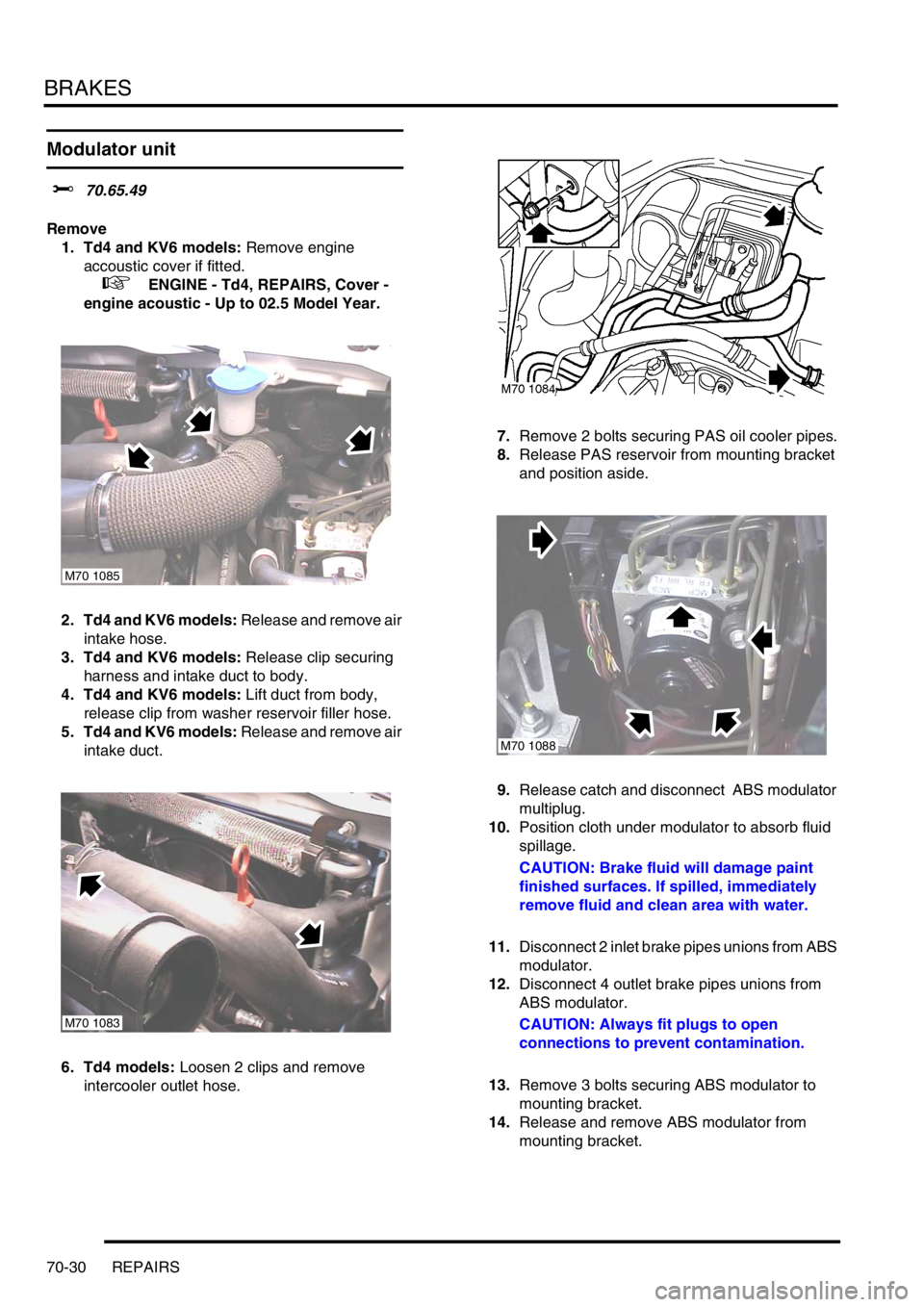
2. Td4 and KV6 models: Release and remove air
intake hose.
3. Td4 and KV6 models: Release clip securing
harness and intake duct to body.
4. Td4 and KV6 models: Lift duct from body,
release clip from washer reservoir filler hose.
5. Td4 and KV6 models: Release and remove air
intake duct.
6. Td4 models: Loosen 2 clips and remove
intercooler outlet hose.7.Remove 2 bolts securing PAS oil cooler pipes.
8.Release PAS reservoir from mounting bracket
and position aside.
9.Release catch and disconnect ABS modulator
multiplug.
10.Position cloth under modulator to absorb fluid
spillage.
CAUTION: Brake fluid will damage paint
finished surfaces. If spilled, immediately
remove fluid and clean area with water.
11.Disconnect 2 inlet brake pipes unions from ABS
modulator.
12.Disconnect 4 outlet brake pipes unions from
ABS modulator.
CAUTION: Always fit plugs to open
connections to prevent contamination.
13.Remove 3 bolts securing ABS modulator to
mounting bracket.
14.Release and remove ABS modulator from
mounting bracket.
M70 1085
M70 1083
M70 1088
Page 580 of 1007
BRAKES
REPAIRS 70-31
Refit
1.Position modulator to mounting bracket fit bolts
and tighten to 9 Nm (7 lbf.ft).
2.Clean brake pipe unions.
3.Connect brake pipe unions to modulator
ensuring pipes are connected to their correct
ports.
4.Tighten unions to 17 Nm (12 lbf.ft).
5.Connect ABS modulator multiplug and secure
catch.
6. Td4 and KV6 models: Position air intake duct
to body.
7. Td4 and KV6 models: Secure intake duct to
washer bottle filler neck and harness clip.
8. Td4 and KV6 models: Fit air intake hose.
9.Fit PAS reservoir to mounting bracket.
10.Fit bolts securing PAS oil cooler pipes and
tighten to 10 Nm (7.5 lbf.ft).
11. Td4 models: Fit intercooler outlet hose and
tighten clips.
12. Td4 and KV6 models: Fit engine accoustic
cover if fitted.
+ ENGINE - Td4, REPAIRS, Cover -
engine acoustic - Up to 02.5 Model Year.
13.Bleed brakes.
+ BRAKES, ADJUSTMENTS, Brake
bleed.
14.To ensure correct operation, the ABS system
MUST be tested using TestBook/T4.
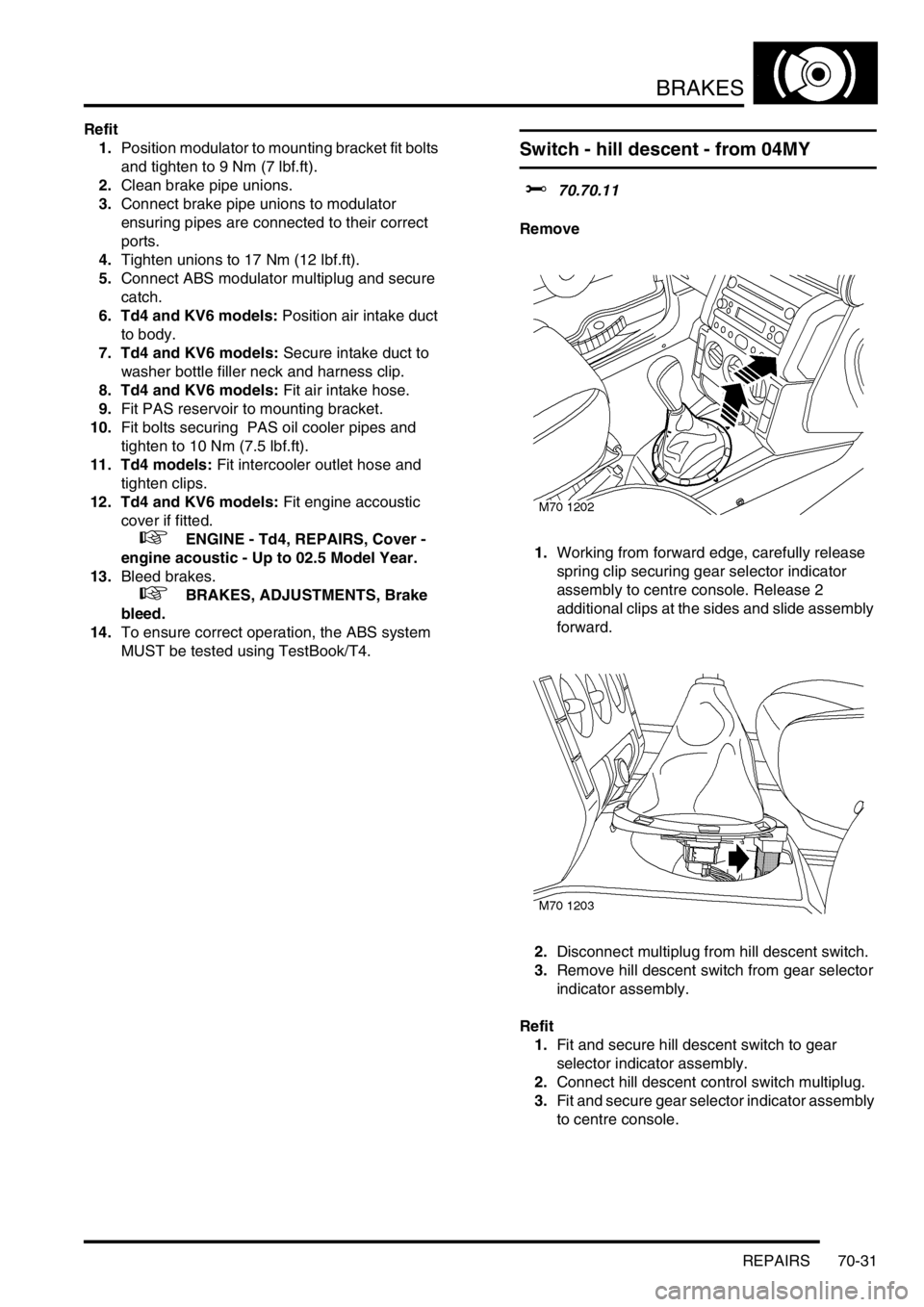
Switch - hill descent - from 04MY
$% 70.70.11
Remove
1.Working from forward edge, carefully release
spring clip securing gear selector indicator
assembly to centre console. Release 2
additional clips at the sides and slide assembly
forward.
2.Disconnect multiplug from hill descent switch.
3.Remove hill descent switch from gear selector
indicator assembly.
Refit
1.Fit and secure hill descent switch to gear
selector indicator assembly.
2.Connect hill descent control switch multiplug.
3.Fit and secure gear selector indicator assembly
to centre console.