LAND ROVER FREELANDER 2001 Workshop Manual
Manufacturer: LAND ROVER, Model Year: 2001, Model line: FREELANDER, Model: LAND ROVER FREELANDER 2001Pages: 1007, PDF Size: 23.47 MB
Page 581 of 1007
BRAKES
70-32 REPAIRS
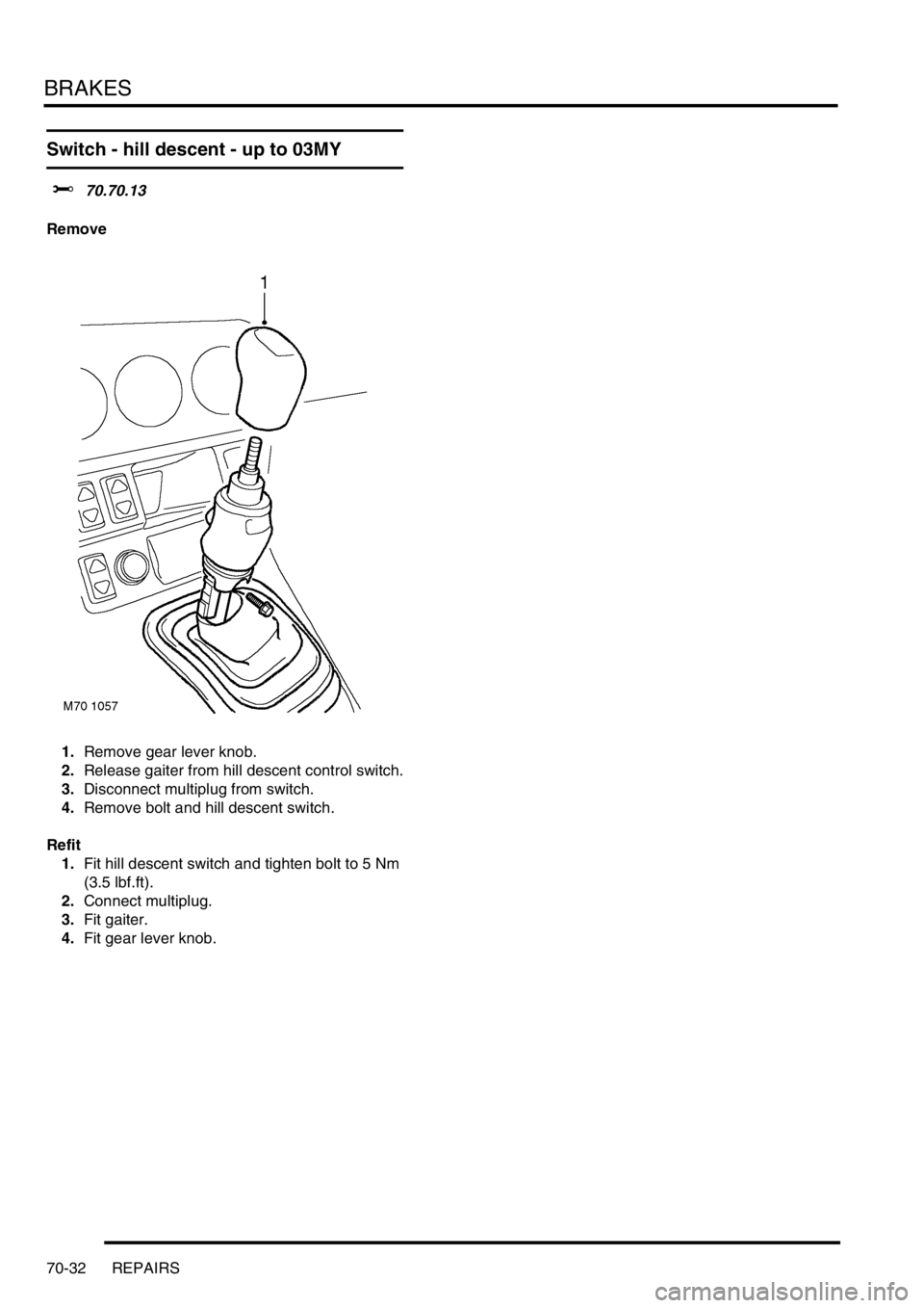
Switch - hill descent - up to 03MY
$% 70.70.13
Remove
1.Remove gear lever knob.
2.Release gaiter from hill descent control switch.
3.Disconnect multiplug from switch.
4.Remove bolt and hill descent switch.
Refit
1.Fit hill descent switch and tighten bolt to 5 Nm
(3.5 lbf.ft).
2.Connect multiplug.
3.Fit gaiter.
4.Fit gear lever knob.
Page 582 of 1007
RESTRAINT SYSTEMS
REPAIRS 75-1
RESTRAINT SYSTEMS REPAIRS
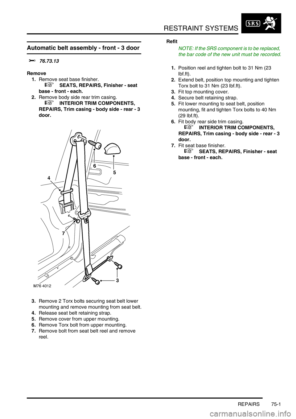
Automatic belt assembly - front - 3 door
$% 76.73.13
Remove
1.Remove seat base finisher.
+ SEATS, REPAIRS, Finisher - seat
base - front - each.
2.Remove body side rear trim casing.
+ INTERIOR TRIM COMPONENTS,
REPAIRS, Trim casing - body side - rear - 3
door.
3.Remove 2 Torx bolts securing seat belt lower
mounting and remove mounting from seat belt.
4.Release seat belt retaining strap.
5.Remove cover from upper mounting.
6.Remove Torx bolt from upper mounting.
7.Remove bolt from seat belt reel and remove
reel.Refit
NOTE: If the SRS component is to be replaced,
the bar code of the new unit must be recorded.
1.Position reel and tighten bolt to 31 Nm (23
lbf.ft).
2.Extend belt, position top mounting and tighten
Torx bolt to 31 Nm (23 lbf.ft).
3.Fit top mounting cover.
4.Secure belt retaining strap.
5.Fit lower mounting to seat belt, position
mounting, fit and tighten Torx bolts to 40 Nm
(29 lbf.ft).
6.Fit body rear side trim casing.
+ INTERIOR TRIM COMPONENTS,
REPAIRS, Trim casing - body side - rear - 3
door.
7.Fit seat base finisher.
+ SEATS, REPAIRS, Finisher - seat
base - front - each.
Page 583 of 1007
RESTRAINT SYSTEMS
75-2 REPAIRS
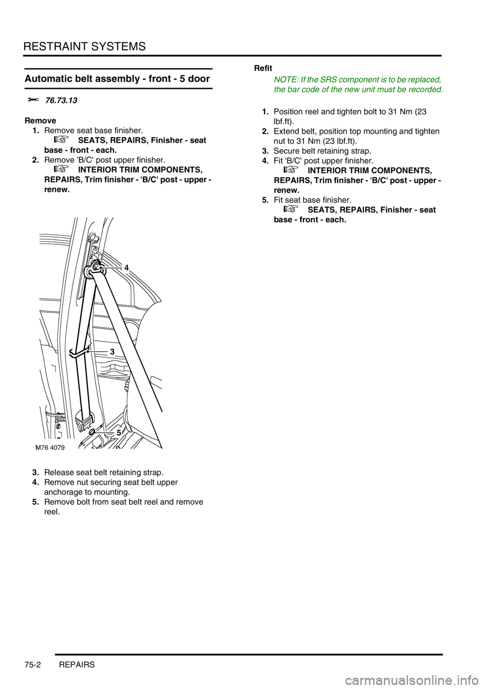
Automatic belt assembly - front - 5 door
$% 76.73.13
Remove
1.Remove seat base finisher.
+ SEATS, REPAIRS, Finisher - seat
base - front - each.
2.Remove 'B/C' post upper finisher.
+ INTERIOR TRIM COMPONENTS,
REPAIRS, Trim finisher - 'B/C' post - upper -
renew.
3.Release seat belt retaining strap.
4.Remove nut securing seat belt upper
anchorage to mounting.
5.Remove bolt from seat belt reel and remove
reel.Refit
NOTE: If the SRS component is to be replaced,
the bar code of the new unit must be recorded.
1.Position reel and tighten bolt to 31 Nm (23
lbf.ft).
2.Extend belt, position top mounting and tighten
nut to 31 Nm (23 lbf.ft).
3.Secure belt retaining strap.
4.Fit 'B/C' post upper finisher.
+ INTERIOR TRIM COMPONENTS,
REPAIRS, Trim finisher - 'B/C' post - upper -
renew.
5.Fit seat base finisher.
+ SEATS, REPAIRS, Finisher - seat
base - front - each.
Page 584 of 1007
RESTRAINT SYSTEMS
REPAIRS 75-3
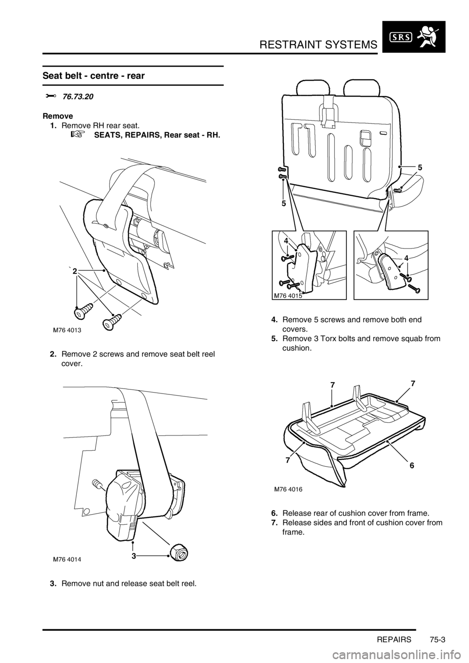
Seat belt - centre - rear
$% 76.73.20
Remove
1.Remove RH rear seat.
+ SEATS, REPAIRS, Rear seat - RH.
2.Remove 2 screws and remove seat belt reel
cover.
3.Remove nut and release seat belt reel.4.Remove 5 screws and remove both end
covers.
5.Remove 3 Torx bolts and remove squab from
cushion.
6.Release rear of cushion cover from frame.
7.Release sides and front of cushion cover from
frame.
Page 585 of 1007
RESTRAINT SYSTEMS
75-4 REPAIRS
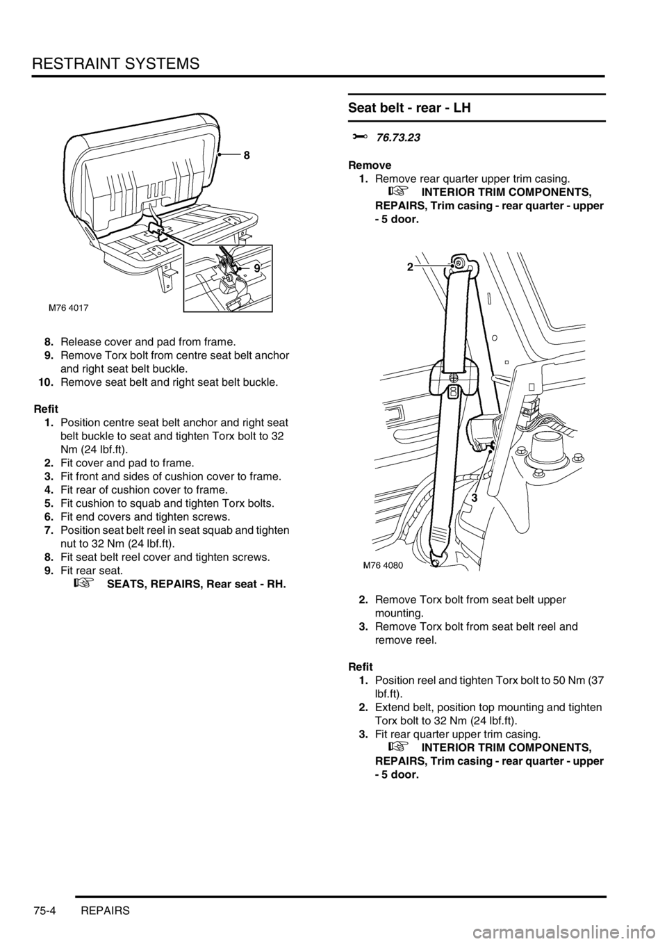
8.Release cover and pad from frame.
9.Remove Torx bolt from centre seat belt anchor
and right seat belt buckle.
10.Remove seat belt and right seat belt buckle.
Refit
1.Position centre seat belt anchor and right seat
belt buckle to seat and tighten Torx bolt to 32
Nm (24 lbf.ft).
2.Fit cover and pad to frame.
3.Fit front and sides of cushion cover to frame.
4.Fit rear of cushion cover to frame.
5.Fit cushion to squab and tighten Torx bolts.
6.Fit end covers and tighten screws.
7.Position seat belt reel in seat squab and tighten
nut to 32 Nm (24 lbf.ft).
8.Fit seat belt reel cover and tighten screws.
9.Fit rear seat.
+ SEATS, REPAIRS, Rear seat - RH.
Seat belt - rear - LH
$% 76.73.23
Remove
1.Remove rear quarter upper trim casing.
+ INTERIOR TRIM COMPONENTS,
REPAIRS, Trim casing - rear quarter - upper
- 5 door.
2.Remove Torx bolt from seat belt upper
mounting.
3.Remove Torx bolt from seat belt reel and
remove reel.
Refit
1.Position reel and tighten Torx bolt to 50 Nm (37
lbf.ft).
2.Extend belt, position top mounting and tighten
Torx bolt to 32 Nm (24 lbf.ft).
3.Fit rear quarter upper trim casing.
+ INTERIOR TRIM COMPONENTS,
REPAIRS, Trim casing - rear quarter - upper
- 5 door.
Page 586 of 1007
RESTRAINT SYSTEMS
REPAIRS 75-5
Adjustable mounting - seat belt - 'B' pillar
$% 76.73.26
Remove
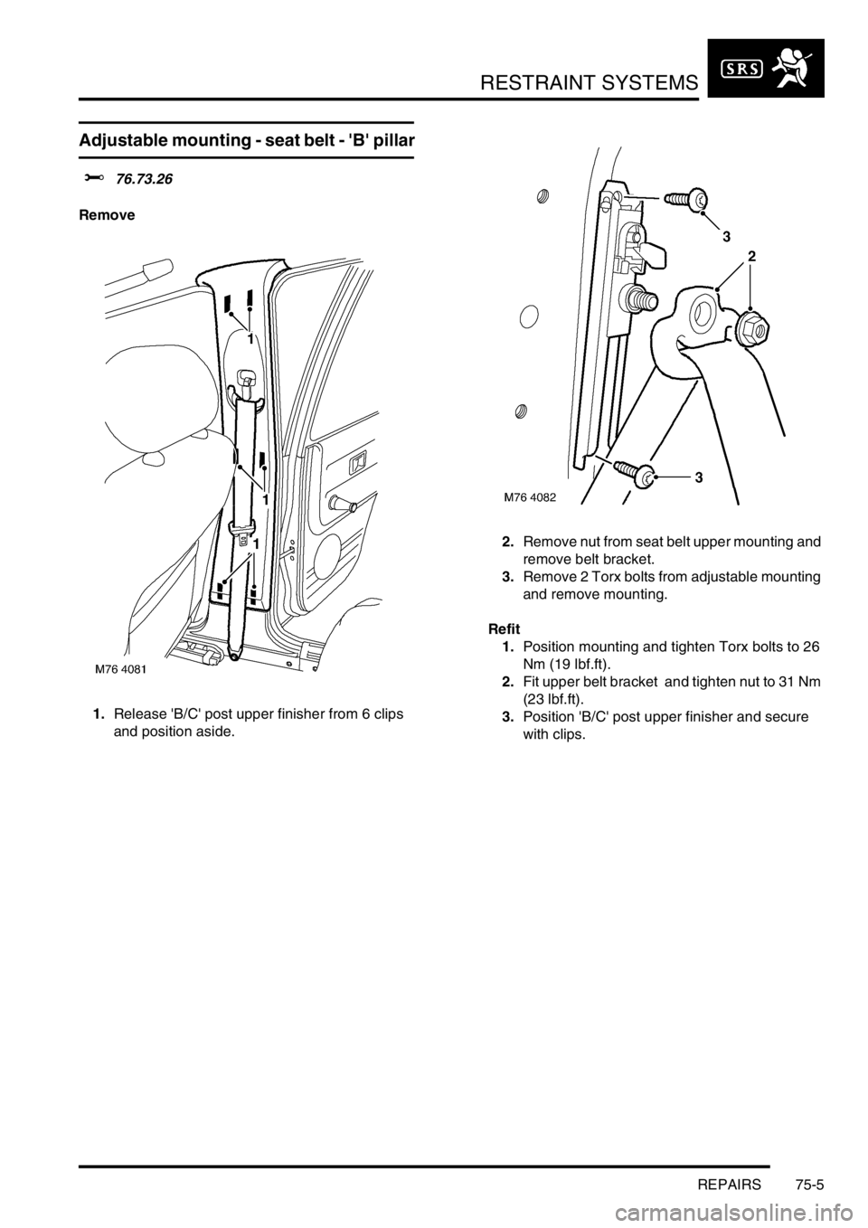
1.Release 'B/C' post upper finisher from 6 clips
and position aside.2.Remove nut from seat belt upper mounting and
remove belt bracket.
3.Remove 2 Torx bolts from adjustable mounting
and remove mounting.
Refit
1.Position mounting and tighten Torx bolts to 26
Nm (19 lbf.ft).
2.Fit upper belt bracket and tighten nut to 31 Nm
(23 lbf.ft).
3.Position 'B/C' post upper finisher and secure
with clips.
Page 587 of 1007
RESTRAINT SYSTEMS
75-6 REPAIRS
Stalk - rear seat belt - LH - 3 door
$% 76.73.32
Remove
1.Remove rear seat.
+ SEATS, REPAIRS, Cushion & squab
- rear seat - bench type - 3 door.
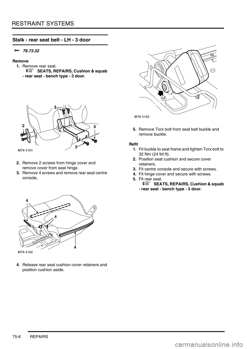
2.Remove 2 screws from hinge cover and
remove cover from seat hinge.
3.Remove 4 screws and remove rear seat centre
console.
4.Release rear seat cushion cover retainers and
position cushion aside.5.Remove Torx bolt from seat belt buckle and
remove buckle.
Refit
1.Fit buckle to seat frame and tighten Torx bolt to
32 Nm (24 lbf.ft).
2.Position seat cushion and secure cover
retainers.
3.Fit centre console and secure with screws.
4.Fit hinge cover and secure with screws.
5.Fit rear seat.
+ SEATS, REPAIRS, Cushion & squab
- rear seat - bench type - 3 door.
Page 588 of 1007
RESTRAINT SYSTEMS
REPAIRS 75-7
Stalk - rear seat belt - LH - 5 door
$% 76.73.32
Remove
1.Fold rear seat forward.
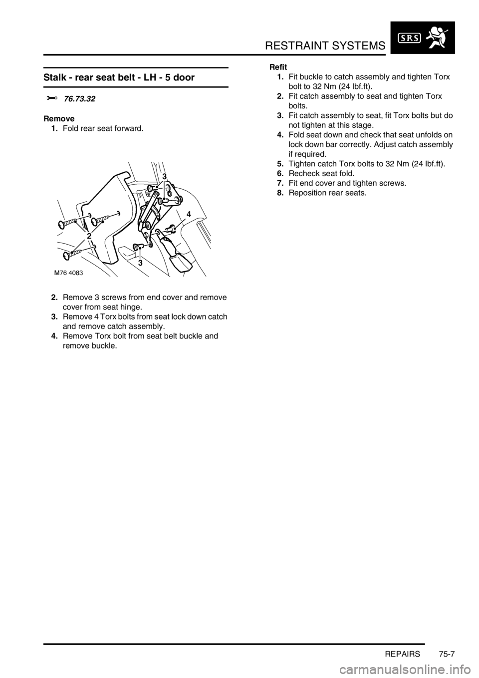
2.Remove 3 screws from end cover and remove
cover from seat hinge.
3.Remove 4 Torx bolts from seat lock down catch
and remove catch assembly.
4.Remove Torx bolt from seat belt buckle and
remove buckle.Refit
1.Fit buckle to catch assembly and tighten Torx
bolt to 32 Nm (24 lbf.ft).
2.Fit catch assembly to seat and tighten Torx
bolts.
3.Fit catch assembly to seat, fit Torx bolts but do
not tighten at this stage.
4.Fold seat down and check that seat unfolds on
lock down bar correctly. Adjust catch assembly
if required.
5.Tighten catch Torx bolts to 32 Nm (24 lbf.ft).
6.Recheck seat fold.
7.Fit end cover and tighten screws.
8.Reposition rear seats.
Page 589 of 1007
RESTRAINT SYSTEMS
75-8 REPAIRS
Pre-tensioner - seat belt - front
$% 76.73.75
Remove
WARNING: It is imperative that before any
work is undertaken on the SRS system the
appropriate information is read thoroughly.
WARNING: When removing, testing or
installing a seatbelt pre-tensioner, do not
lean directly over it or block the end of the
piston tube.
1.Make the SRS system safe.
+ GENERAL INFORMATION,
Supplementary restraint system
precautions.
2.Remove rear console.
+ INTERIOR TRIM COMPONENTS,
REPAIRS, Console - rear.
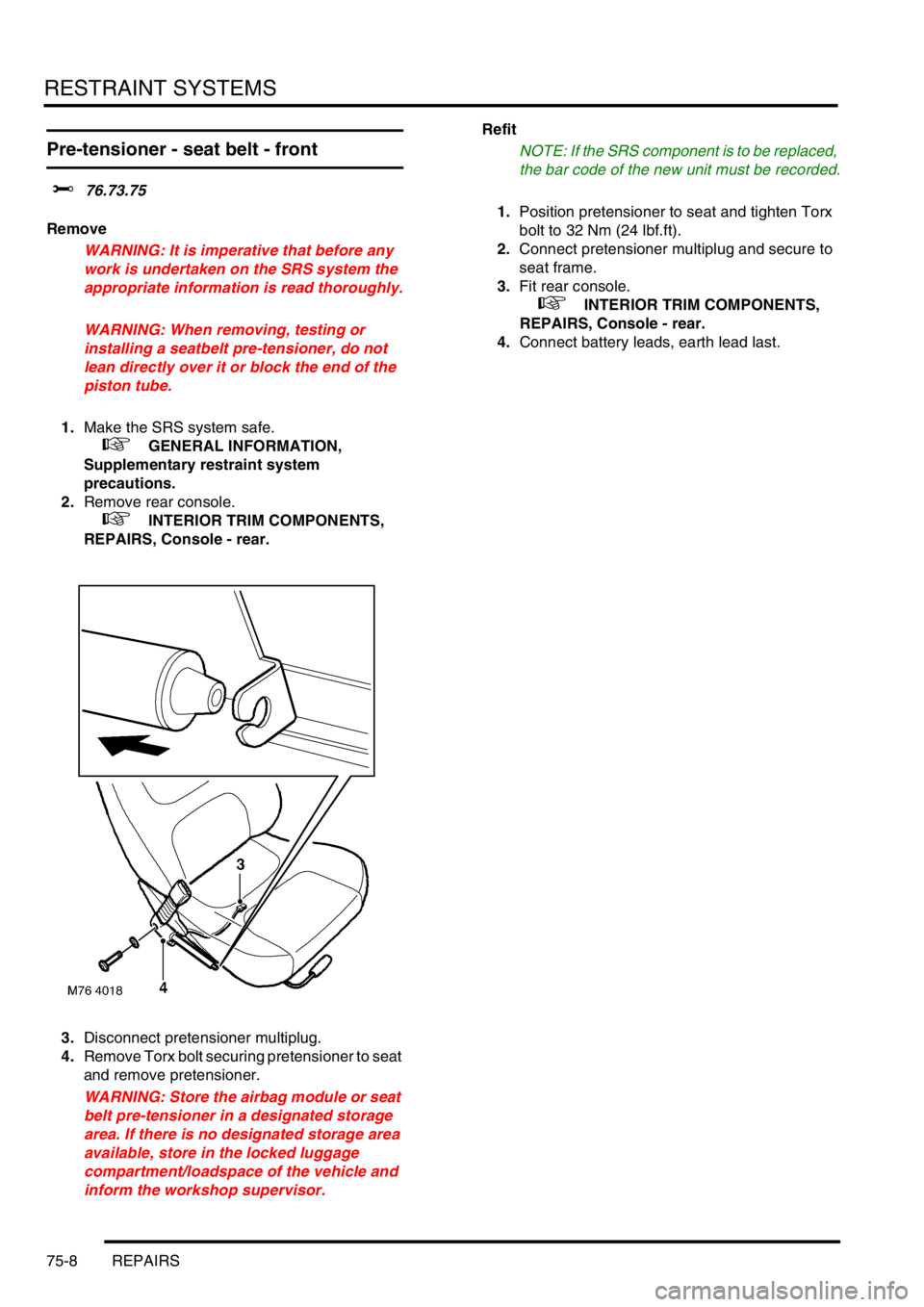
3.Disconnect pretensioner multiplug.
4.Remove Torx bolt securing pretensioner to seat
and remove pretensioner.
WARNING: Store the airbag module or seat
belt pre-tensioner in a designated storage
area. If there is no designated storage area
available, store in the locked luggage
compartment/loadspace of the vehicle and
inform the workshop supervisor.Refit
NOTE: If the SRS component is to be replaced,
the bar code of the new unit must be recorded.
1.Position pretensioner to seat and tighten Torx
bolt to 32 Nm (24 lbf.ft).
2.Connect pretensioner multiplug and secure to
seat frame.
3.Fit rear console.
+ INTERIOR TRIM COMPONENTS,
REPAIRS, Console - rear.
4.Connect battery leads, earth lead last.
Page 590 of 1007
RESTRAINT SYSTEMS
REPAIRS 75-9
Pre-tensioner - seat belt - front -
deployment - off vehicle
$% 76.73.78
These guidelines are written to aid authorised
personnel to carry out the safe disposal of airbag
modules when removed from the vehicle.
Deploy
It is imperative that before any work is
undertaken on the SRS system, the
appropriate information is read thoroughly.
1.Make the SRS system safe.
+ GENERAL INFORMATION, SRS
component manual deployment.
2.Remove seat belt pre-tensioner from vehicle.
+ RESTRAINT SYSTEMS, REPAIRS,
Pre-tensioner - seat belt - front.
3.Check condition of deployment tool LRT-86-
003 and associated fly leads.
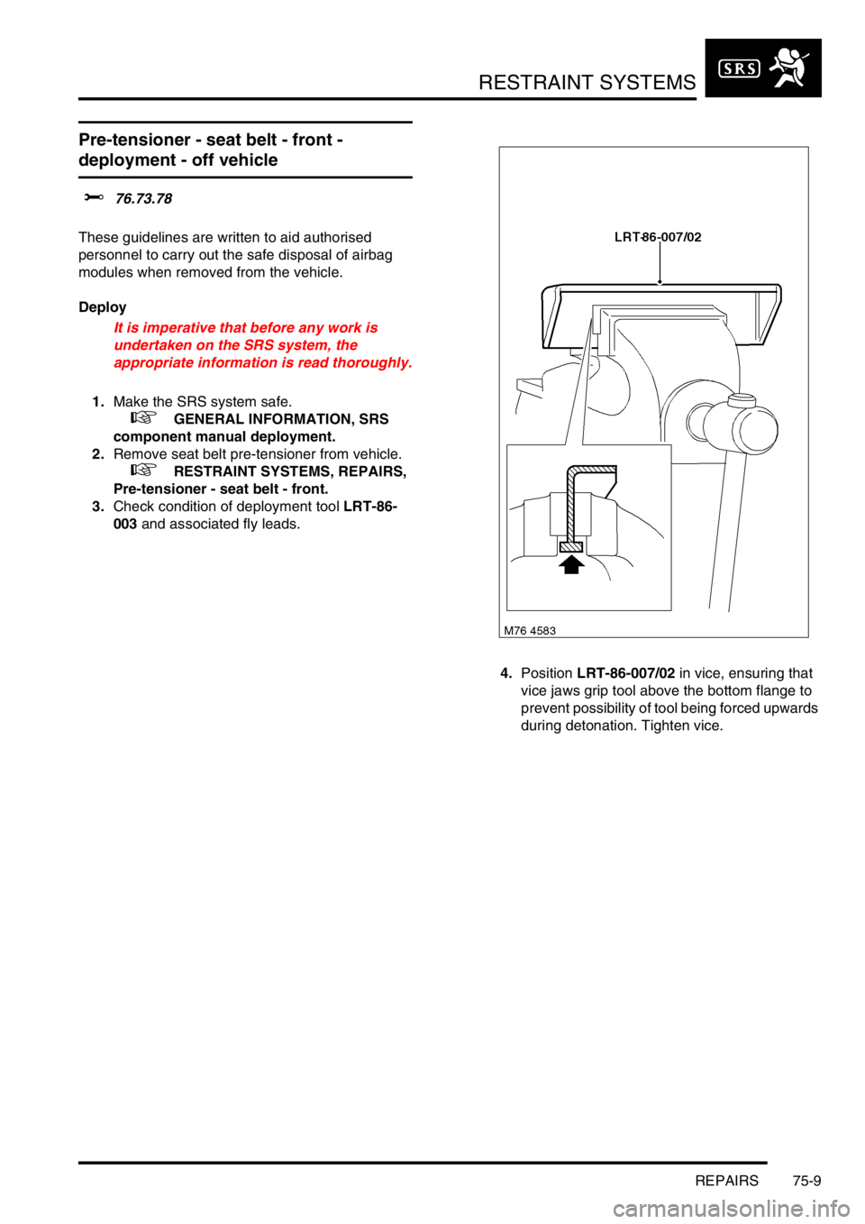
4.Position LRT-86-007/02 in vice, ensuring that
vice jaws grip tool above the bottom flange to
prevent possibility of tool being forced upwards
during detonation. Tighten vice.