LAND ROVER FRELANDER 2 2006 Repair Manual
Manufacturer: LAND ROVER, Model Year: 2006, Model line: FRELANDER 2, Model: LAND ROVER FRELANDER 2 2006Pages: 3229, PDF Size: 78.5 MB
Page 1211 of 3229
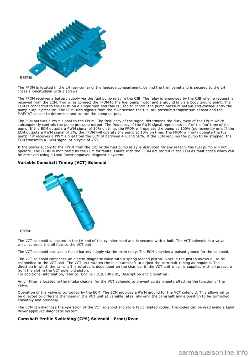
The FPDM i s located i n t he LH rear corner of the l uggage compart ment, behind t he t rim panel and is s ecured t o t he LHchas s is l ongi tudinal wi th 2 s crews.
The FPDM receives a bat tery s uppl y via t he fuel pump relay i n t he CJB. The relay is energis ed by t he CJB when a reques t isreceived from the ECM. Two wires connect t he FPDM t o t he fuel pump mot or and a ground i s via a body ground poi nt. TheECM i s connected t o t he FPDM on a si ngle wi re and this is us ed t o cont rol t he pump pres s ure out put and cons equentl y t hepump output pres s ure. The ECM us es s ignals from t he MAP s ens or, the fuel rail pres s ure/t emperat ure s ens or and t heMAF/IAT s ensor t o determine and control the pump out put.
The ECM out put s a PW M s ignal to the FPDM. The frequency of t he s ignal det ermi nes the dut y cycle of t he FPDM whi chs ubs equent ly controls t he pump press ure out put. The frequency of t he PW M s ignal repres ent s half of t he 'on' ti me of t hepump. If t he ECM out put s a PW M s ignal of 50% on t ime, the FPDM will operat e t he pump at 100% (permanentl y on). If theECM out put s a PW M s ignal of 5%, the FPDM wil l operat e t he pump at 10% on t ime. The FPDM wi ll only operat e t he fuelpump i f it receives a PW M s i gnal from the ECM of bet ween 4% and 50%. If t he ECM requi res t he pump t o be s t opped, theECM t rans mit s a PW M s i gnal at a cycl e of 75%.
If the power s uppl y to the FPDM from t he CJB or the fuel pump rel ay is di srupt ed for any reason, t he fuel pump wi ll notoperate. The FPDM i s monit ored by the ECM for faul ts . Faul ts wit h t he FPDM are st ored i n t he ECM as faul t codes whi ch canbe ret rieved usi ng a Land Rover approved diagnost ic sys tem.
Variable Camshaft Timing (VCT) Solenoid
The VCT s olenoid i s located in t he LH end of t he cyl inder head and i s s ecured wit h a bol t. The VCT s olenoid is a val vewhich controls t he oil flow t o t he VCT unit .
The VCT s olenoid recei ves a fus ed batt ery s upply vi a the main relay. The ECM provides a pul s ed ground for t he s olenoi d.
The VCT s olenoid compri s es an electro-magneti c val ve wit h a spring l oaded pi st on. Slots in t he pis t on all ows oil to bechannell ed to the VCT uni t. The VCT uni t rot at es t he inlet cams haft t o adjus t the cams haft t iming as requi red. Thedirect ion i n which t he cams haft is rot at ed i s dependent on the chamber in t he VCT unit whi ch is suppli ed wit h oil press urefrom the s lot i n t he VCT s olenoid pi st on.For addit ional informat ion, refer t o: Engi ne - 3.2L (303-01, Descripti on and Operat ion).
An oil fil ter i s located i n t he int ake channel for the VCT sol enoid to prevent contami nant s affect ing the funct ion of t hevalve.
Operat ion of t he val ve is controll ed by the ECM. The ECM provides a PW M ground for the VCT sol enoi d. This allows oi l tobe direct ed t o different chambers i n t he VCT unit at vari abl e rat es , al lowi ng the cams haft angle pos it ion t o be controll eds moothly and precis ely.
The ECM can diagnose the operat ion of t he VCT s olenoid and st ore fault related codes. The codes can be read us ing a LandRover approved diagnost ic sys tem.
Camshaft Profile Switching (CPS) Solenoid - Front/Rear
Page 1212 of 3229
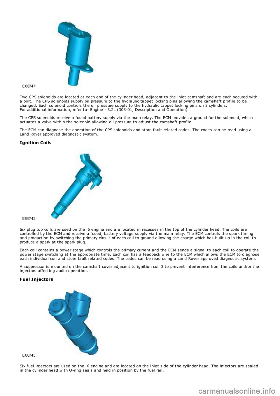
Two CPS s olenoids are located at each end of the cyli nder head, adjacent t o t he inlet cams haft and are each s ecured wi tha bolt . The CPS s olenoids s uppl y oil pres s ure t o t he hydrauli c tappet locki ng pins al lowing t he cams haft profile to bechanged. Each s olenoid controls t he oil press ure supply to the hydrauli c tappet locking pins on 3 cyl inders .For addit ional informat ion, refer t o: Engi ne - 3.2L (303-01, Descripti on and Operat ion).
The CPS s olenoids receive a fus ed batt ery s upply via the main relay. The ECM provides a ground for t he s ol enoi d, whichact uates a val ve wit hin t he s olenoid al lowing oi l pres sure t o adjus t the cams haft profil e.
The ECM can diagnose the operat ion of t he CPS s olenoids and s t ore faul t rel at ed codes . The codes can be read us ing aLand Rover approved diagnos t ic s ys tem.
Ignition Coils
Six pl ug top coi ls are used on the i6 engine and are located in reces s es in t he t op of the cyli nder head. The coi ls arecont rol led by t he ECM and recei ve a fus ed, bat t ery volt age s upply vi a t he main rel ay. The ECM controls t he s park t imingand product ion by swit ching the primary circuit of each coil to ground all owing t he charge which has buil t up in the coil t oproduce a s park at t he s park plug.
Each coi l contai ns a power st age which controls t he pri mary current and the ECM s ends a si gnal t o each coi l to operat e t hepower st age s wit chi ng at the appropriate ti me. Each coil has a feedback wi re to t he ECM whi ch all ows the ECM to diagnos eeach individual coi l and st ore fault related codes. The codes can be read us ing a Land Rover approved diagnos t ic s yst em.
A s uppres sor i s mounted on the cams haft cover adjacent to ignit ion coil 3 t o prevent int erference from t he coi ls and/or t heinject ors affecti ng audi o operat ion.
Fuel Injectors
Six fuel injectors are us ed on the i 6 engine and are located on t he i nl et s ide of t he cyl inder head. The inject ors are s eal edin the cyli nder head wi th O -ring s eals and held in pos it ion by the fuel rail .
Page 1213 of 3229
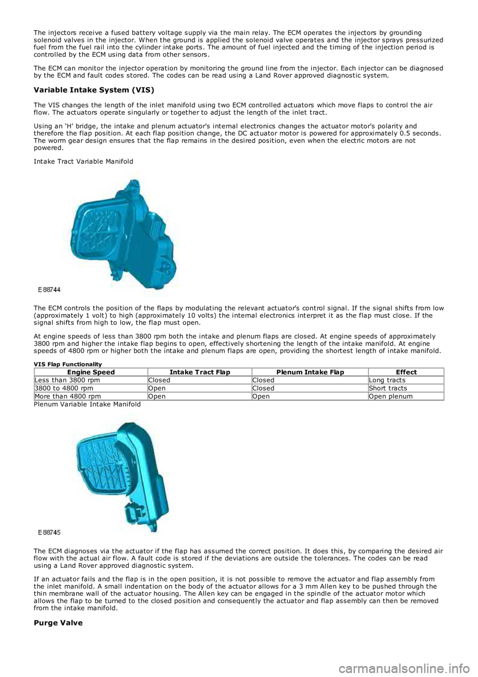
The inject ors recei ve a fus ed bat tery vol tage s upply via the main relay. The ECM operates t he i nject ors by groundi ngs olenoi d valves in the injector. W hen t he ground is appl ied t he s olenoi d valve operat es and the injector s prays pres s uri zedfuel from the fuel rail i nt o t he cyl inder int ake ports . The amount of fuel injected and the t iming of t he inject ion peri od iscont rol led by t he ECM us ing dat a from other s ens ors .
The ECM can monit or the injector operat ion by moni toring t he ground l ine from the i njector. Each i njector can be diagnosedby t he ECM and faul t codes s t ored. The codes can be read us ing a Land Rover approved diagnos t ic s ys tem.
Variable Intake System (VIS)
The VIS changes the length of t he inl et manifol d us ing t wo ECM controll ed act uators which move flaps t o cont rol t he airfl ow. The act uators operate s i ngul arly or t oget her to adjust t he l engt h of the inlet t ract.
Us ing an 'H' bridge, the intake and pl enum act uator's i nt ernal electroni cs changes the act uat or motor's polarit y andt herefore the flap pos it ion. At each fl ap pos i ti on change, the DC act uator mot or i s powered for approxi matel y 0.5 seconds .The worm gear des ign ens ures t hat the flap remains in t he desi red pos it ion, even when the el ect ri c mot ors are notpowered.
Int ake Tract Variabl e Manifol d
The ECM controls t he posi ti on of the flaps by modul at ing the relevant act uat or's cont rol s ignal. If the s ignal s hi ft s from low(approxi mately 1 volt ) to hi gh (approxi matel y 10 volt s) t he i nt ernal electroni cs interpret i t as the flap must cl os e. If thes ignal shi ft s from hi gh to low, t he fl ap mus t open.
At engi ne s peeds of l es s t han 3800 rpm both the i ntake and plenum flaps are clos ed. At engine s peeds of approxi matel y3800 rpm and higher the i ntake flap begins t o open, effecti vel y s hort eni ng the length of t he int ake manifol d. At engi nes peeds of 4800 rpm or higher bot h t he int ake and plenum flaps are open, providi ng the short es t length of i ntake manifold.
VIS Flap Functionality
Engine SpeedIntake T ract FlapPlenum Intake FlapEffectLess than 3800 rpmClos edClos edLong tract s
3800 t o 4800 rpmOpenClos edShort t racts
More than 4800 rpmOpenOpenOpen plenumPlenum Variable Int ake Mani fold
The ECM di agnos es vi a t he act uator i f the flap has as s umed the correct pos i ti on. It does this , by compari ng the des ired airfl ow wi th the act ual air flow. A fault code is st ored i f the deviat ions are outs ide t he t olerances. The codes can be readus ing a Land Rover approved di agnos ti c s ys t em.
If an act uat or fai ls and t he flap i s in the open pos it ion, it i s not pos s ible to remove t he act uator and flap as sembl y fromt he inlet mani fold. A smal l indentat ion on t he body of the actuat or al lows for a 3 mm Al len key t o be pus hed through t het hi n membrane wall of the act uat or hous ing. The All en key can be engaged i n t he spi ndl e of t he act uat or mot or whi chall ows the flap to be turned to the clos ed pos it ion and cons equent ly the actuat or and flap as s embly can t hen be removedfrom the i ntake manifold.
Purge Valve
Page 1214 of 3229
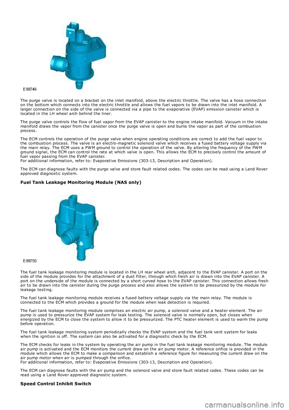
The purge valve i s located on a bracket on the i nlet manifold, above the el ect ri c throt t le. The val ve has a hos e connecti onon t he bott om whi ch connect s i nt o t he electric t hrot tl e and all ows t he fuel vapors to be drawn i nto the i nlet manifold. Alarger connect ion on t he s ide of t he valve i s connect ed via a pipe t o t he evaporati ve (EVAP) emis s ion canis ter whi ch islocated i n t he LH wheel arch behind t he li ner.
The purge valve controls t he flow of fuel vapor from t he EVAP cani st er to the engine intake mani fold. Vacuum in the intakemanifold draws the vapor from t he canis ter once the purge val ve is open and burns the vapor as part of the combus ti onprocess .
The ECM controls t he operati on of the purge val ve when engine operat ing condi ti ons are correct t o add t he fuel vapor t ot he combus ti on process . The valve i s an electro-magnet ic s olenoid valve whi ch receives a fused bat tery vol tage s upply vi at he main relay. The ECM us es a PW M ground t o cont rol t he operati on of the val ve. By al tering t he frequency of the PW Mground s ignal, t he ECM can cont rol t he rat e at whi ch val ve is open. Thi s all ows the ECM to precis ely control t he amount offuel vapor pas si ng from the EVAP canis ter.For addit ional informat ion, refer t o: Evaporat ive Emi s si ons (303-13, Des cript ion and Operat ion).
The ECM can diagnose fault s wi th the purge val ve and s tore fault relat ed codes . The codes can be read us i ng a Land Roverapproved diagnos t ic s yst em.
Fuel Tank Leakage Monitoring Module (NAS only)
The fuel t ank leakage moni toring module is l ocat ed in the LH rear wheel arch, adjacent to t he EVAP canis ter. A port on t hes ide of t he module provi des for t he att achment of a dus t fi lt er, t hrough which fres h air i s drawn i nto the EVAP canis ter. Aport on t he unders ide of t he module i s connected by a s hort curved hos e to t he EVAP canis ter. Thi s connecti on allows fres hair t o be drawn int o t he cani st er during t he purge proces s and als o al lows t he s yst em to be pres surized by t he module forleakage tes t ing.
The fuel t ank leakage moni toring module receives a fus ed bat tery vol tage s upply via the main relay. The modul e i sconnected t o t he ECM whi ch provides a ground for the modul e when l eak det ect ion i s required.
The fuel t ank leakage moni toring module compris es an elect ric ai r pump, a s olenoi d valve and a heat er el ement. The airpump i s used to press urize t he EVAP s ys t em for leak tes t ing. The sol enoi d valve is normall y open, but clos es whenenergized by t he ECM t o clos e t he s ys t em t o al low i t to be pres s urized. The PTC heater element is us ed t o warm t he pumpbefore operati on.
The fuel t ank leakage moni toring s yst em periodicall y checks the EVAP sys tem and t he fuel tank vent s ys t em for leakswhen t he ignit ion i s off. The s ys t em can als o be act ivated for a diagnos ti c check by t he ECM.
The ECM checks for leaks in t he s yst em by operati ng the ai r pump in the fuel tank leakage monit ori ng modul e. The modul eair pump i s acti vat ed and t he ECM monit ors the current draw on t he air pump motor. A reference ori fi ce is provi ded in t hemodule whi ch allows the ECM to make a comparis on and es t abl is h a reference figure for meas uring the current draw on theair pump motor when air i s pumped through the orifice.For addit ional informat ion, refer t o: Evaporat ive Emi s si ons (303-13, Des cript ion and Operat ion).
The ECM can diagnose fault s wi th the ai r pump and the sol enoi d val ve and s tore faul t relat ed codes . Thes e codes can beread us ing a Land Rover approved diagnos t ic s ys tem.
Speed Control Inhibit Switch
Page 1215 of 3229
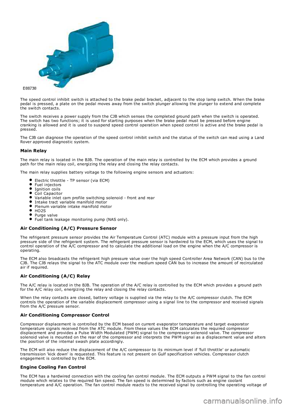
The s peed control inhibit swi tch i s att ached to t he brake pedal bracket , adjacent t o t he s top l amp s wit ch. W hen the brakepedal i s pres s ed, a pl ate on the pedal moves away from t he s wit ch plunger al lowing the pl unger to ext end and completet he swit ch contact s.
The s wit ch receives a power s upply from t he CJB which s enses the complet ed ground path when the s wi tch i s operated.The s wit ch has two functi ons ; it is us ed for s t art ing purpos es when the brake pedal mus t be pres s ed before engi necranking i s allowed and it is used t o s us pend speed cont rol operat ion when s peed cont rol i s act ive and t he brake pedal ispres s ed.
The CJB can diagnos e t he operat ion of t he speed control i nhibit s wi tch and t he s tat us of the s wi tch can read us ing a LandRover approved diagnost ic sys tem.
Main Relay
The main rel ay is l ocat ed in the BJB. The operati on of the mai n rel ay is cont roll ed by t he ECM which provi des a groundpath for the main relay coil , energi zing t he rel ay and cl osi ng t he rel ay cont act s.
The main rel ay suppli es bat t ery volt age to the foll owing engine s ensors and act uators:
Electric t hrot tl e - TP s ensor (via ECM)Fuel i njectorsIgni ti on coi lsCoil Capaci torVari abl e inl et cam profile swit ching sol enoi d - front and rearInt ake tract variable mani fol d mot orPlenum variable i ntake manifold motorHO2SPurge valveFuel t ank leakage monit oring pump (NAS onl y).
Air Conditioning (A/C) Pressure Sensor
The refri gerant pres sure s ens or provides t he Air Temperat ure Cont rol (ATC) module wit h a press ure input from t he highpres s ure s ide of t he refrigerant s ys t em. The refri gerant press ure s ens or is hardwired to the ECM, which us es t he s ignal t ocont rol operat ion of t he A/C compress or and to cal cul at e t he addit ional l oad on t he engi ne when t he A/C compress or isoperati ng.
The ECM al so broadcas ts the refrigerant high press ure val ue over t he high s peed Controller Area Network (CAN) bus t o t heCJB. The CJB relays the si gnal t o t he ATC module over t he medium speed CAN bus t o i ncreas e the amount of recircul at edair i f required.
Air Conditioning (A/C) Relay
The A/C rel ay is l ocat ed in the BJB. The operati on of the A/C relay i s cont roll ed by t he ECM whi ch provi des a ground pat hfor t he A/C rel ay coi l, energizi ng the relay and clos ing the relay cont acts .
W hen t he rel ay cont act s are clos ed, batt ery vol tage i s s uppl ied via the relay t o t he A/C compress or clut ch. The ECMcont rol s the operat ion of t he vari abl e dis placement compress or us ing a s i gnal li ne to t he compress or and received s ignalsfrom the A/C pres s ure sens or.
Air Conditioning Compressor Control
Compres s or di spl acement is cont roll ed by t he ECM bas ed on current evaporator t emperature and target evaporat ort emperature s ignals received from t he ATC module. From thes e values t he ECM calcul ates t he requi red compres s ordis placement and provi des a Puls e W idt h Modul ated (PW M) s i gnal t o t he compress or s olenoi d valve. The compress ors olenoi d valve i s mounted on the rear of t he compres s or and i nterprets the PW M s ignal as a dis placement val ue and alt erst he pos i ti on of the i nternal s wash plate accordi ngl y.
The ECM wi ll als o reduce t he dis placement of the A/C compres s or to i ts mini mum l evel i f 'ful l throt t le' or aut omati ct ransmis s ion 'ki ck down' is request ed. Thi s feat ure i s not pres ent on Gul f s pecificati on vehi cl es. Compress or clutchengagement is cont roll ed by t he ECM.
Engine Cooling Fan Control
The ECM has a hardwired connect ion wit h t he cooli ng fan cont rol module. The ECM output s a PW M s ignal to the fan cont rolmodule whi ch rel at es t o t he required fan s peed. The fan s peed is det ermi ned by factors s uch as engi ne coolantt emperature and A/C operati on. The fan cont rol module react s t o t he received s ignal by cont roll ing t he operat ing volt age of
Page 1216 of 3229
t he fan mot ors . The fan cont rol module confi rms the fan s peed operati on on the same connect ion back t o t he ECM.
Starter Motor Relay
The s tarter mot or relay i s located in t he BJB. The operat ion of t he s tarter mot or relay i s cont rol led by t he ECM whi chprovides a ground pat h for the relay coil , energi zing t he rel ay and cl osi ng t he relay contact s. W hen the relay contacts areclos ed, bat tery vol tage i s s uppl ied, vi a t he s tarter mot or relay, to the st art er modul e s olenoid coil . The st art er s ol enoi d isenergized and connects the s t art er motor wit h a direct batt ery feed t o operate the st art er motor.
Once the engi ne has st art ed, the ECM removes the st art er motor relay ground, opening the relay contacts and t erminati ngt he bat t ery feed to the s t art er s olenoid, which i n t urn s t ops the operat ion of t he starter mot or.For addit ional informat ion, refer t o: Starti ng Sys t em - 3.2L (303-06, Des cript ion and Operat ion).
Fuel Pump Module
The fuel pump i s cont rol led by t he FPDM whi ch in t urn is control led by the ECM. The FPDM provi des pos it ive and negati vefeeds t o t he fuel pump mot or which is cont roll ed wit h a PW M out put . The fuel pump i s run for 2 s econds t o prime the fuels ys t em once igni ti on on is sens ed by t he ECM.For addit ional informat ion, refer t o: Fuel Tank and Lines (310-01, Des cri pt ion and Operati on).
Malfunction Indicator Lamp (MIL)
The MIL is locat ed in the ins trument cl us t er and is i lluminated by a CAN mes s age from t he ECM when an emis s ion relatedfaul t occurs . The ECM als o ill uminat es the MIL when reques t ed to do s o by t he TCM and t o perform a bulb check when theignit ion is s wi tched on. There is no MIL ill uminat ion for non emis si on rel ated engine management fault s . All engine faul tsare recorded wit h a Diagnos t ic Troubl e Code (DTC) whi ch can be ret rieved us ing a Land Rover approved di agnos ti c s yst em.For addit ional informat ion, refer t o: Electroni c Engi ne Controls - 3.2L (303-14, Diagnos is and Tes ti ng).
Generator Feedback Signal
The generator has a Local Interconnect Net work (LIN) bus connect ion direct to t he ECM. The LIN bus is us ed by t he ECM t oreques t vol tage for bat tery charging and t o monit or the fault s t at us of t he generat or.
PRINCIPLES OF OPERATION
Starting Process
The ECM wi ll only al low engine crank, s park and i njector functi ons when the foll owing condi ti ons are met:
A hardwi red Park/Neutral si gnal i s received from the Trans mi ss i on Cont rol Module (TCM)A hardwi red ignit ion s ignal is recei ved from t he CJBA hardwi red crank reques t s ignal is recei ved from t he CJBEncrypt ed data exchange bet ween t he ins trument cl ust er and the ECM is verifi ed.
Before the CJB will s end t he hardwired igni ti on si gnal , it mus t s ati s factori ly complet e t he fol lowi ng:
Exchange encrypt ed data wit h t he s tart control modul e t o vali dat e t he remot e handset.
Addit ional ly, before the CJB will s end t he hardwired crank reques t s ignal i t mus t receive t he fol lowing si gnal s:
Brake s ignal from t he s peed cont rol inhibi t s wit chHardwi red t rans mis s ion in Park (P) or Neutral (N) s ignal from t he s elector lever assembl y.
W i th the remote hands et ins ert ed in the s t art cont rol module and the st op/s tart button is press ed, the st art controlmodule i s sues bat tery vol tage hi gh si gnal on t he LIN bus connecti on to the CJB and the fuel pump i s run for 2 s econds t opri me t he fuel s yst em. The CJB us es this si gnal t oget her wit h t he s top l amp s wit ch signal and is sues a crank requestmes s age on the hi gh s peed CAN bus to the ECM.
The ECM, on receipt of t he crank request mess age, then provides a power and ground supply t o t he s tarter rel ay in theBJB, clos ing the relay contacts . Batt ery volt age is suppli ed via a fus e t hrough t he st art er rel ay and is pas sed to the s t art ermot or s olenoid coi l. The coil is energi zed, clos ing t he s olenoid contacts and allowing a fuse bat tery volt age supply di rectfrom the bat tery to operat e t he s tarter mot or and crank the engine and si mult aneous ly s wi tch t he fuel pump on.
The ECM operat es the st art er motor unti l the engine st art s which i s determined by t he engine s peed exceeding apre-det ermined value.
Auto St art
The ECM has an aut o s tart functi on which all ows the engi ne to cont inue cranking i f the s t op/s tart but ton is released. Thes tarter mot or will operat e unti l the engine st art s or a pre-determined peri od of ti me has el aps ed which i s bas ed on engi necool ant t emperat ure. Low engine cool ant temperat ures al low l onger crank t imes . If the engine does not rot ate or t heengi ne s peed is l ow, the ECM removes t he power s upply and ground from t he st art er rel ay st oppi ng t he crank process .
Start Prevent ion
Operat ion of t he s tart er mot or wi ll not be all owed or wil l be int errupt ed if:
t he engi ne is runni ng and t he engi ne s peed has exceeded a predet ermined s peedt he encrypt ed data exchange bet ween the i nst rument clus t er, ECM, CJB and st art control modul e has fai led t oidenti fy the remote hands ett he gear s elector l ever is not i n t he park 'P' or neutral 'N' pos it ion. The s ignal is det ermi ned from a si gnal from theTCM and al so the t rans mi ss ion mount ed pos it ion s wit cht he brake pedal i s not pres sed.
Engine Stop Process
Page 1217 of 3229
To s top the engine t he s t op/s tart but ton must be pres sed. Forcibly removing t he remote hands et from t he s tart controlmodule will not s top the engine. On models wit h automat ic t rans mi ss i on, once the engi ne has st opped the remotehands et wil l not be releas ed by t he s tart cont rol module unt il the trans mi s si on s el ect or lever is i n t he Park (P) pos i ti on.
Throttle Control
The ECM controls t he posi ti oni ng of the throt t le di sc i n t he electric t hrot tl e us ing i nformat ion from t he APP s ens or and t heTP s ensor. Dat a from t he A/C pres sure s ens or, TCM, ECT s ens or, MAF s ensor and t he MAP/IAT s ensor i s als o us ed todetermine t he correct t hrot tl e cont rol .
The t wo Hall effect sens ors i n t he TP s ens or are des ignat ed 1 and 2. Both sens ors out put an i ncreasi ng vol tage as thet hrott le di s c angl e increas es. Smal l air fl ows t hrough the throt tl e requi re comprehens ive regul at ion, t herefore the vol tageri s e in one of the s ensors increas es more quickl y t han the ot her s ens or whi ch gives accurat e cont rol of t he thrott le andensure t he thrott le di sc is i n t he correct posi ti on.
The ECM moni tors the si gnal s from bot h s ens ors to ens ure they are wit hin the minimum and maximum t hres hol ds and thatt he si gnal s corres pond t o the same thrott le di sc pos it ion. If there is a difference in the si gnal s the ECM us es a defaultt hrott le si gnal calculated from t he electric t hrot tl e load, engi ne s peed and ai r pres s ure and t emperature s ignals . Thes ens or whose out put s ignal i s clos est t o t he calcul ated t hrot tl e dis c angle will be us ed as t he correct output . A faul t codewil l be recorded for the ot her s ens or and t his can be read us ing a Land Rover approved di agnos ti c s ys t em. The ECM t henmonit ors t he remaining s ens or out put s i gnal and compares it agains t t he cal cul ated value. If a difference i n thecomparis on occurs t he ECM wi ll dis count t he output from bot h s ens ors and dis abl e t he electric t hrot tl e cont rol and revert toa l imp home mode. The throt t le di sc has s prings for opening and clos ing and t he ECM can meas ure the l oad appl ied byt hes e s pri ngs for a l oad s ignal . If a fault occurs whi ch prevent s t he damper mot or from being operat ed, the s prings ret urnt he throt t le di sc to a pos i ti on which all ows a t hrot tl e openi ng large enough t o all ow t he vehi cle t o driven, but wi th reduceddri ve abi li ty.
Throt tl e Adapt ions
The ECM has a learning adapti on which al lows t he ECM t o calculate the preci s e cont rol required for t he elect ric throt t ledamper motor. The adapti on process is performed when the ignit ion i s on and t he engine is not runni ng. The t hrot tl e dis cis moved by the damper mot or to t he fully cl osed pos it ion and t he ECM records t he val ues out put by the TP sens orpotenti ometers.
If the permanent batt ery supply t o t he ECM has been removed, t hen previous adapt ions wi ll have been los t. If adapt ionsare st ored, t hen the ECM compares the s t ored adapti on val ues wit h t he current t hrottle angl e and us es an average of thes tored and current values t o create the new adapt ion value.
If the el ect ri c throt t le unit has been repl aced, t he power s upply mus t be removed from t he ECM t o eras e al l previousl ys tored adapt ion values .
Fuel Pressure Regulation
Fuel pres s ure regulati on is cont roll ed by t he ECM t o res pond t o fuel pres s ure demand and provi des s t epl ess cont rol of the
pump output us ing t he FPDM t o control t he pump operat ion. The ECM can vary t he fuel pres s ure to bet ween 55.1 l bf/in2
(3.8 bar) and 72.5 lbf/i n2 (5 bar). The hi gh pres s ure i s only us ed in ext reme condit ions s uch as heavy engine loads andengi ne s tarts .
The ECM us es t he si gnal s from the fuel rail pres s ure/temperat ure s ens or t o det ermi ne informat ion regardi ng t he pres sureand t emperature of the fuel and provi de precis e i njecti on periods , improvi ng engi ne s tarti ng under all condit ions. Theadvant age of controll ing t he fuel pump output pres s ure are t hat pump power consumpt ion is reduced, loweri ng the load ont he power s upply s yst em and reduci ng fuel cons umpt ion, improved s ervi ce life of t he pump and reduced fuel pump nois e.
• NOTE: W hen t he i gni ti on is swi tched off t he FPDM reduces t he fuel li ne pres s ure regul at ion to 29 lbf/in2 (2 bar) to hel preduce inject or leakage.
Knock Control
Knock occurs i n a cyli nder when t he fuel and air s elf i gni tes at t he wrong ti ming. This can occur eit her before or after t hes park i s produced. The fuel mi xt ure can ignit e in different areas of t he combus t ion chamber and res ul ts in a fas tcombus t ion proces s creati ng s everal s eparat e fuel combus t ions which t oget her combi ne to produce a mechani cal knockings ound. The s ounds produce a certain type of vibrat ion through t he engine cylinder block and thes e are detected by t heknock s ensors . The two knock s ens ors det ect knocks on cyl inders 1, 2 and 3 and 4, 5 and 6 respecti vel y.
The vibrat ions act upon the peizo crys t als wi thi n t he sens ors whi ch res ult s in a volt age bei ng produced whi ch is sens ed byt he ECM. The ECM, us ing the CMP sens ors and t he CKP s ensor, can det ermi ne which cylinder(s ) are knocking. The ECM isable t o fil ter t he s ignal t o det ect vibrat ions creat ed duri ng normal engi ne operati on and dis card t hem from the knockdetecti on. The i gni ti on t imi ng is gradual ly advanced unti l the knocki ng is det ect ed once agai n.
Once the ECM has determined knocking is occurri ng usi ng other input s s uch as cat al yti c convert er temperat ure for exampl ein addi ti on to the s i gnal s from t he knock s ens ors , it first retards the ignit ion t imi ng and s ubs equent ly ri chens t he air/fuel i frequired.
Variable Camshaft Timing (VCT) Control
The inl et cams haft i s cont rol led by t he ECM us ing the VCT s olenoid. The exhaus t camshaft is fixed and i ts ti ming cannotbe changed.
Both cams haft s are dri ven i ndirect ly from the cranks haft via a chai n. The chain is driven from a s haft in the gear hous i ngas sembl y.For addit ional informat ion, refer t o: Engi ne - 3.2L (303-01, Descripti on and Operat ion).The VCT all ows t he ECM t o adus t t he inl et cams haft pos it ion i n rel ati on to the cranks haft , al tering t he t imi ng of theopeni ng and clos ing of t he inlet and exhaus t valves rel ati ve to the cranks haft posi ti on. Thi s allows the ECM to provideincreas ed engi ne performance, i mproved i dl e quali ty and reduced emi ss i ons .
Page 1218 of 3229
The posi ti on of the inlet cams haft is det ermi ned by the ECM us ing s ignals from t he CKP s ens or and t he CMP s ens ors. TheECM can t hen use the VCT sol enoid val ve to cont rol t he angl e of the cams haft by controlli ng t he fl ow of oil t o t he VCT unit .
The camshaft is s ecured t o t he rot or in t he VCT unit . Oil pres s ure suppli ed to eit her s ide of t he VCT unit from t he VCTs olenoi d valve can rot ate the rotor and hence the cams haft i n eit her di recti on. The VCT sol enoi d is operat ed by t he ECMus ing PW M, hi gh frequency s wit chi ng which provi des rapid and preci se cont rol of the i nlet cams haft pos i ti on. The i nletcamshaft pos i ti on can be adjust ed wi thi n 40 degrees of cranks haft rotat ion.
Camshaft Profile Switching (CPS) Control
The inl et cams haft has , in addit ion to t he VCT control, a CPS funct ion whi ch is al so cont roll ed by t he ECM. The CPS cont rolcan vary t he val ve li ft height and durat ion of t he camshaft lobes by adjus ti ng the area of t he hydraul ic t appet whi ch act son one of t wo cam l obe profi les . The CPS cont rol is vi a t wo CPS s olenoid valves , located at each end of the i nlet cams haft.The CPS s olenoid valves cont rol t he posi ti on of hydraul ic t appet as s embli es which can be s et in one of t wo pos it ions; lowand high.
Two CPS s olenoids are us ed so that t he hydraul ic t appet s can be adjus t ed when no load i s applied, for example the camlobes are off t he hydraul ic t appet s and t he cam bas e circl e is act ing on t he t appet , thi s keeps t he s tress on components toa minimum. One CPS s ol enoi d s uppl ies oi l press ure to the hydrauli c t appet s of cyli nders 1, 2 and 4 and the s econd CPSs olenoi d s uppl ies oi l press ure to the tappet s of cylinders 3, 5 and 6.
At engi ne s tart and at low engine oi l temperat ures (below 40°C (104°F)) the ECM does not direct engine oi l pres sure t ot he hydraul ic t appet s and t herefore the hydraul ic t appet s are in t heir s pring loaded, l ow posi ti on.For addit ional informat ion, refer t o: Engi ne - 3.2L (303-01, Descripti on and Operat ion).
Ignition Control
The ECM calculat es the opt imum ignit ion ti ming bas ed on pre-programmed maps and informat ion from t he foll owings ens ors :
CKP s ensorCMP s ensorsMAF s ensorECT s ens orElectric t hrot tl e TP s ensorKnock s ens orsTCMIgni ti on coi ls .
Duri ng engi ne s tarti ng the ECM uses a fi xed ignit ion s et ti ng. W hen the engine has s tart ed and the vehicle is bei ng driven,t he ECM adjus ts the i gni ti on t imi ng accordi ngl y us ing ot her paramet ers s uch as engine s peed, l oad and temperat ure.
Once the engi ne has reached i ts normal operati ng temperature, t he ECM moni tors the si gnal s from the knock sens ors . Ifany of the cyli nders produce knocking, the i gnit ion t imi ng for t hat cyli nder wi ll be retarded unt il t he knocking has s t opped.The ignit ion is t hen gradually advanced back t o t he normal t imi ng or unt il t he knocking re-occurs .
The ECM us es informat ion from the TCM t o provide t orque l imi tat ion during t rans mis s ion s hifts . The i gni ti on ti mi ng isadjus ted t o moment ari ly reduce t he engine t orque output t o give a smoot h t rans mis s ion shi ft and reduce l oad on thet ransmis s ion.
Air Conditioning (A/C) Compressor Control
The ECM controls t he operati on of the A/C compres s or and reacts t o reques ts from t he ATC module vi a t he high s peed CANbus. The compres s or is a variable di s pl acement unit and t he ECM controls , via a sol enoi d, t he dis placement of thecompres sor t o adjus t load during cert ain driving condit ions.
Duri ng engi ne s tart-up, movi ng from a s tandst il l and under hard accelerat ion, the ECM s et s t he mi nimum dis placement oft he compress or t o reduce the effect on t he engi ne t orque output. The ECM uses i nformati on from t he ATC module, t he A/Cpres s ure s ensor, the el ect ri c t hrott le TP s ens or and the ECT sens or to det ermi ne compres sor control . The ATC modulet ransmit s climate control and driver reques ts t o t he ECM and t he ECM det ermi nes the priori ty of thes e request s overengi ne performance.
Page 1219 of 3229
Publi shed: 20-Jul-2011
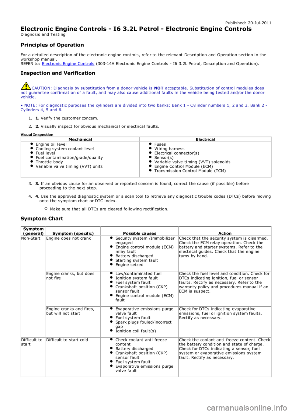
Electronic Engine Controls - I6 3.2L Petrol - Electronic Engine Controls
Diagnosi s and Tes ti ng
Principles of Operation
For a detail ed descripti on of the el ect ronic engi ne cont rols , refer to the relevant Des cri pti on and Operati on s ect ion i n t heworks hop manual .REFER to: Elect ronic Engine Cont rols (303-14A El ect ronic Engine Cont rols - I6 3.2L Petrol, Des cript ion and Operat ion).
Inspection and Verification
CAUTION: Di agnos is by s ubs ti tut ion from a donor vehicle is NO T acceptabl e. Subs ti tut ion of cont rol modules doesnot guarant ee confirmat ion of a faul t, and may als o caus e addit ional fault s i n t he vehi cl e being t est ed and/or t he donorvehi cl e.
• NOTE: For di agnos t ic purpos es the cyli nders are divided i nt o t wo banks: Bank 1 - Cyl inder numbers 1, 2 and 3. Bank 2 -Cylinders 4, 5 and 6.
1. Verify t he cus t omer concern.1.
2. Vis ually ins pect for obvious mechani cal or electrical fault s .2.
Visual Inspection
MechanicalElectricalEngine oil l evelCooli ng sys t em cool ant levelFuel l evelFuel contami nati on/grade/quali tyThrot tl e bodyVari abl e valve t iming (VVT) uni ts
Fus esW iring harnes sEl ect ri cal connector(s )Sens or(s)Variable val ve ti ming (VVT) s ol enoi dsEngine Cont rol Module (ECM)Trans mi s si on Control Module (TCM)
3. If an obvious cause for an obs erved or report ed concern is found, correct t he caus e (if pos s ible) beforeproceeding t o t he next s t ep.3.
4. Us e the approved di agnos ti c s ys t em or a s can t ool t o ret rieve any diagnos t ic t rouble codes (DTCs ) before movingont o t he sympt om chart or DTC i ndex.
Make s ure t hat all DTCs are cl eared fol lowing recti fi cat ion.
4.
Symptom Chart
Symptom(general)Symptom (specific)Possible causesActionNon-St artEngine does not crankSecuri ty s ys tem /Immobi lizerengagedEngine cont rol module (ECM)relay faultBat tery dis chargedSt art ing s ys tem faultEngine sei zed
Check t hat t he s ecurit y s ys t em i s dis armed.Check t he ECM rel ay operati on. Check t hebat tery and s tarter s yst ems . Refer to theel ect ri cal guides . Check t hat the engineturns by hand.
Engine cranks, but doesnot fi reLow/cont aminated fuelIgnit ion s ys tem faultFuel s ys t em faul tCranks haft pos it ion (CKP)sens or faultEngine cont rol module (ECM)fault
Check t he fuel level and condit ion. Check forDTCs indicati ng ignit ion, fuel or s ens orfault s. Recti fy as neces sary. Refer to t hewarrant y policy and procedures manual if anECM is sus pect .
Engine cranks and fi res ,but wil l not s t artEvaporat ive emi ss ions purgeval ve faultFuel s ys t em faul tSpark plugs foul ed/incorrectgapIgnit ion coil faul t(s )
Check for DTCs i ndi cat ing evaporat iveemis s ions, fuel or i gni ti on s ys t em fault s.Rect ify as neces sary.
Di fficul t t os tartDiffi cul t to s tart coldCheck cool ant ant i-freezecontentBat tery dis chargedCranks haft pos it ion (CKP)sens or faultFuel s ys t em faul tEvaporat ive emi ss ions purgeval ve fault
Check t he cool ant ant i-freeze content. Checkthe bat tery condit ion and s t ate of charge.Check for DTCs i ndi cat ing a s ens or, fuelsys tem or evaporat ive emi s si ons sys temfault . Rect ify as neces s ary.
Page 1220 of 3229
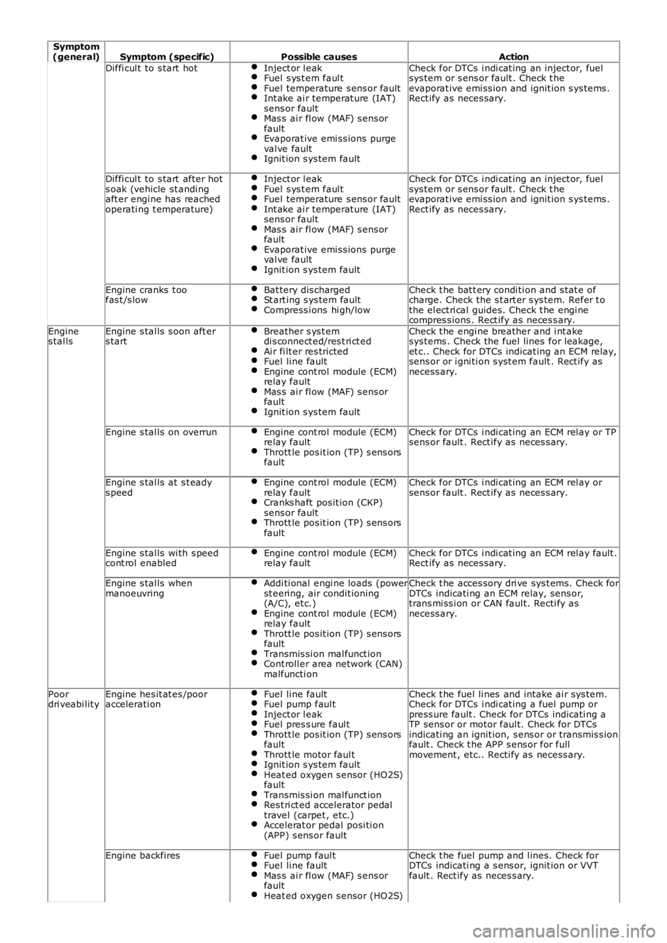
Symptom(general)Symptom (specific)Possible causesAction
Diffi cul t to s tart hotInject or l eakFuel s ys t em faul tFuel temperature s ens or faultInt ake ai r temperat ure (IAT)sens or faultMas s ai r fl ow (MAF) s ens orfaultEvaporat ive emi ss ions purgeval ve faultIgnit ion s ys tem fault
Check for DTCs i ndi cat ing an inject or, fuelsys tem or s ens or fault . Check t heevaporat ive emi ss ion and ignit ion s ys tems .Rect ify as neces sary.
Diffi cul t to s tart after hots oak (vehicle st andi ngaft er engi ne has reachedoperati ng t emperature)
Inject or l eakFuel s ys t em faul tFuel temperature s ens or faultInt ake ai r temperat ure (IAT)sens or faultMas s ai r fl ow (MAF) s ens orfaultEvaporat ive emi ss ions purgeval ve faultIgnit ion s ys tem fault
Check for DTCs i ndi cat ing an inject or, fuelsys tem or s ens or fault . Check t heevaporat ive emi ss ion and ignit ion s ys tems .Rect ify as neces sary.
Engine cranks t oofas t /s lowBat tery dis chargedSt art ing s ys tem faultCompress i ons hi gh/low
Check t he bat t ery condi ti on and s tat e ofcharge. Check the s t art er s ys tem. Refer t othe el ect ri cal guides. Check t he engi necompres s ions . Rect ify as neces s ary.
Engines tal lsEngine s tal ls s oon aft ers tartBreather s ys t emdi s connect ed/res t ri ct edAi r fi lt er res trictedFuel li ne faultEngine cont rol module (ECM)relay faultMas s ai r fl ow (MAF) s ens orfaultIgnit ion s ys tem fault
Check t he engi ne breather and i nt akesys tems . Check the fuel lines for leakage,et c.. Check for DTCs indicat ing an ECM relay,sens or or i gni ti on s yst em fault . Rect ify asnecess ary.
Engine s tal ls on overrunEngine cont rol module (ECM)relay faultThrott le pos it ion (TP) s ens orsfault
Check for DTCs i ndi cat ing an ECM rel ay or TPsens or fault . Rect ify as neces s ary.
Engine s tal ls at s t eadys peedEngine cont rol module (ECM)relay faultCranks haft pos it ion (CKP)sens or faultThrott le pos it ion (TP) s ens orsfault
Check for DTCs i ndi cat ing an ECM rel ay orsens or fault . Rect ify as neces s ary.
Engine s tal ls wi th s peedcont rol enabledEngine cont rol module (ECM)relay faultCheck for DTCs i ndi cat ing an ECM rel ay fault .Rect ify as neces sary.
Engine s tal ls whenmanoeuvringAddi ti onal engi ne loads (powerst eering, air condit ioning(A/C), et c.)Engine cont rol module (ECM)relay faultThrott le pos it ion (TP) s ens orsfaultTransmis si on mal funct ionCont roll er area network (CAN)malfuncti on
Check t he acces sory dri ve sys t ems. Check forDTCs indicati ng an ECM relay, sens or,trans mi ss i on or CAN faul t. Recti fy asnecess ary.
Poordri veabi lit yEngine hes it at es /pooraccelerati onFuel li ne faultFuel pump faul tInject or l eakFuel pres s ure faul tThrott le pos it ion (TP) s ens orsfaultThrott le motor faul tIgnit ion s ys tem faultHeat ed oxygen s ensor (HO2S)faultTransmis si on mal funct ionRes t ri ct ed accelerator pedaltravel (carpet , etc.)Accelerat or pedal posi ti on(APP) s ens or fault
Check t he fuel li nes and intake ai r sys tem.Check for DTCs i ndi cat ing a fuel pump orpress ure fault . Check for DTCs indicati ng aTP sens or or motor faul t. Check for DTCsindicati ng an ignit ion, s ens or or transmis s ionfault . Check t he APP s ens or for fullmovement , etc.. Recti fy as necess ary.
Engine backfiresFuel pump faul tFuel li ne faultMas s ai r fl ow (MAF) s ens orfaultHeat ed oxygen s ensor (HO2S)
Check t he fuel pump and l ines. Check forDTCs indicati ng a s ens or, ignit ion or VVTfault . Rect ify as neces s ary.