LAND ROVER FRELANDER 2 2006 Repair Manual
FRELANDER 2 2006
LAND ROVER
LAND ROVER
https://www.carmanualsonline.info/img/64/57251/w960_57251-0.png
LAND ROVER FRELANDER 2 2006 Repair Manual
Trending: ECU, oil level, oil pressure, refrigerant type, airbag, technical data, ABS
Page 1191 of 3229
Publi s hed: 11-May-2011
Evaporative Emissions - Fuel Tank Leakage Monitoring Pump Filter
Removal and Inst all ati on
Removal
• NOTE: Removal s t eps in t his procedure may cont ain i nst all ati on det ail s.
Di sconnect t he bat t ery ground cable.
Refer t o: Specificati ons (414-00 Bat tery and Charging Sys tem -
General Informat ion, Specificati ons).
1.
2. W ARNING: Do not work on or under a vehi cle s upported onl y
by a jack. Al ways support t he vehi cl e on s afet y s tands .
Rais e and s upport t he vehi cl e.
2.
Remove t he rear wheel.
Refer t o: W heel and Ti re (204-04 W heel s and Tires, Removal and
Inst all at ion).
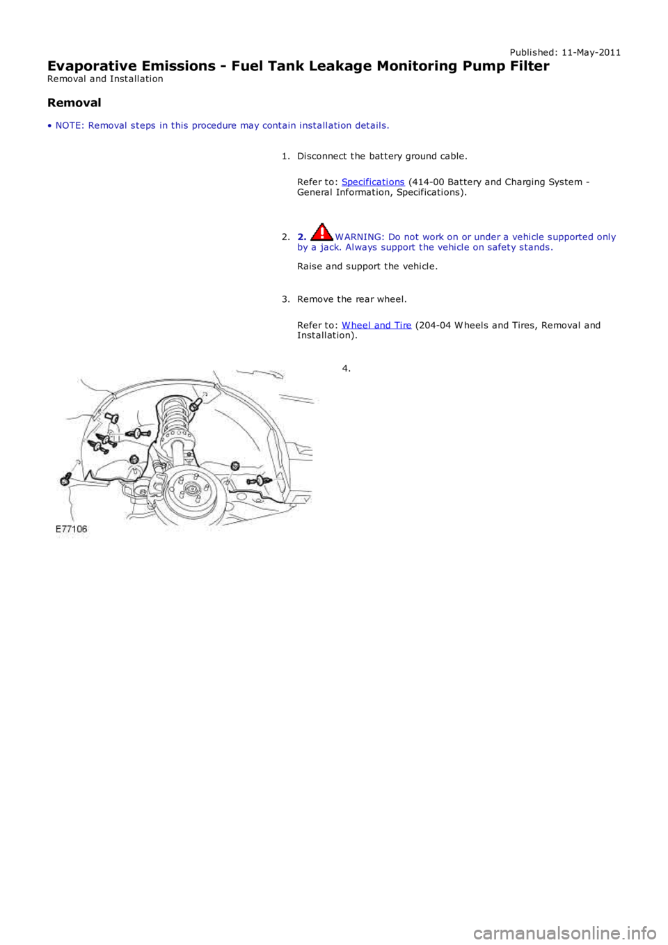
3. 4.
Page 1192 of 3229
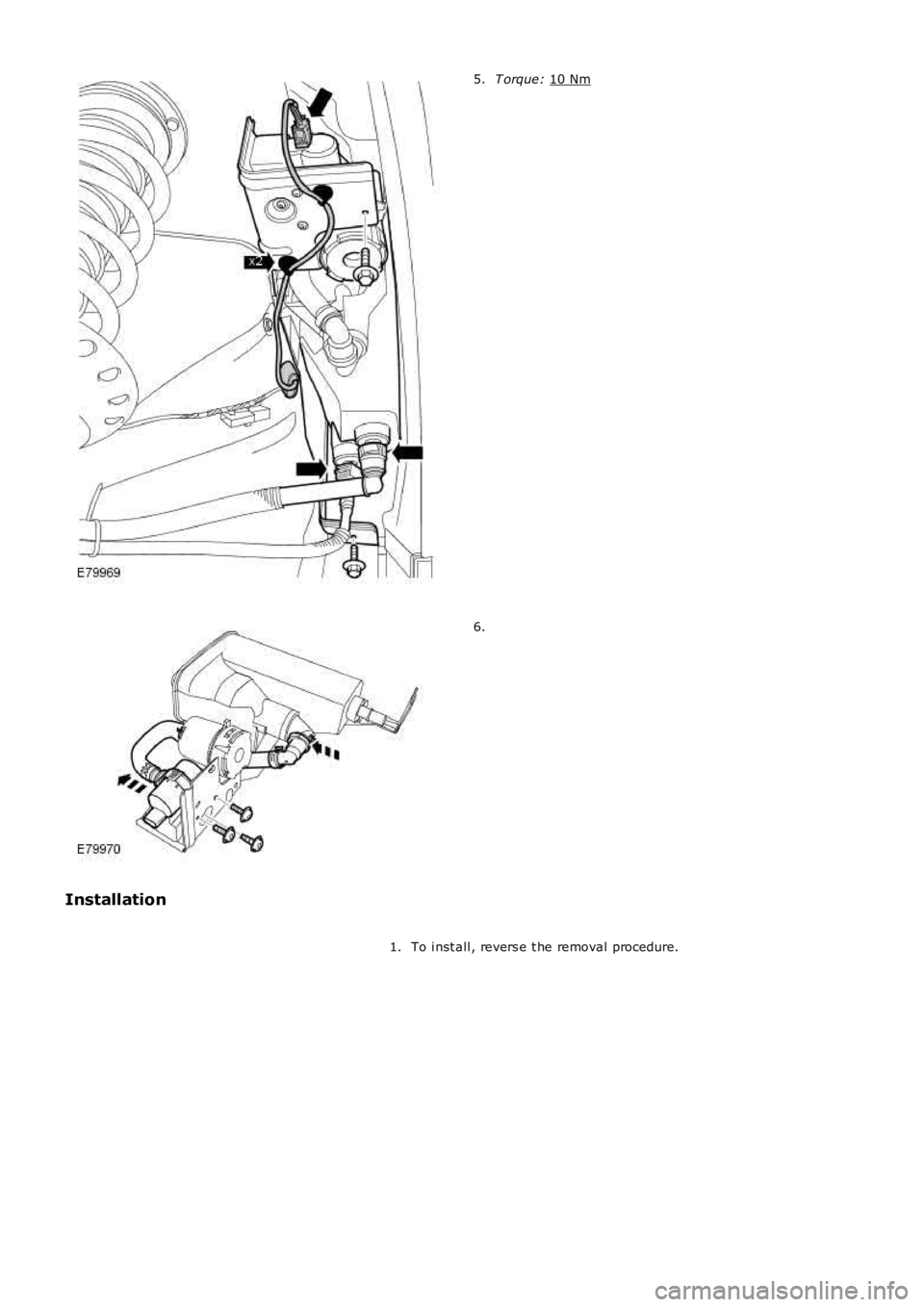
T orque:
10 Nm 5.
6.
Installation To i nst all , revers e t he removal procedure.
1.
Page 1193 of 3229
Publ is hed: 12-Dec-2011
Evaporative Emissions - Fuel Tank Leakage Monitoring Pump
Removal and Inst all ati on
Removal
• NOTE: Removal s t eps in t his procedure may cont ain i nst all ati on det ail s.
Di sconnect t he bat t ery ground cable.
Refer t o: Specificati ons (414-00 Bat tery and Charging Sys tem -General Informat ion, Specificati ons).
1.
2. W ARNING: Do not work on or under a vehi cle s upported onl yby a jack. Al ways support t he vehi cl e on s afet y s tands .
Rais e and s upport t he vehi cl e.
2.
Remove t he rear wheel.
Refer t o: W heel and Ti re (204-04 W heel s and Tires, Removal andInst all at ion).
3.
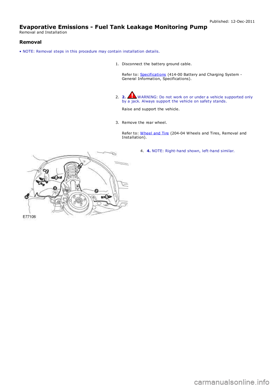
4. NOTE: Right-hand s hown, l eft-hand s imi lar.4.
Page 1194 of 3229
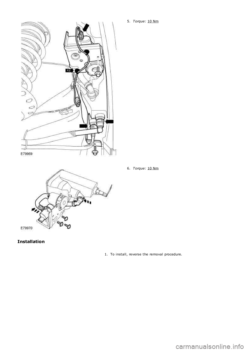
T orque:
10 Nm 5.
T orque:
10 Nm 6.
Installation To i nst all , revers e t he removal procedure.
1.
Page 1195 of 3229
Publi s hed: 11-May-2011
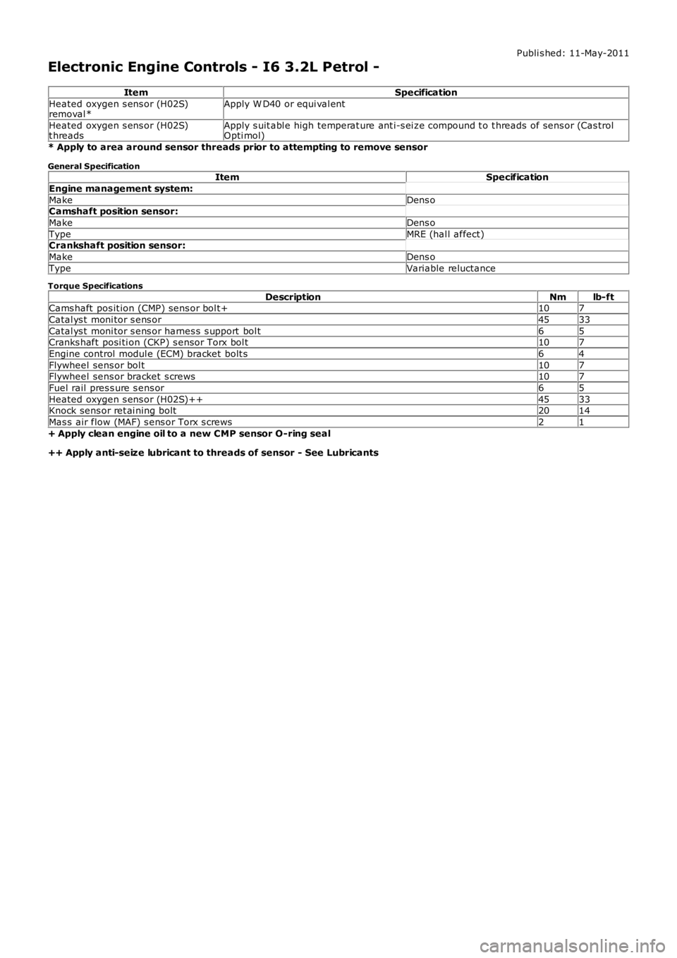
Electronic Engine Controls - I6 3.2L Petrol -
ItemSpecification
Heated oxygen s ens or (H02S)removal *Apply W D40 or equi val ent
Heated oxygen s ens or (H02S)t hreadsApply s uit abl e high temperat ure ant i-s ei ze compound t o t hreads of sens or (Cas trolOpti mol)
* Apply to area around sensor threads prior to attempting to remove sensor
General SpecificationItemSpecification
Engine management system:
MakeDens oCamshaft position sensor:
MakeDens o
TypeMRE (hal l affect)Crankshaft position sensor:
MakeDens o
TypeVariable reluctance
Torque Specifications
DescriptionNmlb-ftCams haft pos it ion (CMP) sens or bol t+107
Catal ys t moni tor s ens or4533
Catal ys t moni tor s ens or harnes s s upport bol t65Cranks haft posi ti on (CKP) s ensor Torx bol t107
Engine control modul e (ECM) bracket bolt s64
Flywheel sens or bol t107Flywheel sens or bracket s crews107
Fuel rail pres s ure s ens or65
Heated oxygen s ens or (H02S)++4533Knock sens or ret ai ning bolt2014
Mas s air flow (MAF) s ens or Torx s crews21
+ Apply clean engine oil to a new CMP sensor O-ring seal
++ Apply anti-seize lubricant to threads of sensor - See Lubricants
Page 1196 of 3229
Publi s hed: 11-May-2011
Electronic Engine Controls - I6 3.2L Petrol - Electronic Engine Controls
Des cript ion and Operat ion
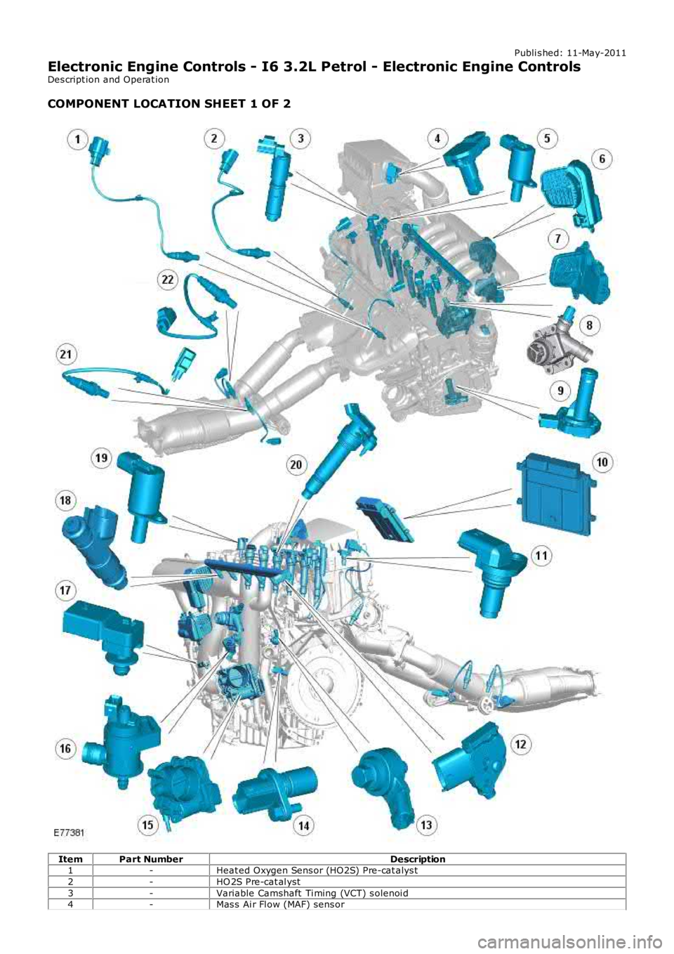
COMPONENT LOCATION SHEET 1 OF 2
ItemPart NumberDescription1-Heat ed Oxygen Sens or (HO2S) Pre-cat alys t
2-HO 2S Pre-cat al yst
3-Variable Camshaft Ti ming (VCT) s olenoi d4-Mas s Ai r Fl ow (MAF) sens or
Page 1197 of 3229
5-Cams haft Profi le Swi tching (CPS) sol enoid - rear
6-Pl enum variabl e int ake manifol d valve
7-Intake t ract vari abl e int ake manifol d valve8-Engine Cool ant Temperat ure (ECT) sens or
9-Engine oi l level/temperat ure s ens or
10-Engine Cont rol Module (ECM)11-Cams haft Pos it ion (CMP) s ens or (2 off)
12-Fuel rai l t emperat ure/press ure s ens or
13-Knock s ens ors (2 off)14-Cranks haft Pos it ion (CKP) sens or
15-El ect ri c thrott le
16-Purge val ve17-Mani fold Abs olut e Pres s ure (MAP) s ens or
18-Injectors (6 off)
19-CPS sol enoid - Front20-Ignit ion coil (6 off)
21-HO 2S Pos t -catal ys t
22-HO 2S Pos t -catal ys t
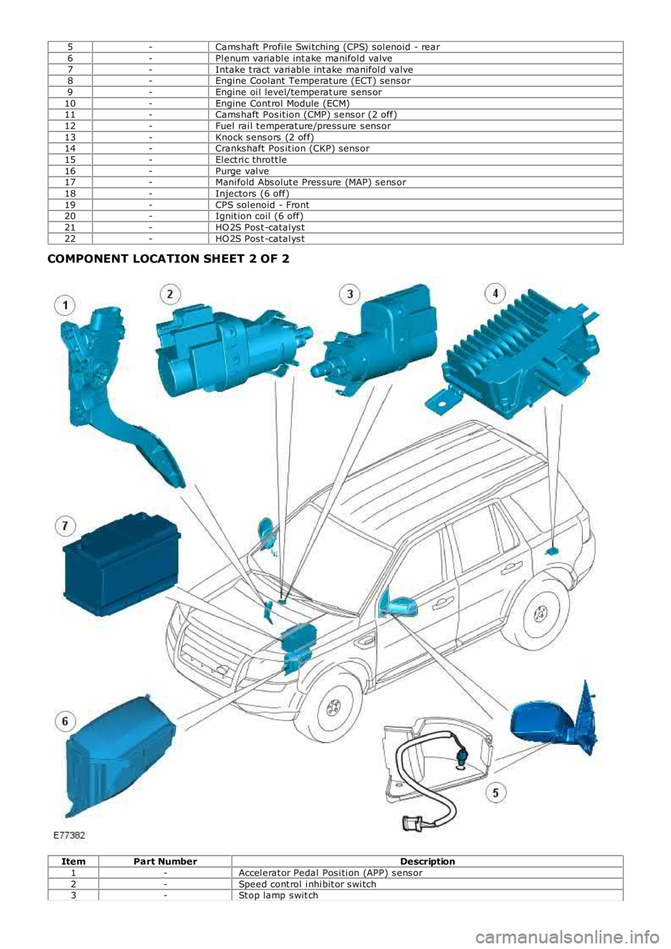
COMPONENT LOCATION SHEET 2 OF 2
ItemPart NumberDescription
1-Accel erat or Pedal Pos i ti on (APP) s ens or
2-Speed cont rol i nhi bit or s wi tch3-St op lamp s wit ch
Page 1198 of 3229
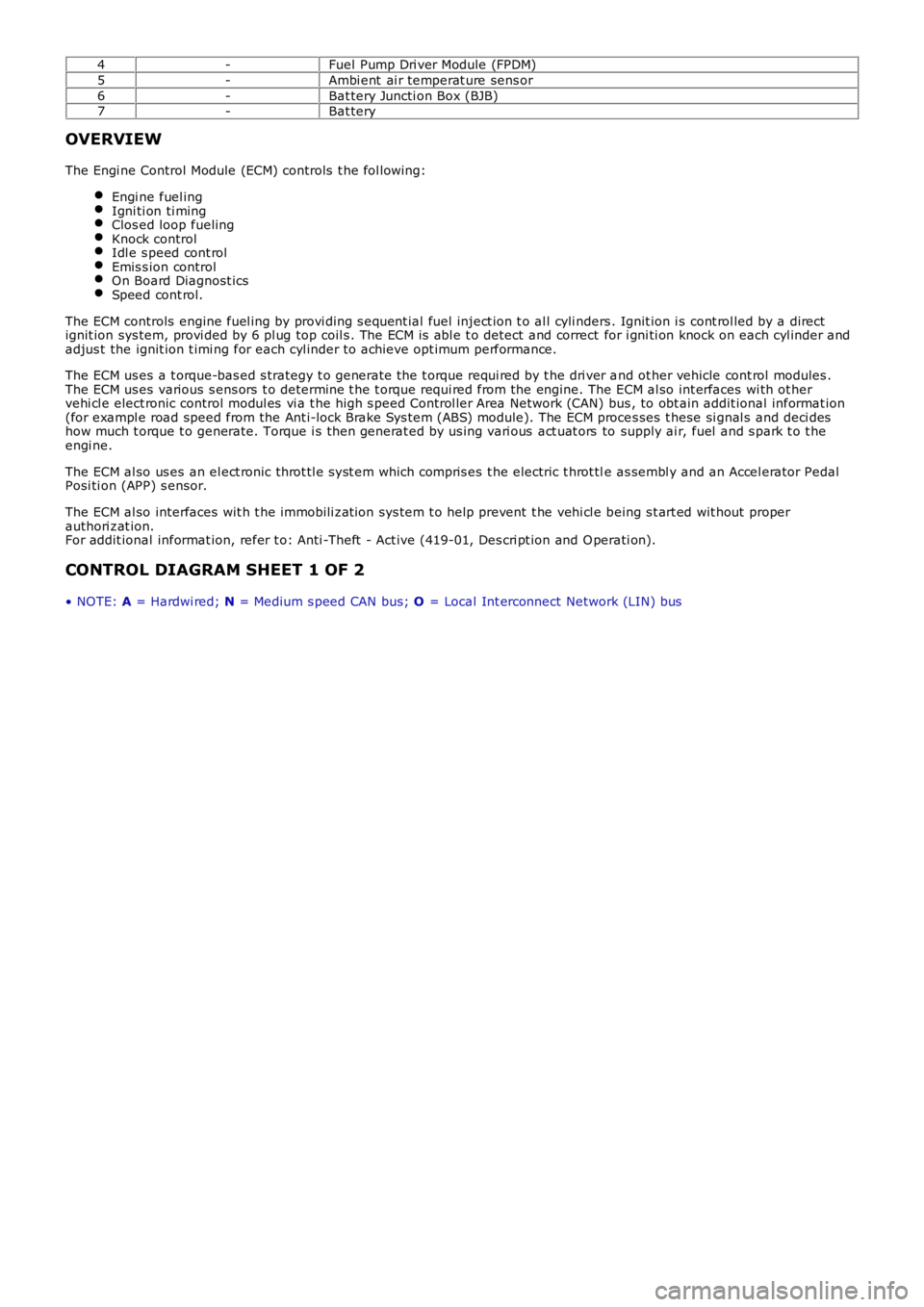
4-Fuel Pump Dri ver Module (FPDM)
5-Ambi ent ai r temperat ure sens or
6-Bat tery Juncti on Box (BJB)7-Bat tery
OVERVIEW
The Engi ne Control Module (ECM) controls t he fol lowing:
Engi ne fuel ingIgni ti on ti mingClos ed loop fuelingKnock controlIdl e s peed cont rolEmis s ion controlOn Board Diagnost icsSpeed cont rol.
The ECM controls engine fuel ing by provi ding s equent ial fuel inject ion t o al l cyli nders . Ignit ion i s cont rol led by a directignit ion sys tem, provi ded by 6 pl ug top coil s . The ECM is abl e t o detect and correct for i gni ti on knock on each cyl inder andadjus t the ignit ion t imi ng for each cyl inder to achieve opt imum performance.
The ECM us es a t orque-bas ed s trategy t o generate the t orque requi red by t he dri ver and ot her vehicle cont rol modules .The ECM us es various s ens ors t o determine t he t orque requi red from the engine. The ECM al so int erfaces wi th ot hervehi cl e elect ronic control modul es vi a t he high s peed Control ler Area Network (CAN) bus , to obt ain addit ional informat ion(for exampl e road speed from the Ant i-lock Brake Sys tem (ABS) module). The ECM proces ses t hese si gnal s and deci deshow much t orque t o generate. Torque i s t hen generat ed by us ing vari ous act uat ors to supply ai r, fuel and s park t o t heengi ne.
The ECM al so us es an el ect ronic throt tl e s yst em which compris es t he electric t hrot tle as sembl y and an Accel erator PedalPosi ti on (APP) s ensor.
The ECM al so interfaces wit h t he immobili zat ion sys tem t o help prevent t he vehi cl e being s t art ed wit hout properauthori zat ion.For addit ional informat ion, refer t o: Anti -Theft - Act ive (419-01, Des cri pt ion and Operati on).
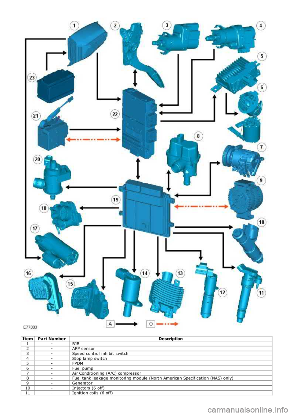
CONTROL DIAGRAM SHEET 1 OF 2
• NOTE: A = Hardwi red; N = Medium s peed CAN bus; O = Local Int erconnect Network (LIN) bus
Page 1199 of 3229
ItemPart NumberDescription
1-BJB2-APP s ens or
3-Speed cont rol i nhi bi t s wit ch
4-St op lamp swit ch5-FPDM
6-Fuel pump
7-Ai r Condit ioni ng (A/C) compress or8-Fuel tank l eakage monit ori ng module (Nort h American Specificati on (NAS) onl y)
9-Generat or
10-Injectors (6 off)11-Ignit ion coils (6 off)
Page 1200 of 3229
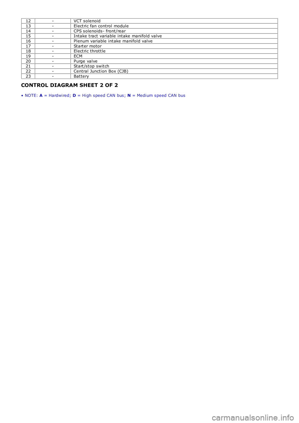
12-VCT s olenoid
13-El ect ri c fan control modul e
14-CPS s olenoids - front/rear15-Intake t ract variable int ake mani fol d valve
16-Pl enum variable int ake mani fol d val ve
17-St art er motor18-El ect ri c throt t le
19-ECM
20-Purge val ve21-St art /s t op swit ch
22-Central Juncti on Box (CJB)
23-Bat tery
CONTROL DIAGRAM SHEET 2 OF 2
• NOTE: A = Hardwi red; D = Hi gh s peed CAN bus ; N = Medi um s peed CAN bus
Trending: alarm, jump start terminals, recommended oil, fuel, oil level, radio controls, dimensions
