LAND ROVER FRELANDER 2 2006 Repair Manual
Manufacturer: LAND ROVER, Model Year: 2006, Model line: FRELANDER 2, Model: LAND ROVER FRELANDER 2 2006Pages: 3229, PDF Size: 78.5 MB
Page 1751 of 3229
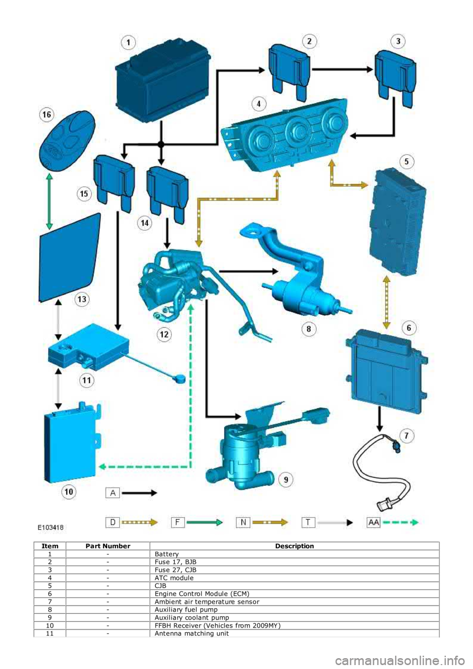
ItemPart NumberDescription
1-Bat tery2-Fus e 17, BJB
3-Fus e 27, CJB
4-ATC modul e5-CJB
6-Engine Cont rol Modul e (ECM)
7-Ambi ent ai r temperat ure sens or8-Auxil iary fuel pump
9-Auxil iary coolant pump
10-FFBH Receiver (Vehicles from 2009MY )11-Ant enna matching unit
Page 1752 of 3229
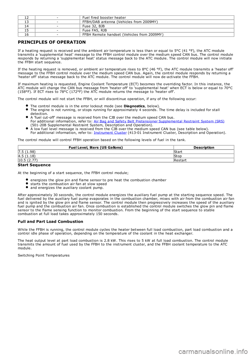
12-Fuel fi red boos ter heat er
13-FFBH/DAB ant enna (Vehicles from 2009MY )
14-Fus e 32, BJB15-Fus e FA5, RJB
16-FFBH Remot e hands et (Vehi cl es from 2009MY )
PRINCIPLES OF OPERATION
If a heat ing reques t i s received and t he ambient air t emperature is les s t han or equal to 5°C (41 °F), t he ATC modulet ransmit s a 'supplement al heat' mes s age to the FFBH control modul e over the medi um speed CAN bus . The control modul eres ponds by ret urning a 's uppl ement al heat ' st atus mess age back to the ATC modul e. The control modul e wi ll now i nit iatet he FFBH st art s equence.
If the heati ng reques t is removed, or ambient air t emperat ure ris es t o 8°C (46 °F), the ATC modul e t rans mit s a 'heat er off'mes s age to t he FFBH cont rol module over t he medium s peed CAN bus . Again, t he cont rol module res ponds by returni ng a'heater off' s tat us mes sage back to the ATC modul e. The cont rol module wi ll now de-act ivate the FFBH.
If maxi mum heat ing i s reques ted, Engi ne Cool ant Temperature (ECT) becomes the overriding factor. In t his i nst ance, t heATC module wil l change the CAN bus mes sage from 'heater off' to 's uppl emental heat ' when ECT is bel ow or equal t o 70°C(158°F). If ECT ri ses to 78°C (172°F) t he ATC module returns the mess age t o 'heater off'.
The cont rol module wil l not s t art t he FFBH, or wil l dis cont inue operat ion, if any of the foll owing occur:
The cont rol module is i n t he error l ockout mode (see Diagnostics, below).The engi ne is not runni ng, or s t ops running for approxi mately 4 s econds . The ti me delay i s included for s t alldetecti on.A 'fuel cut -off' mes s age is recei ved from t he CJB over t he medium s peed CAN bus .For addit ional informat ion, refer t o: Air Bag and Safet y Belt Pretens ioner Supplement al Res traint Syst em (SRS)(501-20B Supplement al Res t raint Sys tem, Des cript ion and O perati on).A l ow fuel l evel mes s age is recei ved from t he CJB over t he medium s peed CAN bus (s ee t abl e below).For addit ional informat ion, refer t o: Ins t rument Clus ter (413-01 Inst rument Cl us t er, Des cript ion and Operat ion).
The cont rol module wil l control FFBH operat ion bas ed on t he fol lowi ng levels of fuel i n the tank.
Fuel Level, liters (US Gallons)Description
7.5 (1.98)St art
4.5 (1.18)St op10.5 (2.77)Res tart
Start Sequence
At t he begi nni ng of a s tart s equence, t he FFBH cont rol module;
energizes t he glow pi n and flame s ens or t o pre heat the combust ion chambers tarts t he combust ion ai r fan at s l ow s peedand energizes t he auxi liary cool ant pump.
Aft er approxi matel y 30 s econds , the control modul e energizes t he auxi li ary fuel pump at t he s tarti ng s equence s peed. Thefuel deli vered by the auxil iary fuel pump evaporates i n t he combus t ion chamber, mi xes wi th air from the combus ti on air fanand is ignit ed by t he glow pi n and fl ame s ensor. The cont rol module t hen progres s ively increases t he s peed of the auxil iaryfuel pump and t he combus t ion ai r fan. Once combus ti on is est ablis hed t he cont rol module swi tches t he glow pi n and fl ames ens or t o the fl ame s ens i ng functi on to monit or combus ti on. From t he begi nni ng of the st art s equence t o s tabl ecombus t ion at full load t akes approxi mately 150 seconds .
Full and Part Load Combustion
W hi le t he FFBH is running, the control modul e cycl es the heat er bet ween ful l l oad combus t ion, part load combus ti on and acont rol i dl e phase of operat ion, depending on the temperat ure of t he cool ant in t he heat exchanger.
The heat out put level at part l oad combus t ion i s 2.8 kW . Thi s ris es to 5 kW at full l oad combus ti on. The control modul et ransmit s t he amount of fuel us ed by t he FFBH to the i nst rument clus t er, and t he FFBH coolant t emperature t o t he ATCmodule.
Swit chi ng Point Temperatures
Page 1753 of 3229
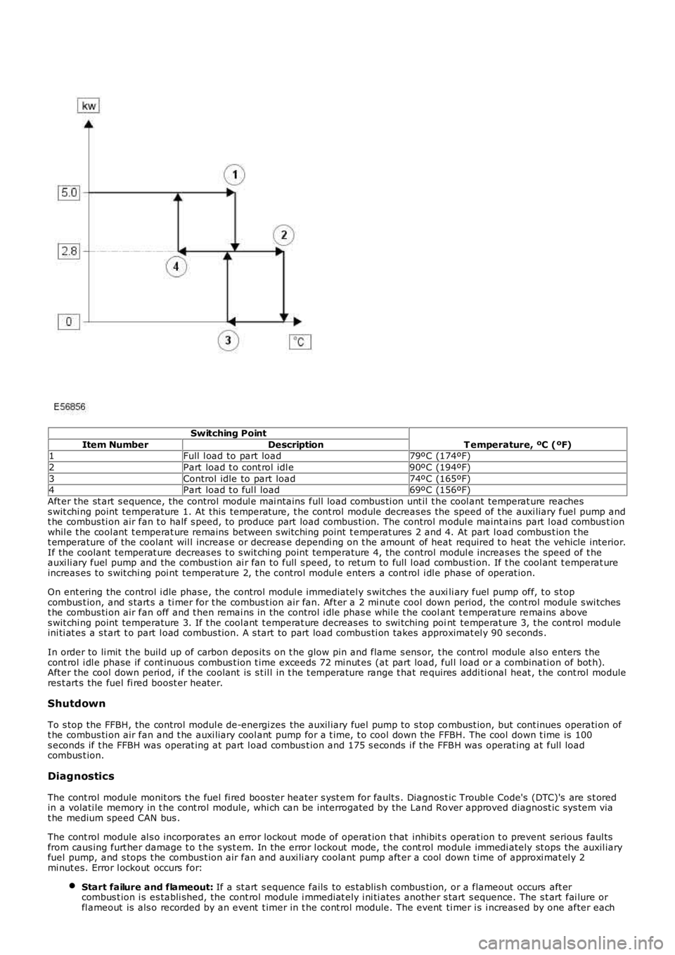
Switching Point
T emperature, ºC (ºF)Item NumberDescription1Full l oad to part load79ºC (174ºF)
2Part load t o cont rol idl e90ºC (194ºF)
3Control idle to part load74ºC (165ºF)4Part load t o ful l load69ºC (156ºF)
Aft er the st art s equence, the control modul e mai nt ains full load combus ti on unt il t he cool ant temperat ure reachess wit chi ng point temperature 1. At this temperat ure, t he cont rol module decreas es the speed of t he auxi liary fuel pump andt he combus ti on air fan t o half s peed, t o produce part load combus ti on. The control modul e maint ains part l oad combus t ionwhil e t he cool ant t emperat ure remains between s wi tching point t emperat ures 2 and 4. At part l oad combus t ion t het emperature of the coolant wil l increas e or decreas e dependi ng on t he amount of heat required t o heat the vehicle interior.If the coolant temperat ure decreas es t o s wit chi ng point temperature 4, the control modul e increas es t he speed of t heauxi li ary fuel pump and the combust ion ai r fan to full s peed, t o ret urn to full l oad combus ti on. If t he cool ant t emperat ureincreas es to s wit chi ng poi nt temperat ure 2, t he control modul e enters a cont rol i dl e phase of operat ion.
On ent ering the control i dle phas e, the control modul e immediatel y s wit ches t he auxili ary fuel pump off, t o s t opcombus t ion, and s tart s a ti mer for t he combus t ion air fan. Aft er a 2 mi nut e cool down period, the cont rol module s wi tchest he combus ti on air fan off and t hen remai ns in the control i dle phas e whil e t he coolant t emperat ure remains aboves wit chi ng point temperature 3. If t he cool ant t emperat ure decreas es to swi tching point temperat ure 3, t he cont rol moduleini ti at es a s t art t o part l oad combus t ion. A s tart to part load combus ti on takes approximat el y 90 s econds .
In order to li mit t he buil d up of carbon depos it s on t he glow pin and flame s ens or, t he cont rol module als o enters thecont rol i dl e phase if cont inuous combus t ion t ime exceeds 72 mi nut es (at part load, ful l l oad or a combinati on of bot h).Aft er the cool down period, i f the coolant is s t il l in t he t emperature range t hat requires addi ti onal heat , t he cont rol moduleres t art s the fuel fi red boost er heat er.
Shutdown
To s top the FFBH, the control modul e de-energi zes the auxil iary fuel pump to s top combust ion, but cont inues operati on oft he combus ti on air fan and t he auxi liary cool ant pump for a t ime, t o cool down the FFBH. The cool down t ime is 100s econds if t he FFBH was operat ing at part l oad combus t ion and 175 s econds i f the FFBH was operat ing at full loadcombus t ion.
Diagnostics
The cont rol module monit ors t he fuel fi red boos ter heater s yst em for fault s . Diagnost ic Troubl e Code's (DTC)'s are s t oredin a volati le memory in t he cont rol module, whi ch can be interrogated by the Land Rover approved diagnost ic sys tem viat he medium speed CAN bus .
The cont rol module al s o incorporat es an error lockout mode of operat ion t hat inhibits operat ion t o prevent serious faul tsfrom caus ing furt her damage t o t he s ys t em. In the error l ockout mode, t he cont rol module immedi ately st ops the auxil iaryfuel pump, and s tops t he combus t ion air fan and auxi li ary coolant pump aft er a cool down t ime of approxi mat el y 2mi nut es. Error l ockout occurs for:
Start failure and flameout: If a st art s equence fails to es t abl is h combus ti on, or a flameout occurs aft ercombus t ion i s es tabli shed, the cont rol module i mmediat ely i ni ti ates another s tart s equence. The s t art fai lure orfl ameout is als o recorded by an event t imer in t he cont rol module. The event ti mer is i ncreas ed by one after each
Page 1754 of 3229
s tart fail ure or flameout, and decreas ed by one if a subs equent s tart is succes s ful . If t he event t imer i ncreas es t ot hree (over any number of drive cycl es), the cont rol module ent ers t he error lockout mode.Heat exchanger casing overheat: To prot ect t he s ys t em from exces s ive t emperatures , t he cont rol module ent erst he error l ockout mode if t he heat exchanger coolant temperat ure exceeds 125 °C (257 °F).Battery voltage out of limits: Error lockout wi ll occur if bat tery vol tage fall s bel ow 10.25 or ris es above 15.5 volt s .
The error lockout mode can be cleared usi ng the Land Rover approved di agnos ti c s ys t em, or by dis connect ing the bat terypower supply for a mi nimum of 10 s econds.
Remote Operation - Vehicles from 2009MY with FFBH Remote Control
The 868.3 MHz Radi o Frequency (RF) si gnal s t ransmit ted by the remote hands et are recei ved by the DAB/FFBH ant ennalocated i n t he LH rear s i de window. The s ignal s received by t he antenna are detected by t he FFBH receiver. A 'handshake's ignal is s ent back from the recei ver t o t he hands et t o confirm a val id on or off reques t and act ivate the handset LEDaccordi ngl y. The recei ver proces s es the s i gnal it recei ved and trans mi ts the appropriate si gnal s via a dedi cat ed bus t o theFFBH cont rol module.
• NOTE: The ‘handshake’ si gnal only confi rms hands et-receiver communi cat ions were s uccess ful , and not that t he FFBH hast urned on.
W hen t he FFBH is act ivated by the remote hands et, t he FFBH cont rol module will al low t he FFBH t o operate for 30 minutesor unt il an off request is received from t he remot e hands et or CJB. During t he 30 minut e period, the FFBH may operat e i neit her full l oad combus ti on, part load combus t ion or a controll ed idle phas e of operat ion, depending on t he t emperature oft he coolant i n t he heat exchanger.
Pre-burn Thresholds
The FFBH unit wi ll only acti vat e remotely if t he fol lowing thres hold condit ions are met:
Pre-burn batt ery vol tage check: ≥11.5V (volt age at FFBH terminals )Pre-burn coolant temperat ure check: ≤15°C (int ernal FFBH measurement )Pre-burn fuel l evel check: ≥7.5 lit ers (value s t ored i n FFBH at ignit ion off)
The fuel level val ue s tored wit hin t he FFBH unit i s only updated when t he engine i s running. W hen s t art ing t he FFBH viaremot e control wit h the engi ne off, the fuel l evel value us ed in the FFBH calculat ions wi ll be t hat s t ored at t he las t key offevent . It i s t herefore poss ibl e for t he FFBH t o fai l to operat e remotel y if t he engine was s t opped wi th a low fuel level; i ft he fuel tank i s s ubs equent ly refuell ed, the FFBH s t ored fuel l evel wil l st il l read l ow i f the engine has not been s tarteds ince refuel li ng.
If the FFBH does not act ivate due to low bat tery vol tage or l ow fuel l evel, t he FFBH cont rol module transmit s a mes s age ispass ed on t he medi um and high speed CAN bus es, vi a t he CJB to the i nst rument clus ter mes s age cent er which wil l dis playone of the foll owing mes s ages at i gnit ion on:
AUXILIARY HEATER UNAVAILABLE LOW FUELAUXILIARY HEATER UNAVAILABLE LOW BATTERY .
If bot h l ow fuel and low batt ery volt age mes sages are val id, t he ins trument cl ust er mes sage center wi ll alt ernate bet weent he two mes sages .
Remote Control ‘Park Heat’ to ATC ‘Supplementary Heat’ Transitions
• NOTE: The FFBH can s ti ll be acti vat ed by t he ATC module as previ ous l y descri bed
If the FFBH has been operated remot el y (‘park heat’) and the vehicl e is st art ed whilst the FFBH i s s ti ll act ive, it willt ransi ti on int o t he ATC-control led ‘s upplement ary heat’ mode if t he ATC request s i t.
Shoul d t he ATC t hen send a mess age t o t he FFBH to turn off, the FFBH will remain active if 30 minut es has not yetelaps ed from t he ori ginal remot e cont rol ‘park heat ’ request . Once t he remai nder of 30 mi nut es has elaps ed, t he FFBH wil lt urn off.
Swit chi ng Point Temperatures
W hen remotel y s tarted t he FFBH us es a different s et of s wit chi ng poi nt temperat ures t o t he normal ‘supplement al heat’mode. Thi s is because the remot e s tart feature can s tart the FFBH wi th the engine off – t hus different t hres hol ds arerequired t o opti mis e t he heati ng of the engine coolant.
Swit chi ng Point Temperatures
Page 1755 of 3229
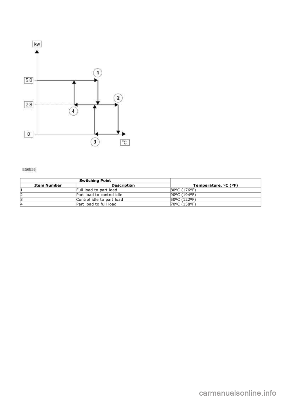
Switching Point
T emperature, ºC (ºF)Item NumberDescription1Full l oad to part load80ºC (176ºF)
2Part load t o cont rol idl e90ºC (194ºF)
3Control idle to part load50ºC (122ºF)4Part load t o ful l load70ºC (158ºF)
Page 1756 of 3229
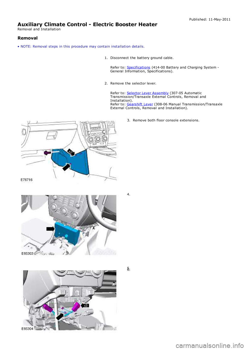
Publi s hed: 11-May-2011
Auxiliary Climate Control - Electric Booster Heater
Removal and Inst all ati on
Removal
• NOTE: Removal s t eps in t his procedure may cont ain i nst all ati on det ail s.
Di sconnect t he bat t ery ground cable.
Refer t o: Specificati ons (414-00 Bat tery and Charging Sys tem -General Informat ion, Specificati ons).
1.
Remove t he s el ect or lever.
Refer t o: Sel ect or Lever As sembl y (307-05 Aut omat icTrans mi ss ion/Transaxle Ext ernal Cont rol s , Removal andInst all at ion).Refer t o: Gears hi ft Lever (308-06 Manual Trans mis s ion/Trans axleExternal Controls , Removal and Inst all at ion).
2.
Remove both fl oor consol e ext ensi ons.3.
4.
5.6.
Page 1757 of 3229
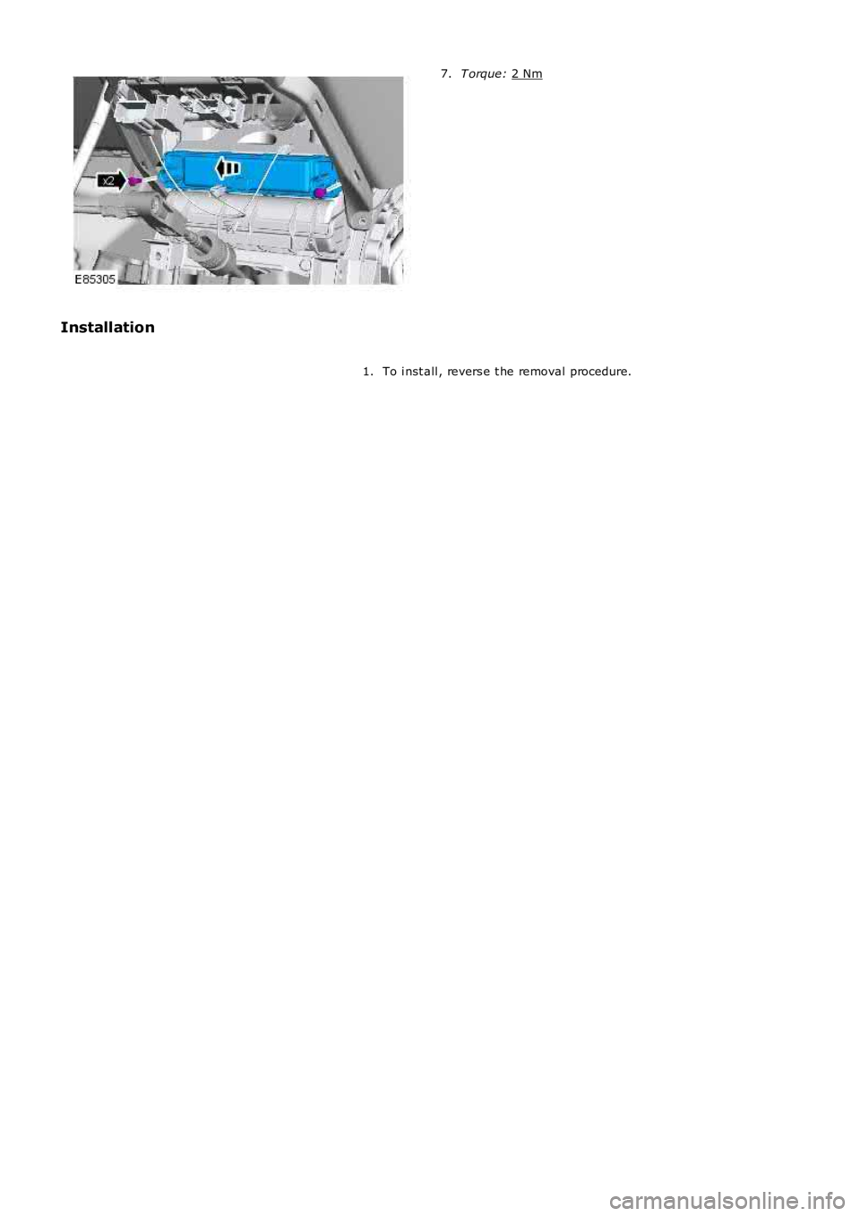
T orque:
2 Nm 7.
Installation To i nst all , revers e t he removal procedure.
1.
Page 1758 of 3229
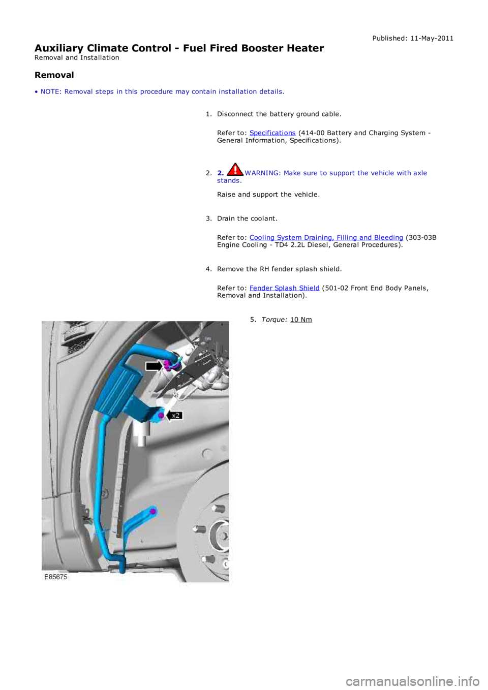
Publi s hed: 11-May-2011
Auxiliary Climate Control - Fuel Fired Booster Heater
Removal and Inst all ati on
Removal
• NOTE: Removal s t eps in t his procedure may cont ain i nst all ati on det ail s.
Di sconnect t he bat t ery ground cable.
Refer t o: Specificati ons (414-00 Bat tery and Charging Sys tem -
General Informat ion, Specificati ons).
1.
2. W ARNING: Make sure t o s upport the vehicle wit h axle
s tands .
Rais e and s upport t he vehi cl e.
2.
Drai n t he cool ant .
Refer t o: Cool ing Sys tem Drai ni ng, Fi lli ng and Bleeding (303-03B
Engine Cooli ng - TD4 2.2L Di esel , General Procedures ).
3.
Remove t he RH fender s plas h s hield.
Refer t o: Fender Spl ash Shi eld (501-02 Front End Body Panel s ,
Removal and Ins tall ati on).
4. T orque:
10 Nm 5.
Page 1759 of 3229
6.
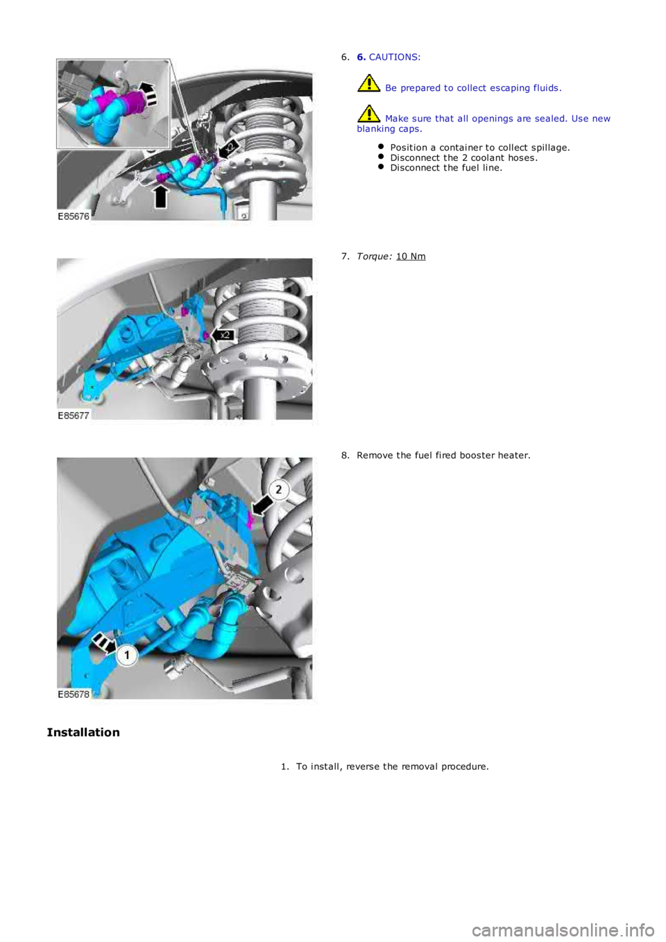
CAUTIONS: Be prepared t o collect es caping flui ds .
Make s ure that all openings are sealed. Us e new
blanking caps.
Pos it ion a contai ner t o coll ect s pil lage. Di sconnect t he 2 cool ant hos es .
Di sconnect t he fuel li ne.6.
T orque:
10 Nm 7.
Remove t he fuel fi red boos ter heater.
8.
Installation To i nst all , revers e t he removal procedure.
1.
Page 1760 of 3229
Publi s hed: 11-May-2011
Auxiliary Climate Control - Fuel Fired Booster Heater Fuel Pump
Removal and Inst all ati on
Removal
Di sconnect t he bat t ery ground cable.
Refer t o: Specificati ons (414-00 Bat tery and Charging Sys tem -
General Informat ion, Specificati ons).
1.
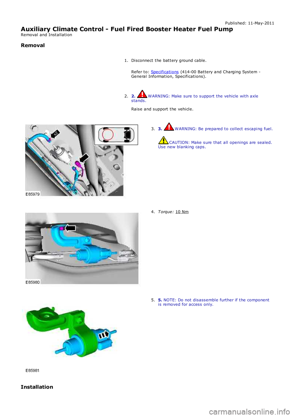
2. W ARNING: Make sure t o s upport the vehicle wit h axle
s tands .
Rais e and s upport t he vehi cl e.
2. 3. W ARNING: Be prepared t o coll ect es capi ng fuel.
CAUTION: Make s ure that all openings are sealed.
Us e new bl anki ng caps .
3. T orque:
10 Nm 4.
5.
NOTE: Do not dis ass embl e further if t he component
i s removed for acces s onl y.
5.
Installation