LAND ROVER FRELANDER 2 2006 Repair Manual
Manufacturer: LAND ROVER, Model Year: 2006, Model line: FRELANDER 2, Model: LAND ROVER FRELANDER 2 2006Pages: 3229, PDF Size: 78.5 MB
Page 1731 of 3229
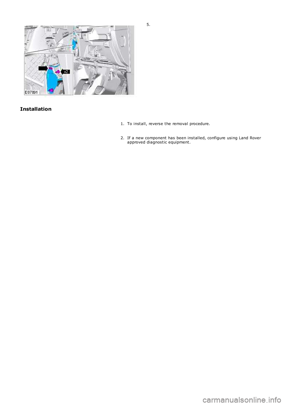
5.
Installation
To i nst all , revers e t he removal procedure.1.
If a new component has been ins t al led, configure usi ng Land Roverapproved diagnos t ic equipment .2.
Page 1732 of 3229
Publi s hed: 11-May-2011
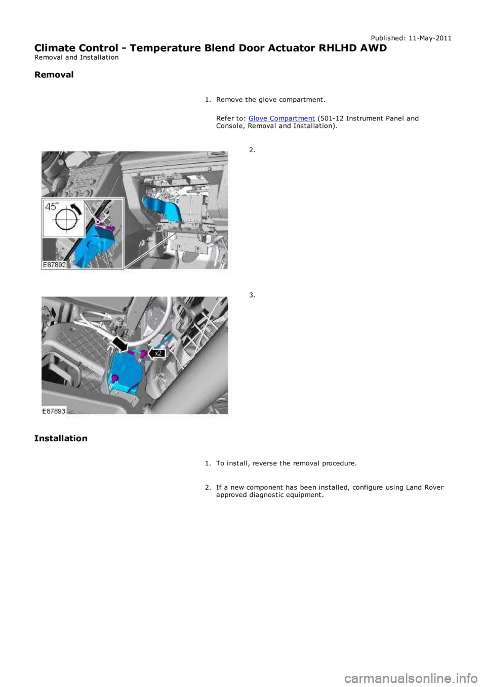
Climate Control - Temperature Blend Door Actuator RHLHD AWD
Removal and Inst all ati on
Removal
Remove t he glove compartment .
Refer t o: Glove Compart ment (501-12 Ins trument Panel and
Consol e, Removal and Ins t al lat ion).
1. 2.
3.
Installation To i nst all , revers e t he removal procedure.
1.
If a new component has been ins t al led, configure usi ng Land Rover
approved diagnos t ic equipment .
2.
Page 1733 of 3229
Publi s hed: 11-May-2011
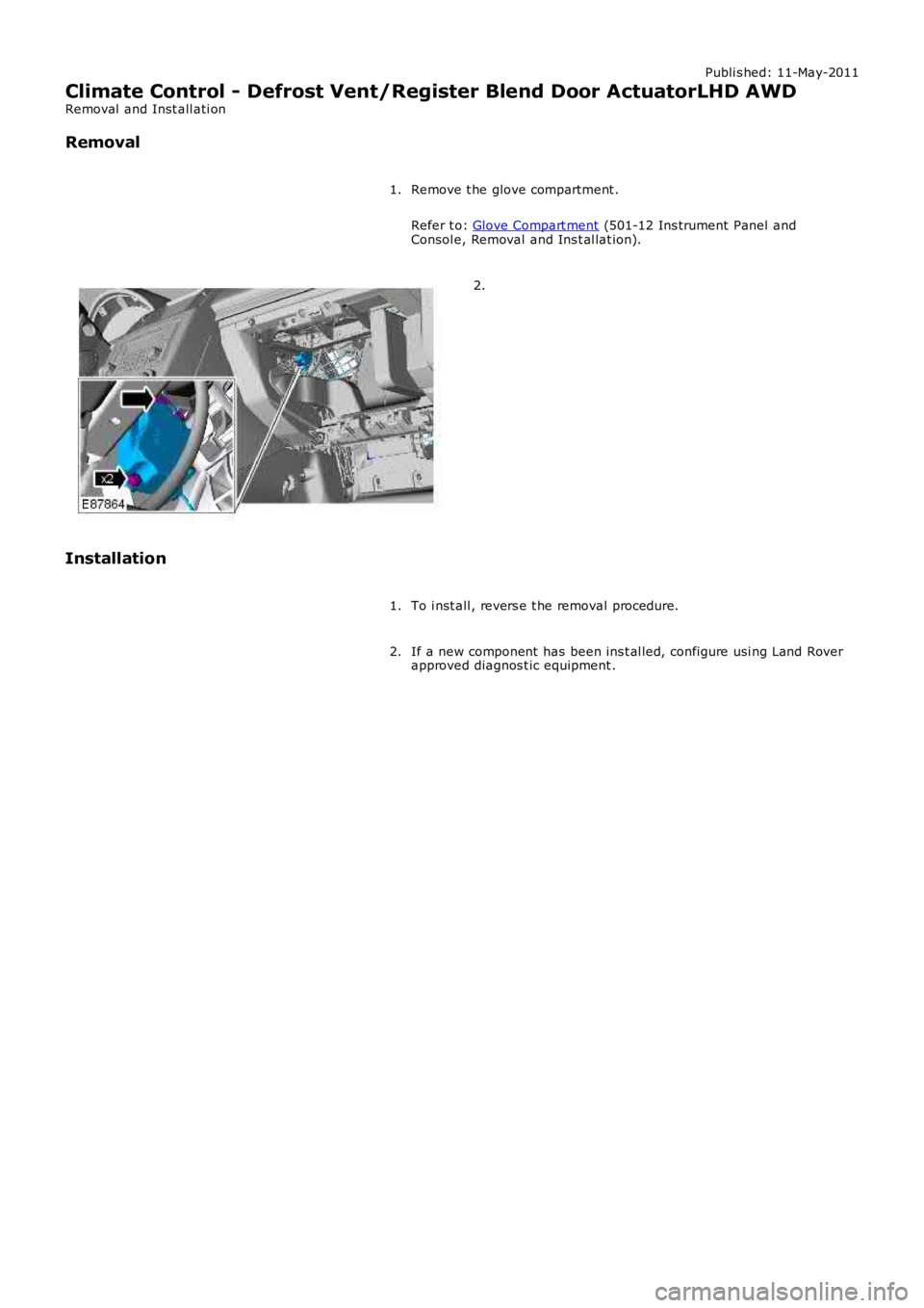
Climate Control - Defrost Vent/Register Blend Door ActuatorLHD AWD
Removal and Inst all ati on
Removal
Remove t he glove compartment .
Refer t o: Glove Compart ment (501-12 Ins trument Panel and
Consol e, Removal and Ins t al lat ion).
1. 2.
Installation To i nst all , revers e t he removal procedure.
1.
If a new component has been ins t al led, configure usi ng Land Rover
approved diagnos t ic equipment .
2.
Page 1734 of 3229
Publi s hed: 11-May-2011
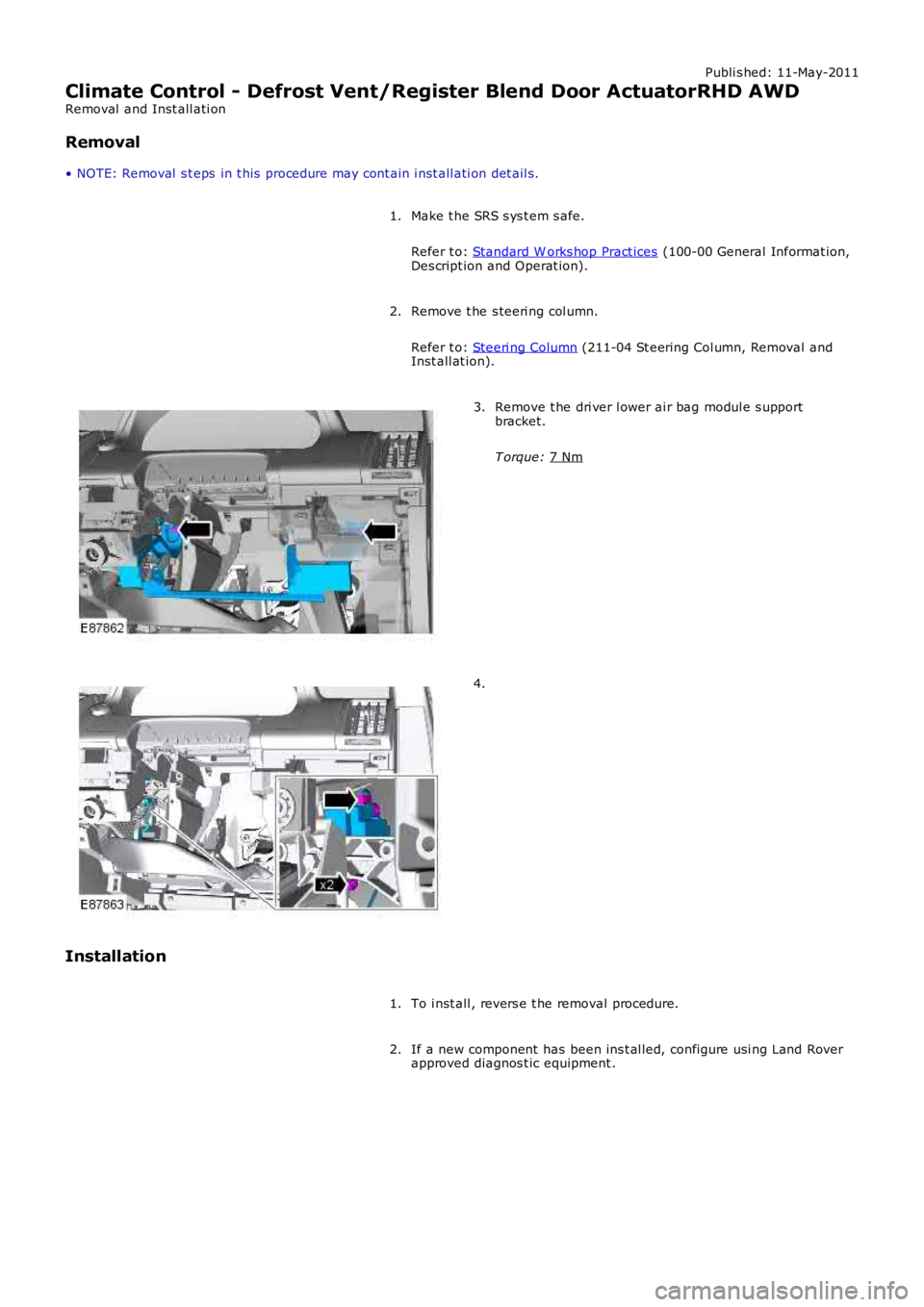
Climate Control - Defrost Vent/Register Blend Door ActuatorRHD AWD
Removal and Inst all ati on
Removal
• NOTE: Removal s t eps in t his procedure may cont ain i nst all ati on det ail s.
Make t he SRS s ys t em s afe.
Refer t o: Standard W orks hop Pract ices (100-00 General Informat ion,
Des cript ion and Operat ion).
1.
Remove t he s teeri ng col umn.
Refer t o: Steeri ng Column (211-04 St eering Col umn, Removal and
Inst all at ion).
2. Remove t he dri ver l ower ai r bag modul e s upport
bracket.
T orque: 7 Nm 3.
4.
Installation To i nst all , revers e t he removal procedure.
1.
If a new component has been ins t al led, configure usi ng Land Rover
approved diagnos t ic equipment .
2.
Page 1735 of 3229
Publi s hed: 11-May-2011
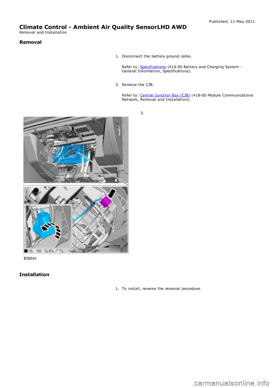
Climate Control - Ambient Air Quality SensorLHD AWD
Removal and Inst all ati on
Removal
Di sconnect t he bat t ery ground cable.
Refer t o: Specificati ons (414-00 Bat tery and Charging Sys tem -General Informat ion, Specificati ons).
1.
Remove t he CJB.
Refer t o: Cent ral Junct ion Box (CJB) (418-00 Module Communi cat ionsNet work, Removal and Ins t allat ion).
2.
3.
Installation
To i nst all , revers e t he removal procedure.1.
Page 1736 of 3229
Publi s hed: 11-May-2011
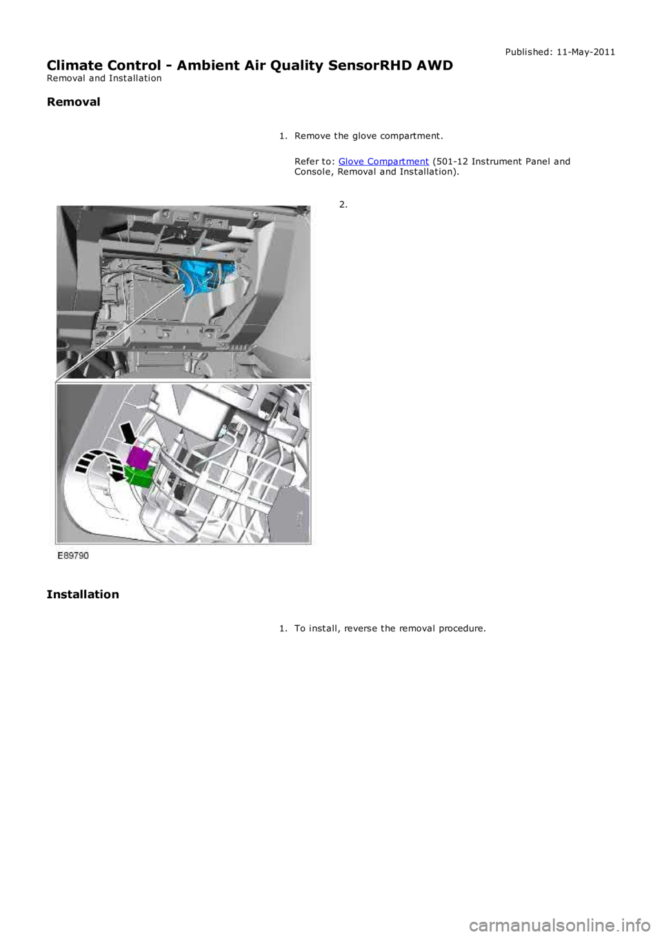
Climate Control - Ambient Air Quality SensorRHD AWD
Removal and Inst all ati on
Removal
Remove t he glove compartment .
Refer t o: Glove Compart ment (501-12 Ins trument Panel andConsol e, Removal and Ins t al lat ion).
1.
2.
Installation
To i nst all , revers e t he removal procedure.1.
Page 1737 of 3229
Publi shed: 26-Jul-2011
Auxiliary Heating - Fuel Fired Booster Heater
Diagnosi s and Tes ti ng
Overview
For informati on on t he des cri pti on and operati on of the s ys tem, refer t o s ect ion 412-02 -REFER to:
Fuel Fired Boos t er Heat er (412-02B Auxil iary Cli mate Cont rol, Des cri pt ion and Operati on),Fuel Fired Boos t er Heat er (412-02B, Des cript ion and Operat ion),Fuel Fired Boos t er Heat er (412-02B Auxil iary Cli mate Cont rol, Removal and Ins t al lat ion),Fuel Fired Boos t er Heat er Fuel Pump (412-02B Auxili ary Cl imat e Control, Removal and Ins tall ati on),Fuel Fired Boos t er Heat er Cool ant Pump (412-02B Auxil iary Cli mate Cont rol, Removal and Ins t al lat ion),Fuel Fired Boos t er Heat er Glow Pl ug And Burner As sembl y (412-02B Auxi liary Cli mate Cont rol , Removal andIns tal lat ion).Auxi li ary Heat ing i n the works hop manual .
Inspection and Verification
1. Verify t he cus t omer concern.1.
2. Vis ually ins pect for obvious mechani cal or electrical fault s .2.
Visual inspectionMechanicalElectrical
Fuel fired heater as sembl y- Combus ti on air fan- Coolant inl et /out let- Heat exchanger- Temperat ure s ens or- Exhaus t- Fuel inlet- Ai r inlet- EvaporatorAuxili ary fuel pump and li nesAuxili ary coolant pump
Fus esHarness esEl ect ri cal connector(s )Cont roll er area network (CAN) ci rcuit sCont rol module(s)
3. If an obvious cause for an obs erved or report ed concern is found, correct t he caus e (if pos s ible) beforeproceeding t o t he next s t ep3.
4. Us e the approved di agnos ti c s ys t em or a s can t ool t o ret rieve any diagnos t ic t rouble codes (DTCs ) before movingont o t he sympt om chart or DTC i ndex.4.
CAUTION: Di agnos is by s ubs ti tut ion from a donor vehicle is NO T acceptabl e. Subs ti tut ion of cont rol modules doesnot guarant ee confirmat ion of a faul t, and may als o caus e addit ional fault s i n t he vehi cl e being t est ed and/or t he donorvehi cl e.
• NOTE: If the control modul e or a component i s s us pect and the vehicle remains under manufacturer warrant y, refer t o theW arranty Pol icy and Procedures manual (s ect ion B1.2), or determine i f any pri or approval programme is in operat ion, pri ort o the ins tall ati on of a new module/component.
• NOTE: Generic scan t ool s may not read the codes li st ed, or may read only 5-digi t codes . Match t he 5 digi ts from t he s cant ool t o t he fi rs t 5 di gi ts of the 7-digit code li s ted t o i dent ify the fault (the last 2 digi ts gi ve ext ra informati on read by themanufacturer-approved di agnos ti c s ys t em).
• NOTE: Check and recti fy bas ic faul ts before beginni ng diagnos t ic rout ines i nvol vi ng pinpoint t es t s.
• NOTE: Ins pect connect ors for s igns of water ingres s , and pins for damage and/or corros ion.
• NOTE: If DTCs are recorded and, aft er performi ng the pi npoi nt tes ts , a fault is not present , an int ermi tt ent concern maybe t he caus e. Always check for loose connect ions and corroded terminals .
The t abl e below l is t s all Diagnos ti c Trouble Codes (DTCs ) t hat could be logged in the Fuel Fi red Boos ter Heater Module, foraddi ti onal Di agnos is and Tes ti ng informat ion refer t o t he relevant Diagnosi s and Test ing Secti on
DTC index
For a compl ete lis t of all Di agnos ti c Trouble Codes (DTCs) t hat could be logged on this vehicle, pleas e refer to Sect ion100-00. REFER t o: Diagnost ic Troubl e Code (DTC) Index - DTC: Auxi li ary Heater Control Modul e (AHCM) (100-00 GeneralInformat ion, Des cript ion and Operat ion).
Page 1738 of 3229
Publi s hed: 11-May-2011
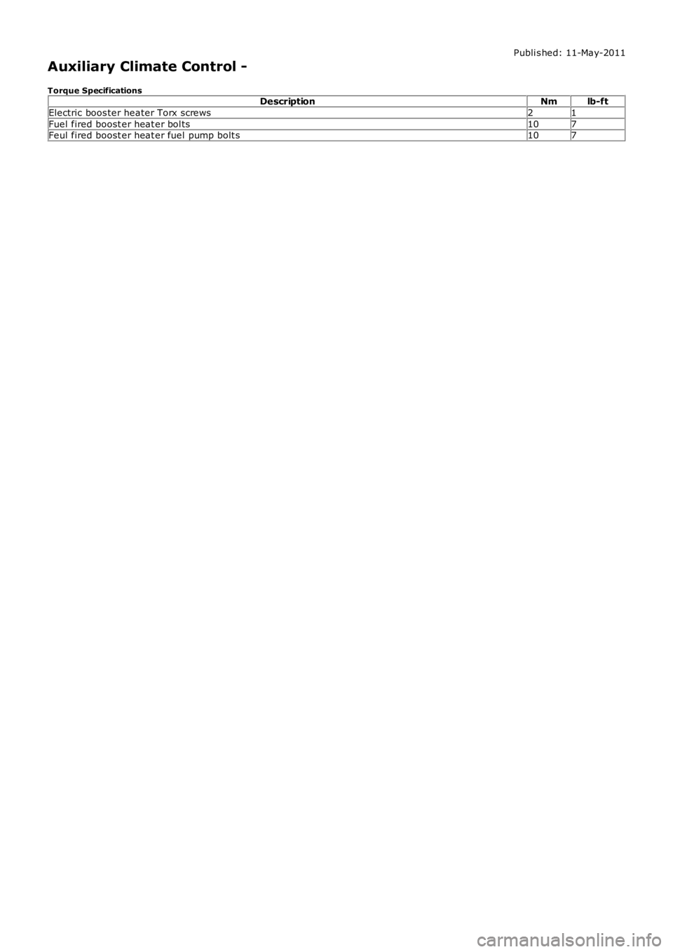
Auxiliary Climate Control -
Torque SpecificationsDescriptionNmlb-ft
Electric boos ter heater Torx screws21
Fuel fired boost er heat er bol ts107Feul fired boost er heat er fuel pump bolt s107
Page 1739 of 3229
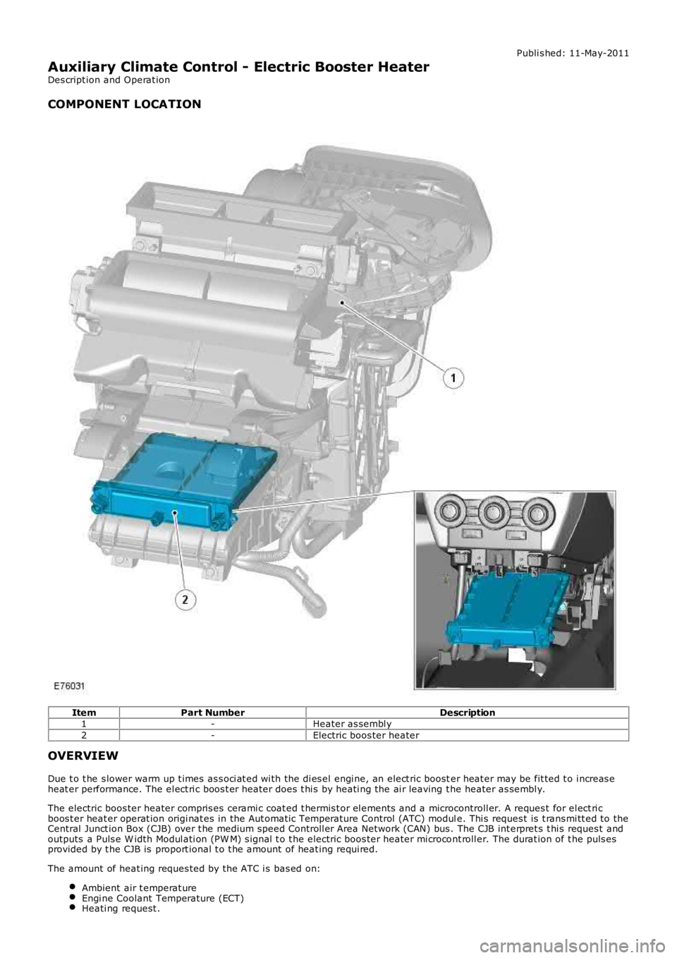
Publi s hed: 11-May-2011
Auxiliary Climate Control - Electric Booster Heater
Des cript ion and Operat ion
COMPONENT LOCATION
ItemPart NumberDescription1-Heater as sembl y
2-Electric boos ter heater
OVERVIEW
Due t o t he s lower warm up t imes as s oci at ed wi th the di es el engi ne, an elect ric booster heat er may be fit ted t o i ncreas eheat er performance. The el ect ri c boos t er heater does t hi s by heati ng the ai r leaving t he heater as sembl y.
The electric boos ter heater compris es cerami c coat ed t hermis t or el ements and a microcontroll er. A reques t for el ect ri cboos t er heat er operat ion origi nat es in the Aut omati c Temperature Control (ATC) module. Thi s reques t is t rans mi tt ed to theCentral Junct ion Box (CJB) over t he medium speed Controll er Area Network (CAN) bus . The CJB int erpret s t hi s reques t andoutputs a Puls e W idth Modul ati on (PW M) s ignal t o t he electric boos ter heater mi crocont roll er. The durat ion of t he puls esprovided by t he CJB is proport ional t o t he amount of heat ing requi red.
The amount of heat ing reques ted by the ATC i s bas ed on:
Ambient air t emperat ureEngi ne Coolant Temperature (ECT)Heati ng request .
Page 1740 of 3229

• NOTE: There i s als o a mini mum bl ower motor s peed required el ect ri c boost er heat er operat ion.
The electric boos ter heater is limit ed to 1.25 kW . If electrical load management is i n force, el ect ri c boos t er heaterperformance wil l be reduced.
• NOTE: Vehicles fit ted wit h an electric boos ter heater and heated wi nds hiel d wi ll als o be fit ted wit h an uprat ed 180 ampgenerator.For addit ional informat ion, refer t o: Generator - TD4 2.2L Dies el (414-02 Generat or and Regulat or, Des cript ion andOperat ion).