LAND ROVER FRELANDER 2 2006 Repair Manual
Manufacturer: LAND ROVER, Model Year: 2006, Model line: FRELANDER 2, Model: LAND ROVER FRELANDER 2 2006Pages: 3229, PDF Size: 78.5 MB
Page 2791 of 3229
71
Steering wheel
R
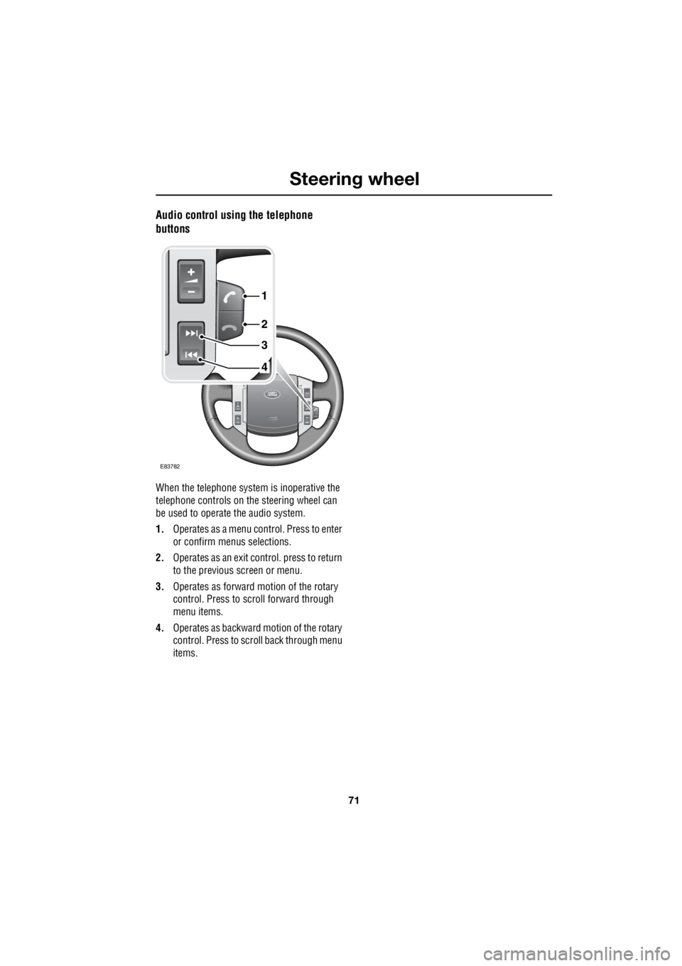
Audio control using the telephone
buttons
When the telephone syst em is inoperative the
telephone controls on th e steering wheel can
be used to operate the audio system.
1. Operates as a menu control. Press to enter
or confirm menus selections.
2. Operates as an exit control. press to return
to the previous screen or menu.
3. Operates as forward motion of the rotary
control. Press to scroll forward through
menu items.
4. Operates as backward motion of the rotary
control. Press to scroll back through menu
items.
4
3
2
1
E83782
Page 2792 of 3229
Lighting
72
L
LightingLIGHTING CONTROL
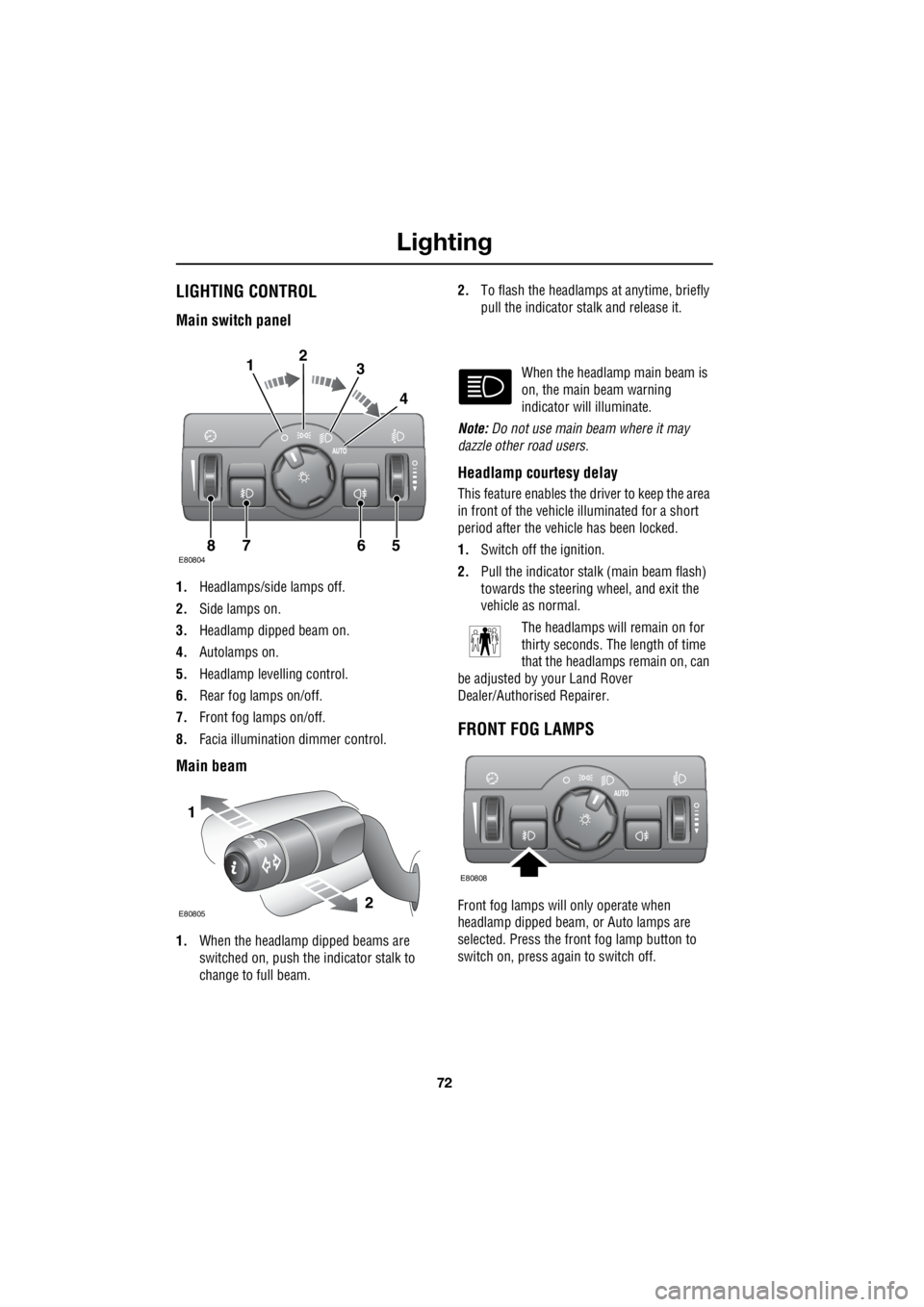
Main switch panel
1. Headlamps/side lamps off.
2. Side lamps on.
3. Headlamp dipped beam on.
4. Autolamps on.
5. Headlamp levelling control.
6. Rear fog lamps on/off.
7. Front fog lamps on/off.
8. Facia illumination dimmer control.
Main beam
1.When the headlamp dipped beams are
switched on, push the indicator stalk to
change to full beam. 2.
To flash the headlamps at anytime, briefly
pull the indicator stalk and release it.
When the headlamp main beam is
on, the main beam warning
indicator will illuminate.
Note: Do not use main beam where it may
dazzle other road users.
Headlamp courtesy delay
This feature enables the driver to keep the area
in front of the vehicle illuminated for a short
period after the vehicle has been locked.
1. Switch off the ignition.
2. Pull the indicator stalk (main beam flash)
towards the steering wheel, and exit the
vehicle as normal.
The headlamps will remain on for
thirty seconds. The length of time
that the headlamps remain on, can
be adjusted by your Land Rover
Dealer/Authorised Repairer.
FRONT FOG LAMPS
Front fog lamps will only operate when
headlamp dipped beam, or Auto lamps are
selected. Press the front fog lamp button to
switch on, press again to switch off.
E808047865
123
4
1
2E80805
E80808
Page 2793 of 3229
73
Lighting
R
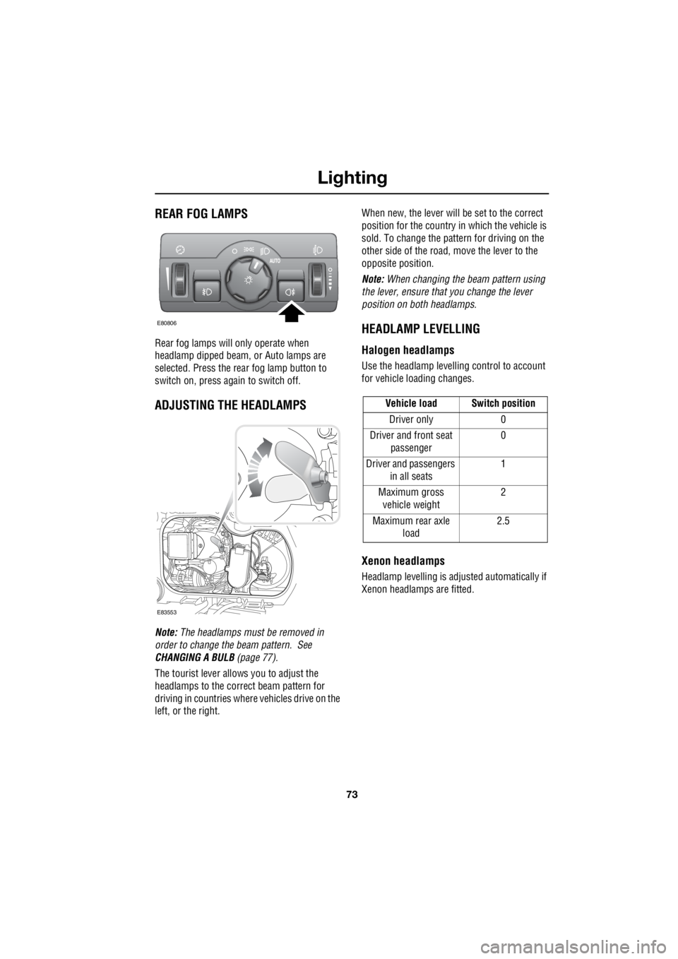
REAR FOG LAMPS
Rear fog lamps will only operate when
headlamp dipped beam, or Auto lamps are
selected. Press the rear fog lamp button to
switch on, press again to switch off.
ADJUSTING THE HEADLAMPS
Note: The headlamps must be removed in
order to change the beam pattern. See
CHANGING A BULB (page 77).
The tourist lever allows you to adjust the
headlamps to the correct beam pattern for
driving in countries where vehicles drive on the
left, or the right. When new, the lever will be set to the correct
position for the country in which the vehicle is
sold. To change the pattern for driving on the
other side of the road, move the lever to the
opposite position.
Note: When changing the beam pattern using
the lever, ensure that you change the lever
position on both headlamps.
HEADLAMP LEVELLING
Halogen headlamps
Use the headlamp levell ing control to account
for vehicle loading changes.
Xenon headlamps
Headlamp levelling is adju sted automatically if
Xenon headlamps are fitted.
E80806
E83553
Vehicle load Switch position
Driver only 0
Driver and front seat passenger 0
Driver and passengers in all seats 1
Maximum gross vehicle weight 2
Maximum rear axle load 2.5
Page 2794 of 3229
Lighting
74
L
HAZARD WARNING FLASHERS
Press the switch to turn the hazard warning
lamps on. When the hazard warning lamps are
operating, the indicator warning lamps will
flash in time with the hazard warning lamps.
Note: Hazard warning lamps can be used when
the ignition is on or off.
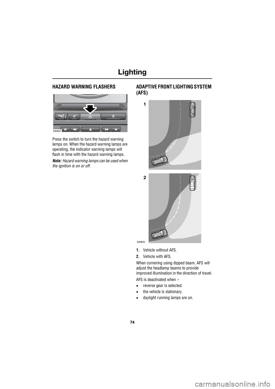
ADAPTIVE FRONT LIGHTING SYSTEM
(AFS)
1. Vehicle without AFS.
2. Vehicle with AFS.
When cornering using dipped beam, AFS will
adjust the headlamp beams to provide
improved illumination in the direction of travel.
AFS is deactivated when :-
• reverse gear is selected.
• the vehicle is stationary.
• daylight running lamps are on.
E80807
1
2
E80823
Page 2795 of 3229
75
Lighting
R
If a system fault is detected the
headlamps will attempt to move to
the central positio n, and remain
stationary. The AFS wa rning indicator will
illuminate to indicate th at a fault is present.
If the warning indicato r illuminates, contact
your Land Rover Dealer/A uthorised Repairer as
soon as possible.
DIRECTION INDICATORS
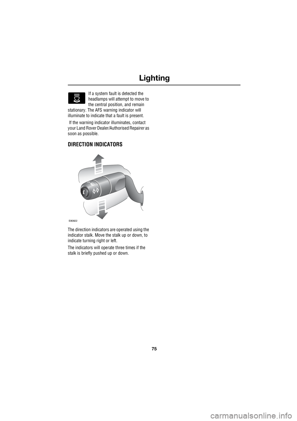
The direction indicators are operated using the
indicator stalk. Move the stalk up or down, to
indicate turning right or left.
The indicators will operate three times if the
stalk is briefly pushed up or down.
E80822
Page 2796 of 3229
Lighting
76
L
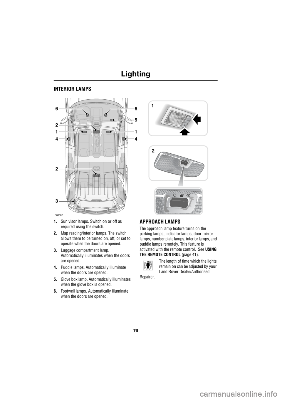
INTERIOR LAMPS
1. Sun visor lamps. Sw itch on or off as
required using the switch.
2. Map reading/interior lamps. The switch
allows them to be turn ed on, off, or set to
operate when the doors are opened.
3. Luggage compartment lamp.
Automatically illuminates when the doors
are opened.
4. Puddle lamps. Automatically illuminate
when the doors are opened.
5. Glove box lamp. Auto matically illuminates
when the glove box is opened.
6. Footwell lamps. Auto matically illuminate
when the doors are opened.APPROACH LAMPS
The approach lamp feature turns on the
parking lamps, indica tor lamps, door mirror
lamps, number plate lamps, interior lamps, and
puddle lamps remotely . This feature is
activated with the remote control. See USING
THE REMOTE CONTROL (page 41).
The length of time which the lights
remain on can be adjusted by your
Land Rover Dealer/Authorised
Repairer.
3
2
4
1
2
6
4
1
5
61
2
E83602
Page 2797 of 3229
77
Lighting
R
CHANGING A BULB
General information
Note: In certain territori es it is a legal
requirement to carry spare bulbs. A
replacement bulb kit is available as an
approved accessory from your Land Rover
Dealer/Authorised Repairer.
Halogen bulbs
Halogen bulbs are used for main beam, dipped
beam, and front fog lamps. Take care not to
touch the glass part of the bulb with your
fingers; always use a cl oth to handle the bulb.
If necessary use methylated spirits to remove
finger prints. Xenon lamps
Seek advice a bout the correct
disposal of Bi-X enon lamp units
from a Land Rover
Dealer/Authorised Repairer, or your local
authority.
CAUTION
Alway replace bulbs with the correct
type and specification. If you are in any
doubt contact your Land Rover
Dealer/Authorised Repairer for advice.
WARNINGS
Replacement or maintenance of
Xenon lamps should only be carried
out by suitably qualified personnel.
High voltage is requi red to ignite the
gas and metal vapour which are used
to power Xenon lamps. Contact with
this voltage can cause serious injuries.
Bi-Xenon lamp units operate at a very
high temperature. Ensure that the
lamp units have cooled before
attempting to touch them.
Xenon lamp units contain Mercury
which is highly to xic, and can be
extremely harmful.
Page 2798 of 3229
Lighting
78
L
Removing the headlamp unit
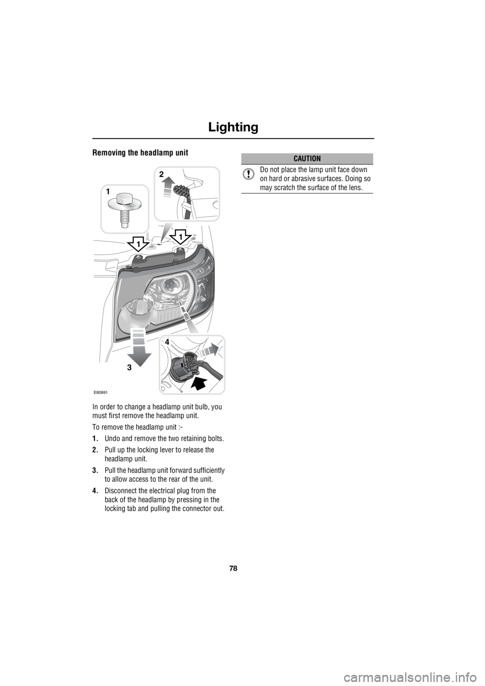
In order to change a headlamp unit bulb, you
must first remove the headlamp unit.
To remove the headlamp unit :-
1. Undo and remove the two retaining bolts.
2. Pull up the locking lever to release the
headlamp unit.
3. Pull the headlamp unit forward sufficiently
to allow access to the rear of the unit.
4. Disconnect the electrical plug from the
back of the headlamp by pressing in the
locking tab and pulling the connector out.
1
3
4
1
E80991
2
1
CAUTION
Do not place the la mp unit face down
on hard or abrasive surfaces. Doing so
may scratch the surface of the lens.
Page 2799 of 3229
79
Lighting
R
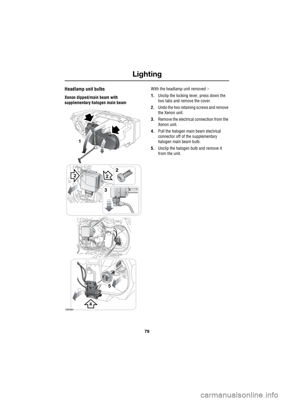
Headlamp unit bulbs
Xenon dipped/main beam with
supplementary halogen main beam With the headlamp unit removed :-
1. Unclip the locking lever, press down the
two tabs and remove the cover.
2. Undo the two retaining screws and remove
the Xenon unit.
3. Remove the electrical connection from the
Xenon unit.
4. Pull the halogen main beam electrical
connector off of the supplementary
halogen main beam bulb.
5. Unclip the halogen bulb and remove it
from the unit.
2
4
2
5
3
E80994
1
2
Page 2800 of 3229
Lighting
80
L
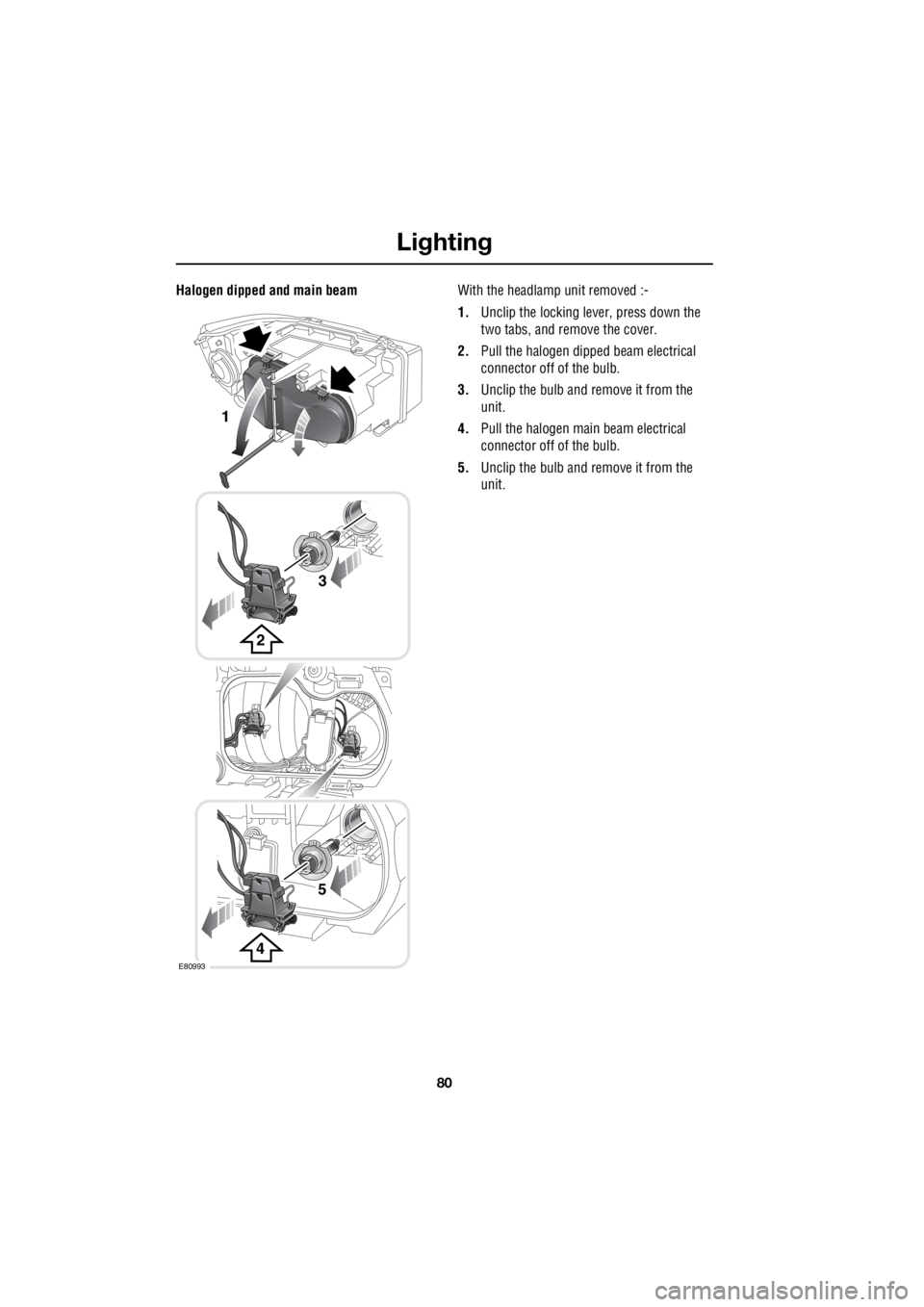
Halogen dipped and main beam With the headlamp unit removed :-
1. Unclip the locking lever, press down the
two tabs, and remove the cover.
2. Pull the halogen dipped beam electrical
connector off of the bulb.
3. Unclip the bulb and remove it from the
unit.
4. Pull the halogen main beam electrical
connector off of the bulb.
5. Unclip the bulb and remove it from the
unit.
2
3
1
4
5
E80993