LEXUS LS430 2003 Factory Repair Manual
Manufacturer: LEXUS, Model Year: 2003,
Model line: LS430,
Model: LEXUS LS430 2003
Pages: 4500, PDF Size: 87.45 MB
LEXUS LS430 2003 Factory Repair Manual
LS430 2003
LEXUS
LEXUS
https://www.carmanualsonline.info/img/36/57050/w960_57050-0.png
LEXUS LS430 2003 Factory Repair Manual
Trending: mirror, check oil, B2402, wiring diagram, Rear control Arm, air suspension, seat adjustment
Page 1001 of 4500
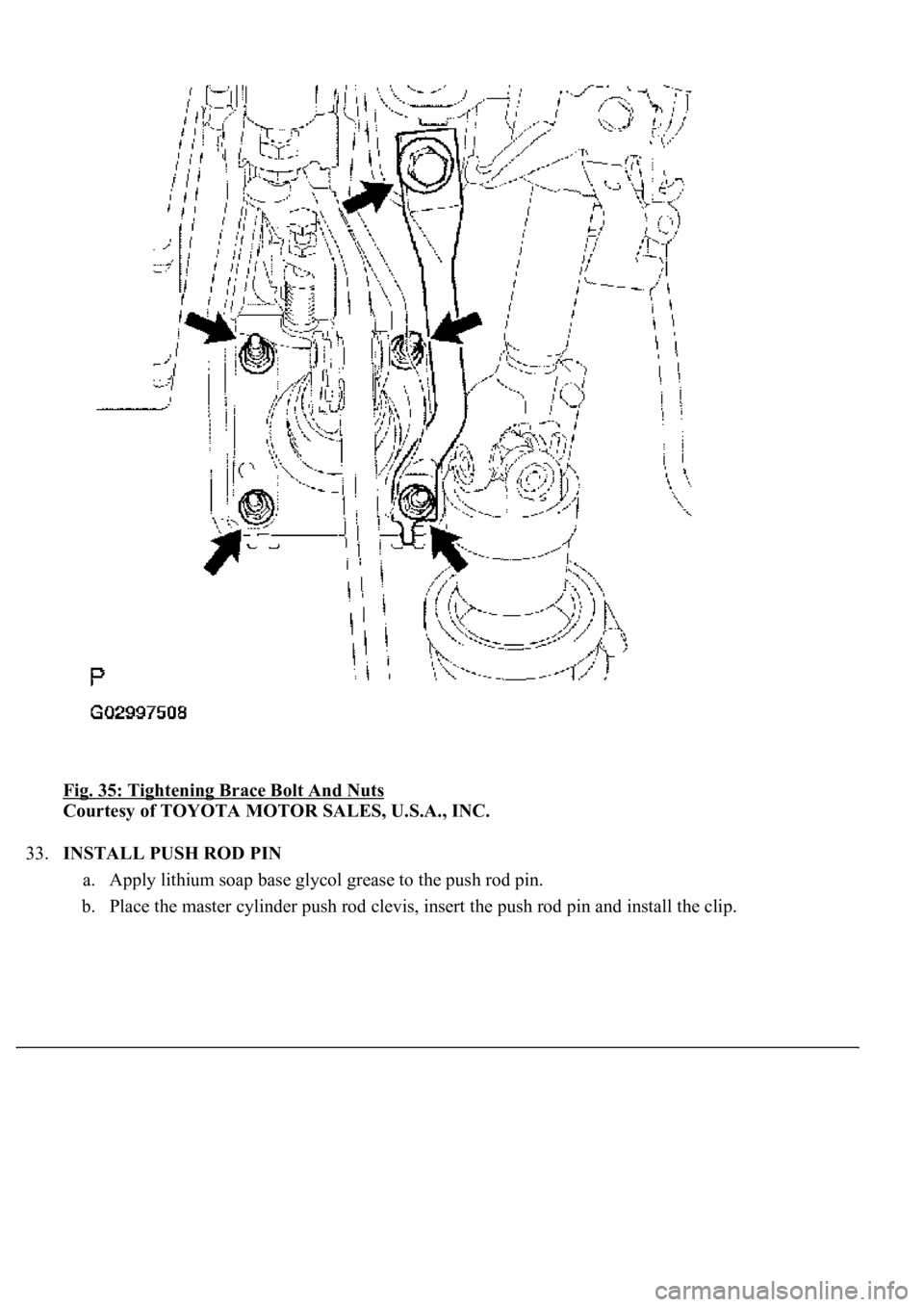
Fig. 35: Tightening Brace Bolt And Nuts
Courtesy of TOYOTA MOTOR SALES, U.S.A., INC.
33.INSTALL PUSH ROD PIN
a. Apply lithium soap base glycol grease to the push rod pin.
b. Place the master cylinder push rod clevis, insert the push rod pin and install the clip.
Page 1002 of 4500
Fig. 36: Inserting Push Rod Pin
Courtesy of TOYOTA MOTOR SALES, U.S.A., INC.
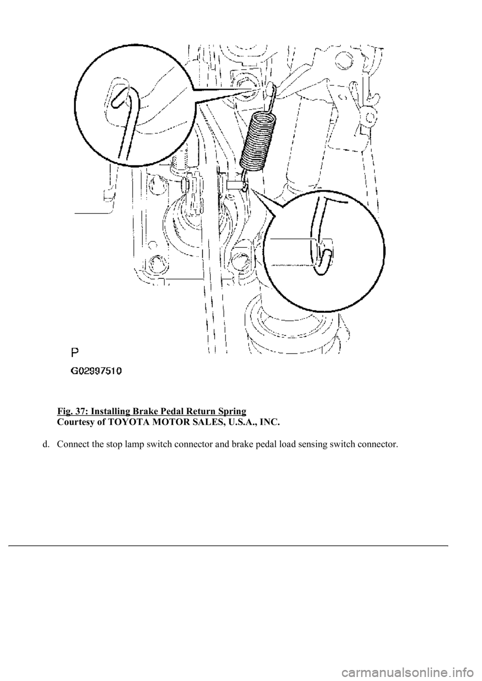
c. Install the brake pedal return sprin
g.
Page 1003 of 4500
Fig. 37: Installing Brake Pedal Return Spring
Courtesy of TOYOTA MOTOR SALES, U.S.A., INC.
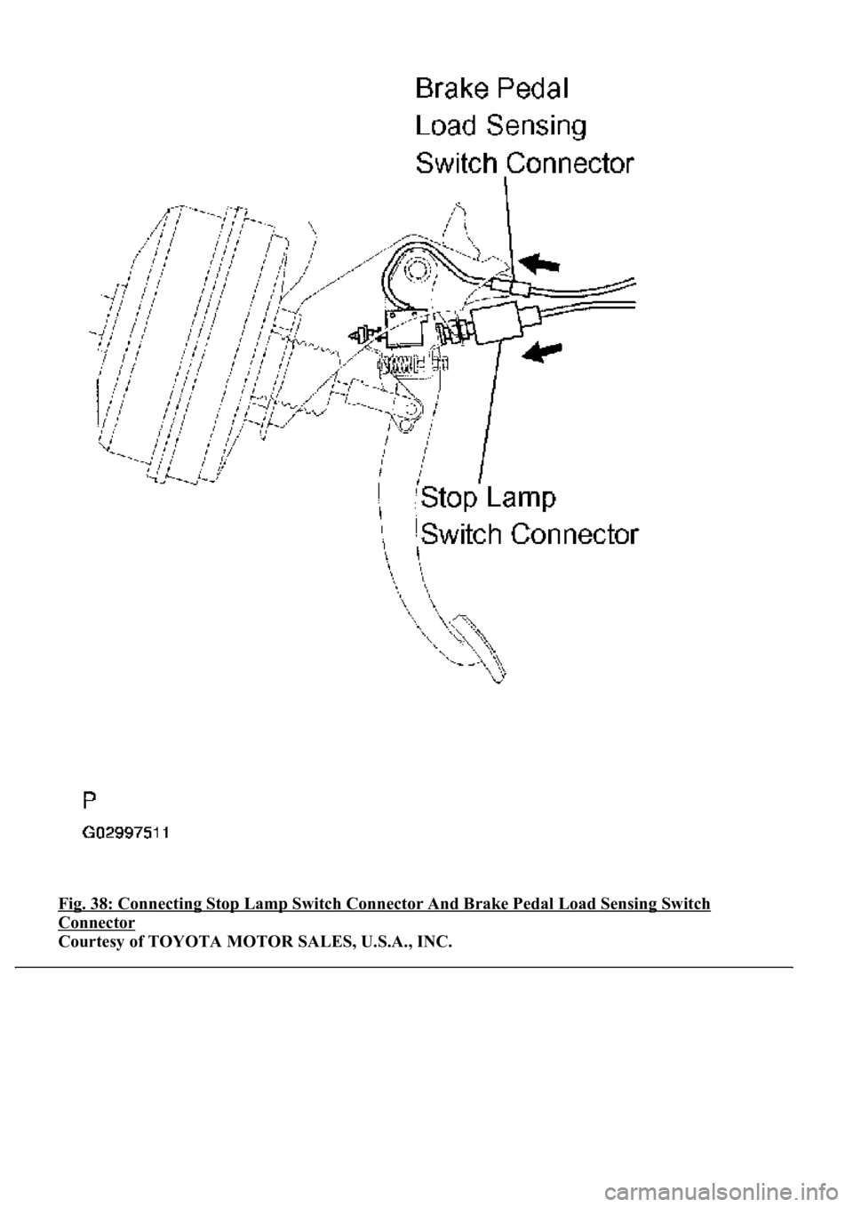
d. Connect the stop lamp switch connector and brake pedal load sensing switch connector.
Page 1004 of 4500
Fig. 38: Connecting Stop Lamp Switch Connector And Brake Pedal Load Sensing Switch
Connector
Courtesy of TOYOTA MOTOR SALES, U.S.A., INC.
Page 1005 of 4500

34.CHECK AND ADJUST BRAKE PEDAL HEIGHT (SEE ON-VEHICLE INSPECTION )
35.CHECK PEDAL FREE PLAY (SEE ON
-VEHICLE INSPECTION )
36.CHECK PEDAL RESERVE DISTANCE (SEE ON
-VEHICLE INSPECTION )
37.INSTALL COMBINATION METER ASSY (SEE OVERHAUL
)
38.INSTALL INSTRUMENT CLUSTER FINISH PANEL (SEE REPLACEMENT
)
39.INSTALL INSTRUMENT PANEL UNDER COVER SUB-ASSY NO.2 (SEE REPLACEMENT
)
40.INSTALL INSTRUMENT PANEL AIR BAG ASSY LOWER NO.1 (SEE REPLACEMENT
)
41.INSTALL INSTRUMENT PANEL SAFETY PAD SUB-ASSY NO.1 (SEE REPLACEMENT
)
42.INSTALL OUTER MIRROR SWITCH ASSY
43.INSTALL COIN BOX ASSY
44.INSTALL INSTRUMENT PANEL UNDER COVER SUB-ASSY NO.1 (SEE REPLACEMENT
)
45.INSTALL INSTRUMENT CLUSTER FINISH PANEL CENTER LOWER
46.INSTALL INSTRUMENT CLUSTER FINISH PANEL END
47.INSTALL TURN SIGNAL SWITCH ASSY (SEE REPLACEMENT
)
48.INSTALL SPIRAL CABLE SUB-ASSY (SEE REPLACEMENT
)
49.INSTALL STEERING COLUMN COVER (SEE OVERHAUL
)
50.INSTALL STEERING WHEEL ASSY (SEE OVERHAUL
)
<00360036003700030013001c001c001800130010001800130013001400160003000b0013001c001c00180014001000130018001300140013000f00030013001c001c00180015001000130018001300140013000f00030013001c001c001800160010001300
18001300150013000f00030013001c001c0018001700100013[5021)
51.INSTALL HORN BUTTON ASSY (SEE OVERHAUL
)
52.INSTALL STEERING WHEEL COVER LOWER NO.2
53.INSTALL SWITCH & VOLUME CASE
54.CONNECT BATTERY NEGATIVE TERMINAL
55.INSPECT SRS WARNING LIGHT (SEE DIAGNOSIS SYSTEM
)
56.PERFORM INITIALIZATION (SEE PRECAUTION
)
OVERHAUL
1.REMOVE ENGINE ROOM SIDE COVER
2.SEPARATE ENGINE ROOM NO.3 R/B
a. Remove the bolt and separate the engine room No.3 R/B.
3.DRAIN BRAKE FLUID
a. Draw out fluid with syringe.
4.REMOVE BRAKE MASTER CYLINDER SUB-ASSY
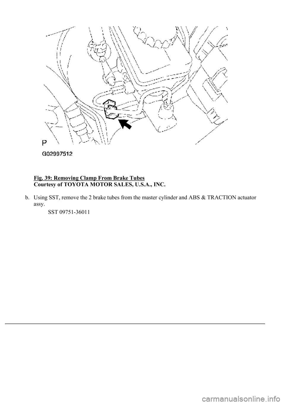
a. Remove the clamp from the 2 brake tubes.
Page 1006 of 4500
Fig. 39: Removing Clamp From Brake Tubes
Courtesy of TOYOTA MOTOR SALES, U.S.A., INC.
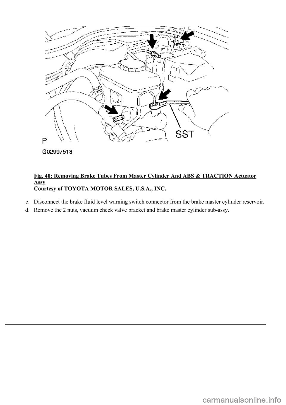
b. Using SST, remove the 2 brake tubes from the master cylinder and ABS & TRACTION actuator
assy.
SST 09751-36011
Page 1007 of 4500
Fig. 40: Removing Brake Tubes From Master Cylinder And ABS & TRACTION Actuator
Assy
Courtesy of TOYOTA MOTOR SALES, U.S.A., INC.
c. Disconnect the brake fluid level warning switch connector from the brake master cylinder reservoir.
d. Remove the 2 nuts, vacuum check valve bracket and brake master c
ylinder sub-assy.
Page 1008 of 4500
Fig. 41: Removing Brake Master Cylinder Sub-Assy Nuts
Courtesy of TOYOTA MOTOR SALES, U.S.A., INC.
5.REMOVE BRAKE MASTER CYLINDER RESERVOIR SUB-ASSY
a. Remove the brake master cylinder reservoir filler cap and master cylinder reservoir strainer.
HINT:
Using 2 fingers, pull up and turn the master cylinder reservoir strainer counterclockwise to remove.
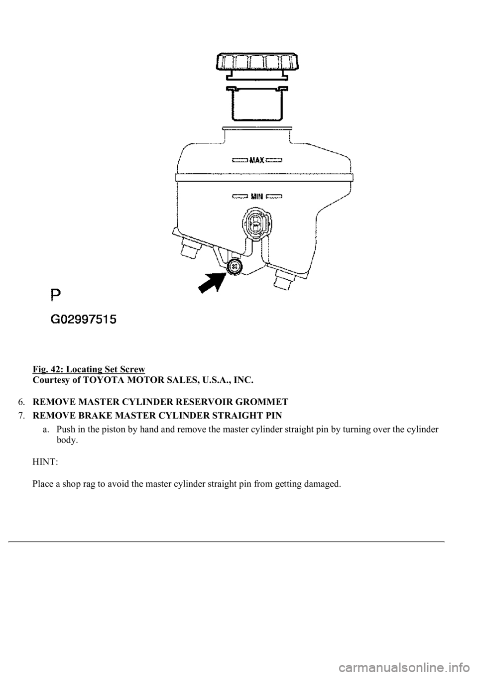
b. Remove the set screw and pull out the reservoir.
Page 1009 of 4500
Fig. 42: Locating Set Screw
Courtesy of TOYOTA MOTOR SALES, U.S.A., INC.
6.REMOVE MASTER CYLINDER RESERVOIR GROMMET
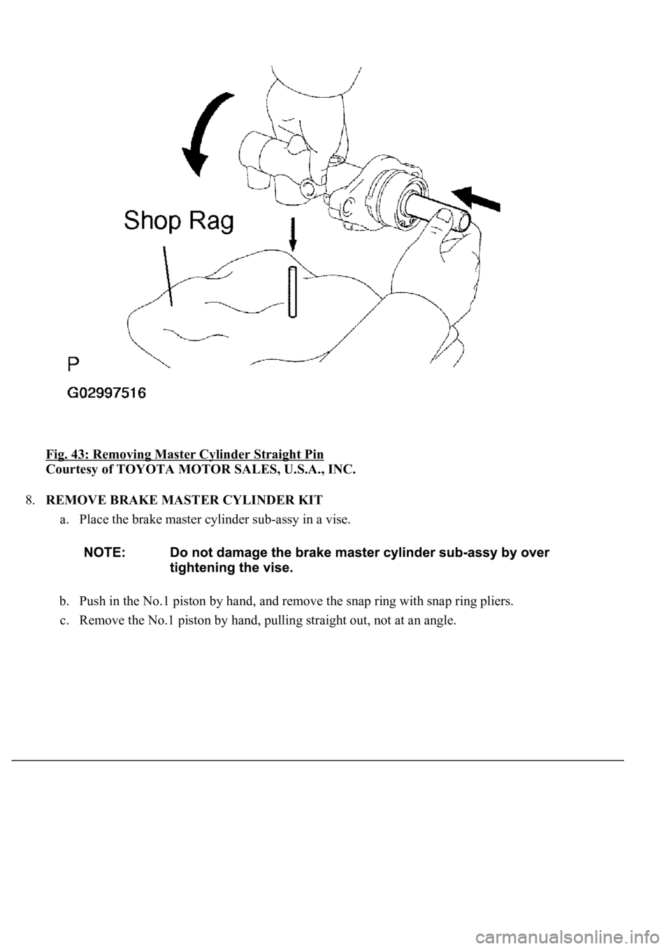
7.REMOVE BRAKE MASTER CYLINDER STRAIGHT PIN
a. Push in the piston by hand and remove the master cylinder straight pin by turning over the cylinder
body.
HINT:
Place a shop ra
g to avoid the master cylinder straight pin from getting damaged.
Page 1010 of 4500
Fig. 43: Removing Master Cylinder Straight Pin
Courtesy of TOYOTA MOTOR SALES, U.S.A., INC.
8.REMOVE BRAKE MASTER CYLINDER KIT
a. Place the brake master cylinder sub-assy in a vise.
b. Push in the No.1 piston by hand, and remove the snap ring with snap ring pliers.
c. Remove the No.1 piston b
y hand, pulling straight out, not at an angle.
Trending: headlamp, parking brake, airbag, content, ABS, oil, warning
