LEXUS LS430 2003 Factory Repair Manual
Manufacturer: LEXUS, Model Year: 2003,
Model line: LS430,
Model: LEXUS LS430 2003
Pages: 4500, PDF Size: 87.45 MB
LEXUS LS430 2003 Factory Repair Manual
LS430 2003
LEXUS
LEXUS
https://www.carmanualsonline.info/img/36/57050/w960_57050-0.png
LEXUS LS430 2003 Factory Repair Manual
Trending: coolant temperature, cruise control, manual transmission, steering wheel adjustment, service schedule, differential, radiator
Page 1381 of 4500
NG: REPAIR OR REPLACE GATEWAY ECU SUB BUS LINE OR CONNECTOR (CAN-H,
CAN-L)
18.CONNECT CONNECTOR
a. Reconnect the ECM sub bus line connector (J40) to the D-CAN J/C B side (w/o earth terminal).
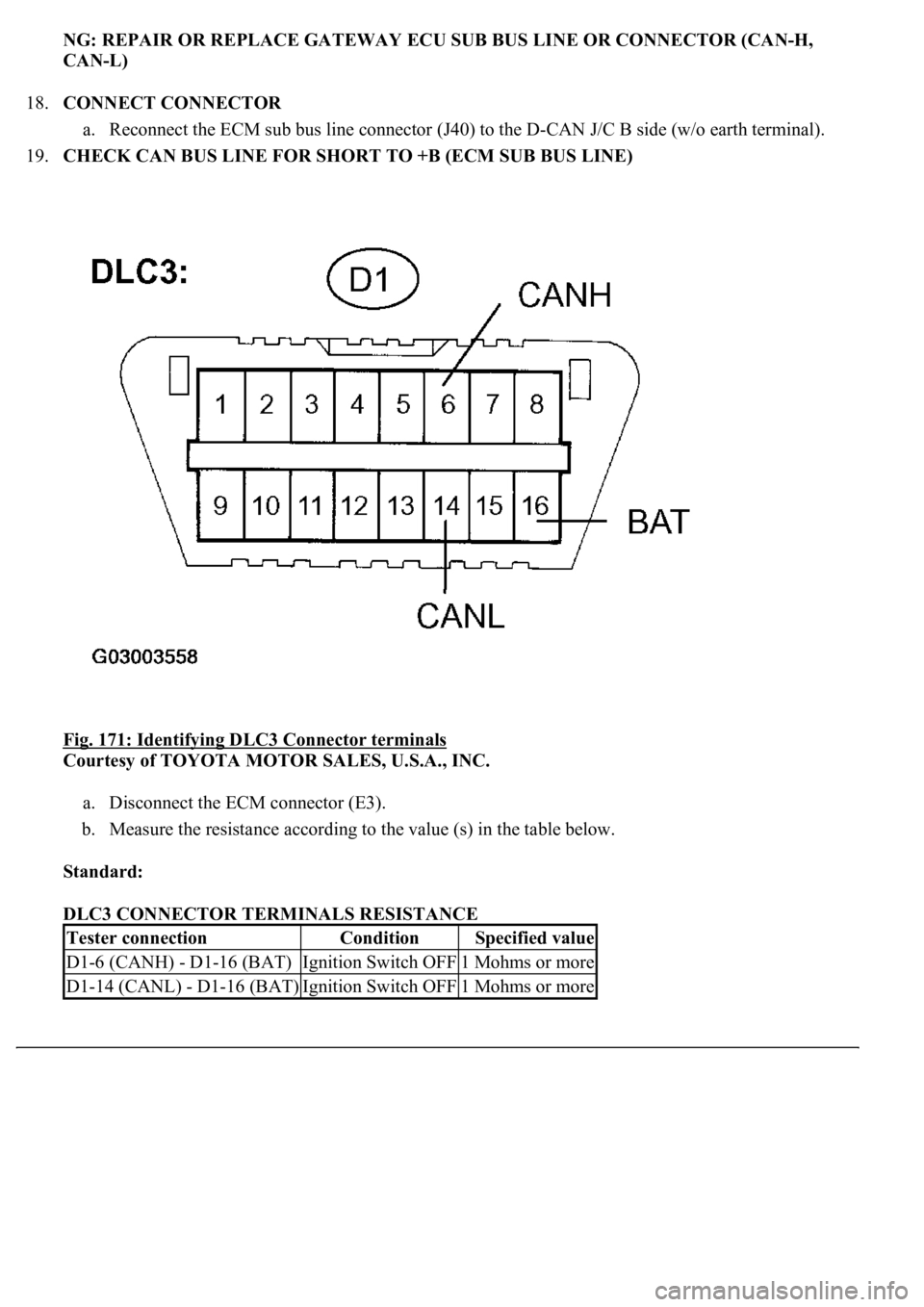
19.CHECK CAN BUS LINE FOR SHORT TO +B (ECM SUB BUS LINE)
Fig. 171: Identifying DLC3 Connector terminals
Courtesy of TOYOTA MOTOR SALES, U.S.A., INC.
a. Disconnect the ECM connector (E3).
b. Measure the resistance according to the value (s) in the table below.
Standard:
DLC3 CONNECTOR TERMINALS RESISTANCE
Tester connectionConditionSpecified value
D1-6 (CANH) - D1-16 (BAT)Ignition Switch OFF1 Mohms or more
D1-14 (CANL) - D1-16 (BAT)Ignition Switch OFF1 Mohms or more
Page 1382 of 4500
OK: REPLACE ECM (SEE REPLACEMENT)
NG: REPAIR OR REPLACE ECM SUB BUS LINE OR CONNECTOR (CAN-H, CAN-L)
20.CONNECT CONNECTOR
a. Reconnect the skid control ECU sub bus line connector (J41) to the D-CAN J/C B side (w/o earth
terminal).
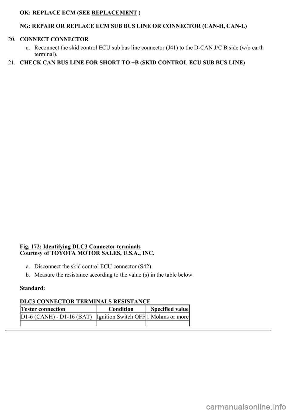
21.CHECK CAN BUS LINE FOR SHORT TO +B (SKID CONTROL ECU SUB BUS LINE)
Fig. 172: Identifying DLC3 Connector terminals
Courtesy of TOYOTA MOTOR SALES, U.S.A., INC.
a. Disconnect the skid control ECU connector (S42).
b. Measure the resistance according to the value (s) in the table below.
Standard:
DLC3 CONNECTOR TERMINALS RESISTANCE
Tester connectionConditionSpecified value
D1-6 (CANH) - D1-16 (BAT)Ignition Switch OFF1 Mohms or more
Page 1383 of 4500
OK: REPLACE SKID CONTROL ECU WITH ACTUATOR (SEE REPLACEMENT )
NG: REPAIR OR REPLACE SKID CONTROL ECU SUB BUS LINE OR CONNECTOR (CAN-
H, CAN-L)
22.CONNECT CONNECTOR
a. Reconnect the steering sensor sub bus line connector (J43) to the D-CAN J/C B side (w/o earth
terminal).
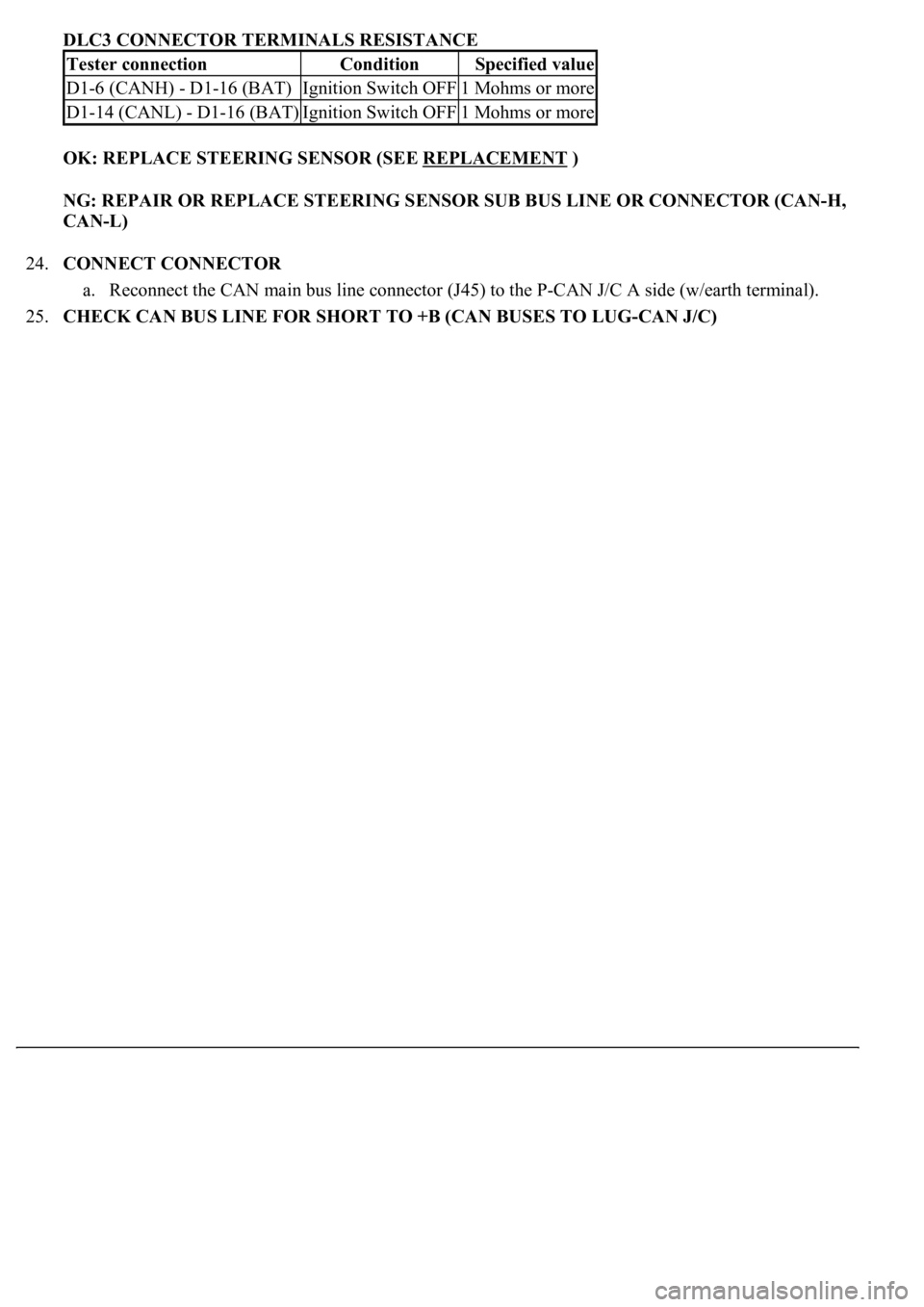
23.CHECK CAN BUS LINE FOR SHORT TO +B (STEERING SENSOR SUB BUS LINE)
Fig. 173: Identifying DLC3 Connector terminals
Courtesy of TOYOTA MOTOR SALES, U.S.A., INC.
a. Disconnect the steering sensor connector (S16).
b. Measure the resistance according to the value (s) in the table below.
Standard:
D1 -14 (CANL) - D1-16 (BAT)Ignition Switch OFF1 Mohms or more
Page 1384 of 4500
DLC3 CONNECTOR TERMINALS RESISTANCE
OK: REPLACE STEERING SENSOR (SEE REPLACEMENT
)
NG: REPAIR OR REPLACE STEERING SENSOR SUB BUS LINE OR CONNECTOR (CAN-H,
CAN-L)
24.CONNECT CONNECTOR
a. Reconnect the CAN main bus line connector (J45) to the P-CAN J/C A side (w/earth terminal).
25.CHECK CAN BUS LINE FOR SHORT TO +B (CAN BUSES TO LUG-CAN J/C)
Tester connectionConditionSpecified value
D1-6 (CANH) - D1-16 (BAT)Ignition Switch OFF1 Mohms or more
D1-14 (CANL) - D1-16 (BAT)Ignition Switch OFF1 Mohms or more
Page 1385 of 4500
Fig. 174: Disconnecting CAN Main Bus Line Connector (J49) From LUG-CAN J/C A Side
(W/Earth Terminal)
Courtesy of TOYOTA MOTOR SALES, U.S.A., INC.
a. Disconnect the CAN main bus line connector (J49) from the LUG-CAN J/C A side (w/earth
terminal).
Page 1386 of 4500
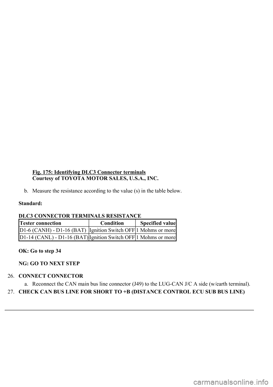
Fig. 175: Identifying DLC3 Connector terminals
Courtesy of TOYOTA MOTOR SALES, U.S.A., INC.
b. Measure the resistance according to the value (s) in the table below.
Standard:
DLC3 CONNECTOR TERMINALS RESISTANCE
OK: Go to step 34
NG: GO TO NEXT STEP
26.CONNECT CONNECTOR
a. Reconnect the CAN main bus line connector (J49) to the LUG-CAN J/C A side (w/earth terminal).
27.CHECK CAN BUS LINE FOR SHORT TO +B (DISTANCE CONTROL ECU SUB BUS LINE)
Tester connectionConditionSpecified value
D1-6 (CANH) - D1-16 (BAT)Ignition Switch OFF1 Mohms or more
D1-14 (CANL) - D1-16 (BAT)Ignition Switch OFF1 Mohms or more
Page 1387 of 4500
Fig. 176: Disconnecting Distance Control ECU Sub Bus Line Connector (J48) From P-CAN J/C B
Side (W/O Earth Terminal)
Courtesy of TOYOTA MOTOR SALES, U.S.A., INC.
a. Disconnect the distance control ECU sub bus line connector (J48) from the P-CAN J/C B side (w/o
earth terminal).
Page 1388 of 4500
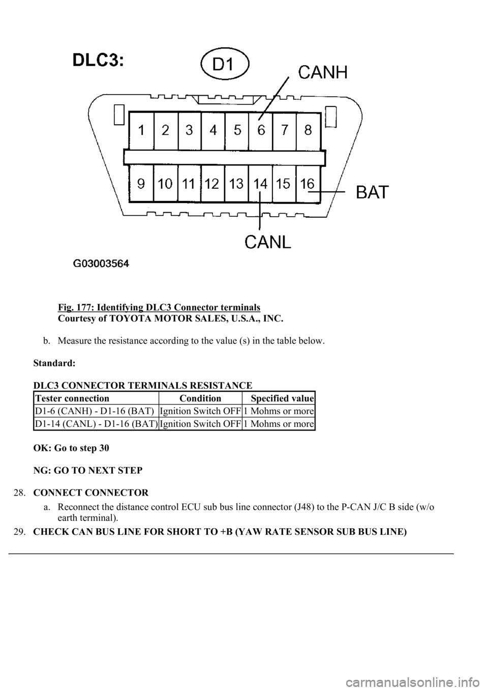
Fig. 177: Identifying DLC3 Connector terminals
Courtesy of TOYOTA MOTOR SALES, U.S.A., INC.
b. Measure the resistance according to the value (s) in the table below.
Standard:
DLC3 CONNECTOR TERMINALS RESISTANCE
OK: Go to step 30
NG: GO TO NEXT STEP
28.CONNECT CONNECTOR
a. Reconnect the distance control ECU sub bus line connector (J48) to the P-CAN J/C B side (w/o
earth terminal).
29.CHECK CAN BUS LINE FOR SHORT TO +B (YAW RATE SENSOR SUB BUS LINE)
Tester connectionConditionSpecified value
D1-6 (CANH) - D1-16 (BAT)Ignition Switch OFF1 Mohms or more
D1-14 (CANL) - D1-16 (BAT)Ignition Switch OFF1 Mohms or more
Page 1389 of 4500
Fig. 178: Disconnecting Yaw Rate Sensor Sub Bus Line Connector (J44) From P-CAN J/C A Side
(W/Earth Terminal)
Courtesy of TOYOTA MOTOR SALES, U.S.A., INC.
a. Disconnect the yaw rate sensor sub bus line connector (J44) from the P-CAN J/C A side (w/earth
terminal).
Page 1390 of 4500
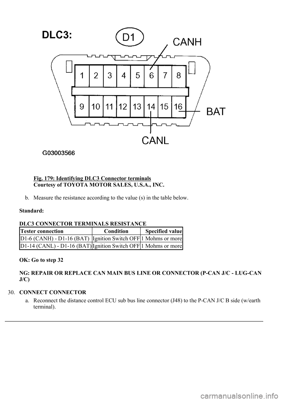
Fig. 179: Identifying DLC3 Connector terminals
Courtesy of TOYOTA MOTOR SALES, U.S.A., INC.
b. Measure the resistance according to the value (s) in the table below.
Standard:
DLC3 CONNECTOR TERMINALS RESISTANCE
OK: Go to step 32
NG: REPAIR OR REPLACE CAN MAIN BUS LINE OR CONNECTOR (P-CAN J/C - LUG-CAN
J/C)
30.CONNECT CONNECTOR
a. Reconnect the distance control ECU sub bus line connector (J48) to the P-CAN J/C B side (w/earth
terminal).
Tester connectionConditionSpecified value
D1-6 (CANH) - D1-16 (BAT)Ignition Switch OFF1 Mohms or more
D1-14 (CANL) - D1-16 (BAT)Ignition Switch OFF1 Mohms or more
Trending: tail light replacement, AUX, steering interlock cable, adding oil, gas type, c1751, air conditioning
