LEXUS LS430 2003 Factory Repair Manual
Manufacturer: LEXUS, Model Year: 2003,
Model line: LS430,
Model: LEXUS LS430 2003
Pages: 4500, PDF Size: 87.45 MB
LEXUS LS430 2003 Factory Repair Manual
LS430 2003
LEXUS
LEXUS
https://www.carmanualsonline.info/img/36/57050/w960_57050-0.png
LEXUS LS430 2003 Factory Repair Manual
Trending: Identifying ac, lights, oil change, height, Identifying condition, ignition, remote control
Page 1481 of 4500
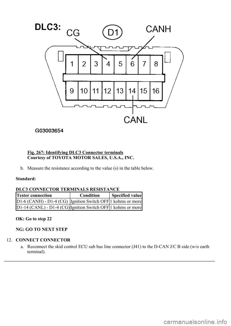
Fig. 267: Identifying DLC3 Connector terminals
Courtesy of TOYOTA MOTOR SALES, U.S.A., INC.
b. Measure the resistance according to the value (s) in the table below.
Standard:
DLC3 CONNECTOR TERMINALS RESISTANCE
OK: Go to step 22
NG: GO TO NEXT STEP
12.CONNECT CONNECTOR
a. Reconnect the skid control ECU sub bus line connector (J41) to the D-CAN J/C B side (w/o earth
terminal).
Tester connectionConditionSpecified value
D1-6 (CANH) - D1-4 (CG)Ignition Switch OFF1 kohms or more
D1-14 (CANL) - D1-4 (CG)Ignition Switch OFF1 kohms or more
Page 1482 of 4500
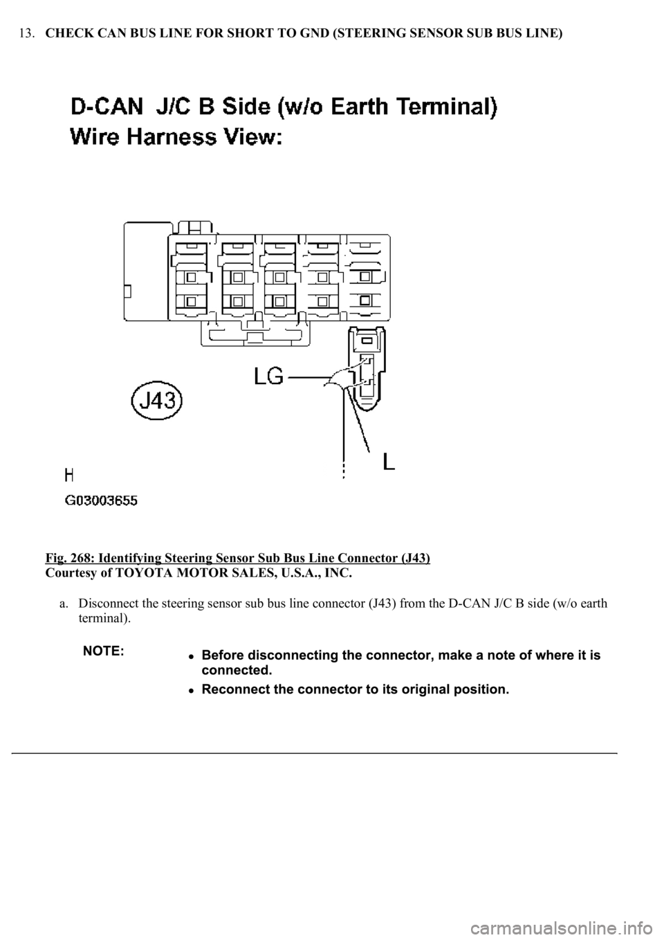
13.CHECK CAN BUS LINE FOR SHORT TO GND (STEERING SENSOR SUB BUS LINE)
Fig. 268: Identifying Steering Sensor Sub Bus Line Connector (J43)
Courtesy of TOYOTA MOTOR SALES, U.S.A., INC.
a. Disconnect the steering sensor sub bus line connector (J43) from the D-CAN J/C B side (w/o earth
terminal).
Page 1483 of 4500
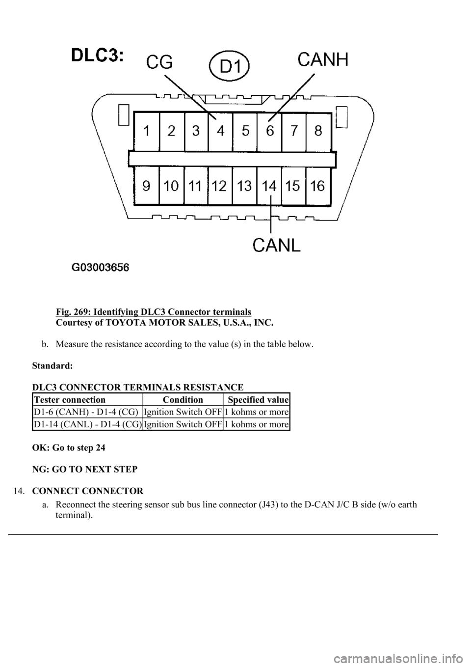
Fig. 269: Identifying DLC3 Connector terminals
Courtesy of TOYOTA MOTOR SALES, U.S.A., INC.
b. Measure the resistance according to the value (s) in the table below.
Standard:
DLC3 CONNECTOR TERMINALS RESISTANCE
OK: Go to step 24
NG: GO TO NEXT STEP
14.CONNECT CONNECTOR
a. Reconnect the steering sensor sub bus line connector (J43) to the D-CAN J/C B side (w/o earth
terminal).
Tester connectionConditionSpecified value
D1-6 (CANH) - D1-4 (CG)Ignition Switch OFF1 kohms or more
D1-14 (CANL) - D1-4 (CG)Ignition Switch OFF1 kohms or more
Page 1484 of 4500
15.CHECK CAN BUS LINE FOR SHORT TO GND (D-CAN J/C)
Fig. 270: Disconnecting CAN Main Bus Line Connector (J37) From D
-CAN J/C A Side (W/Earth
Terminal)
Courtesy of TOYOTA MOTOR SALES, U.S.A., INC.
a. Disconnect the CAN main bus line connector (J37) from the D-CAN J/C A side (w/earth terminal).
Page 1485 of 4500
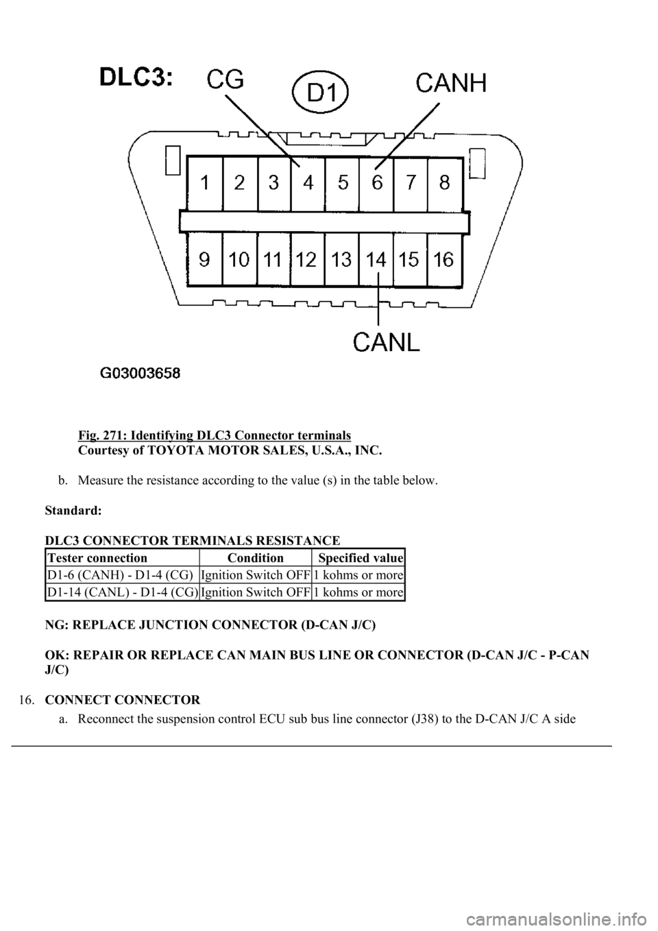
Fig. 271: Identifying DLC3 Connector terminals
Courtesy of TOYOTA MOTOR SALES, U.S.A., INC.
b. Measure the resistance according to the value (s) in the table below.
Standard:
DLC3 CONNECTOR TERMINALS RESISTANCE
NG: REPLACE JUNCTION CONNECTOR (D-CAN J/C)
OK: REPAIR OR REPLACE CAN MAIN BUS LINE OR CONNECTOR (D-CAN J/C - P-CAN
J/C)
16.CONNECT CONNECTOR
a. Reconnect the suspension control ECU sub bus line connector (J38) to the D-CAN J/C A side
Tester connectionConditionSpecified value
D1-6 (CANH) - D1-4 (CG)Ignition Switch OFF1 kohms or more
D1-14 (CANL) - D1-4 (CG)Ignition Switch OFF1 kohms or more
Page 1486 of 4500
(w/earth terminal).
17.CHECK CAN BUS LINE FOR SHORT TO GND (SUSPENSION CONTROL ECU SUB BUS
LINE)
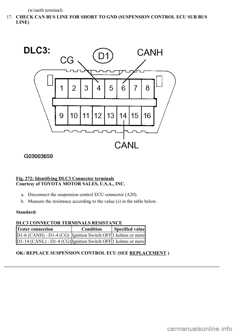
Fig. 272: Identifying DLC3 Connector terminals
Courtesy of TOYOTA MOTOR SALES, U.S.A., INC.
a. Disconnect the suspension control ECU connector (A20).
b. Measure the resistance according to the value (s) in the table below.
Standard:
DLC3 CONNECTOR TERMINALS RESISTANCE
OK: REPLACE SUSPENSION CONTROL ECU (SEE REPLACEMENT
)
Tester connectionConditionSpecified value
D1-6 (CANH) - D1-4 (CG)Ignition Switch OFF1 kohms or more
D1-14 (CANL) - D1-4 (CG)Ignition Switch OFF1 kohms or more
Page 1487 of 4500
NG: REPAIR OR REPLACE SUSPENSION CONTROL ECU SUB BUS LINE OR CONNECTOR
(CAN-H, CAN-L)
18.CONNECT CONNECTOR
a. Reconnect the gateway ECU sub bus line connector (J36) to the D-CAN J/C A side (w/earth
terminal).
19.CHECK CAN BUS LINE FOR SHORT TO GND (GATEWAY ECU SUB BUS LINE)
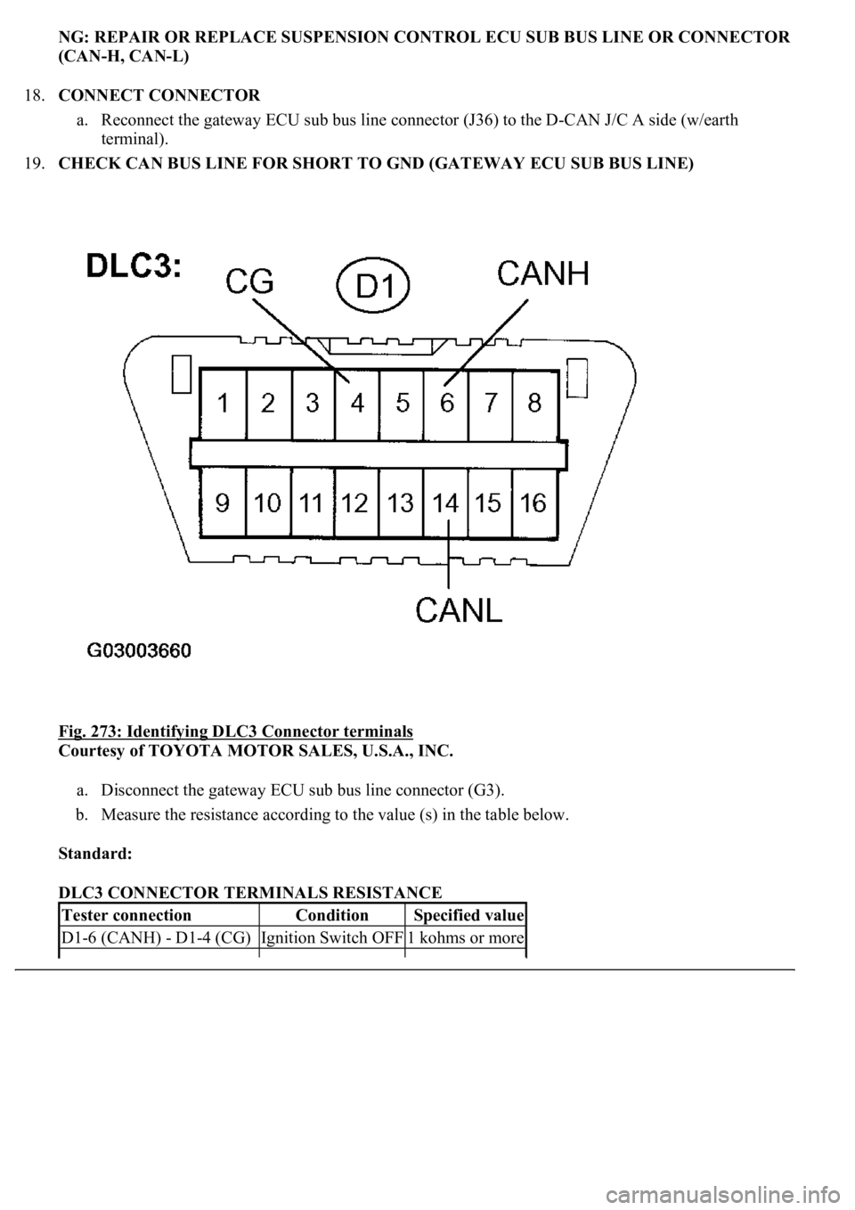
Fig. 273: Identifying DLC3 Connector terminals
Courtesy of TOYOTA MOTOR SALES, U.S.A., INC.
a. Disconnect the gateway ECU sub bus line connector (G3).
b. Measure the resistance according to the value (s) in the table below.
Standard:
DLC3 CONNECTOR TERMINALS RESISTANCE
Tester connectionConditionSpecified value
D1-6 (CANH) - D1-4 (CG)Ignition Switch OFF1 kohms or more
Page 1488 of 4500
OK: REPLACE GATEWAY ECU
NG: REPAIR OR REPLACE GATEWAY ECU SUB BUS LINE OR CONNECTOR (CAN-H,
CAN-L)
20.CONNECT CONNECTOR
a. Reconnect the ECM sub bus line connector (J40) to the D-CAN J/C B side (w/o earth terminal).
21.CHECK CAN BUS LINE FOR SHORT TO GND (ECM SUB BUS LINE)
Fig. 274: Identifying DLC3 Connector terminals
Courtesy of TOYOTA MOTOR SALES, U.S.A., INC.
a. Disconnect the ECM connector (E3).
b. Measure the resistance according to the value (s) in the table below.
Standard:
D1-14 (CANL) - D1-4 (CG)Ignition Switch OFF1 kohms or more
Page 1489 of 4500
DLC3 CONNECTOR TERMINALS RESISTANCE
OK: REPLACE ECM (SEE REPLACEMENT
)
NG: REPAIR OR REPLACE ECM SUB BUS LINE OR CONNECTOR (CAN-H, CAN-L)
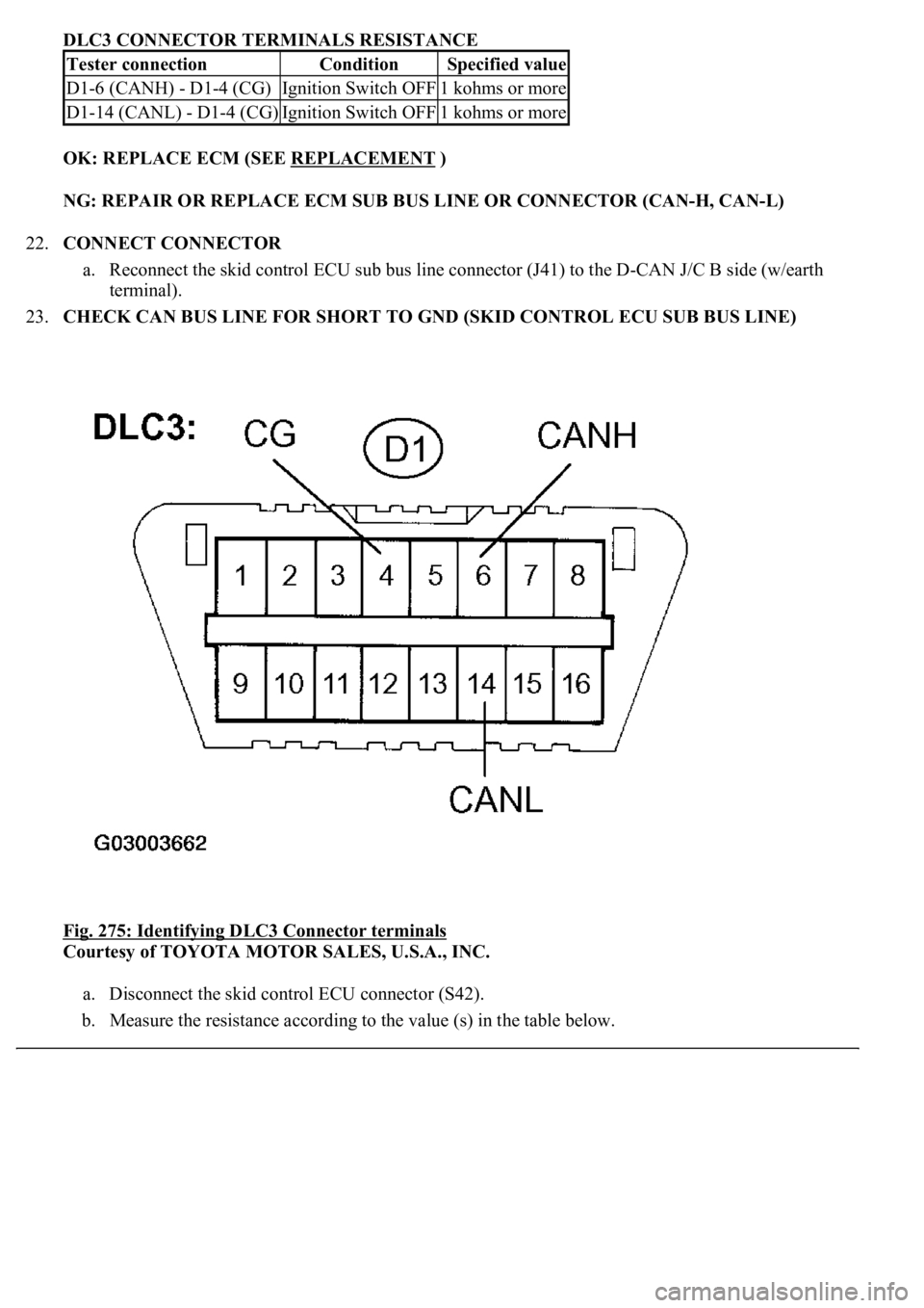
22.CONNECT CONNECTOR
a. Reconnect the skid control ECU sub bus line connector (J41) to the D-CAN J/C B side (w/earth
terminal).
23.CHECK CAN BUS LINE FOR SHORT TO GND (SKID CONTROL ECU SUB BUS LINE)
Fig. 275: Identifying DLC3 Connector terminals
Courtesy of TOYOTA MOTOR SALES, U.S.A., INC.
a. Disconnect the skid control ECU connector (S42).
b. Measure the resistance according to the value (s) in the table below.
Tester connectionConditionSpecified value
D1-6 (CANH) - D1-4 (CG)Ignition Switch OFF1 kohms or more
D1-14 (CANL) - D1-4 (CG)Ignition Switch OFF1 kohms or more
Page 1490 of 4500
Standard:
DLC3 CONNECTOR TERMINALS RESISTANCE
OK: REPLACE SKID CONTROL ECU WITH ACTUATOR (SEE REPLACEMENT
)
NG: REPAIR OR REPLACE SKID CONTROL ECU SUB BUS LINE OR CONNECTOR (CAN-
H, CAN-L)
24.CONNECT CONNECTOR
a. Reconnect the steering sensor sub bus line connector (J43) to the D-CAN J/C B side (w/o earth
terminal).
25.CHECK CAN BUS LINE FOR SHORT TO GND (STEERING SENSOR SUB BUS LINE)
Fig. 276: Identifying DLC3 Connector terminals
Courtesy of TOYOTA MOTOR SALES, U.S.A., INC.
Tester connectionConditionSpecified value
D1-6 (CANH) D1-4 (CG)Ignition Switch OFF1 kohms or more
D1-14 (CANL) D1-4 (CG)Ignition Switch OFF1 kohms or more
Trending: roof rack, height, glove box, radiator cap, radio antenna, window, park assist
