LEXUS LS430 2003 Factory Repair Manual
Manufacturer: LEXUS, Model Year: 2003,
Model line: LS430,
Model: LEXUS LS430 2003
Pages: 4500, PDF Size: 87.45 MB
LEXUS LS430 2003 Factory Repair Manual
LS430 2003
LEXUS
LEXUS
https://www.carmanualsonline.info/img/36/57050/w960_57050-0.png
LEXUS LS430 2003 Factory Repair Manual
Trending: Compressor control valve, fuse diagram, wheel size, Expansion Valve, lock, content, roof rack
Page 1501 of 4500
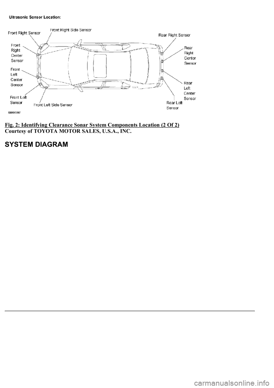
<0029004c004a001100030015001d0003002c0047004800510057004c0049005c004c0051004a00030026004f004800440055004400510046004800030036005200510044005500030036005c00560057004800500003002600520050005300520051004800
51005700560003002f0052004600440057004c005200510003[(2 Of 2)
Courtesy of TOYOTA MOTOR SALES, U.S.A., INC.
Page 1502 of 4500
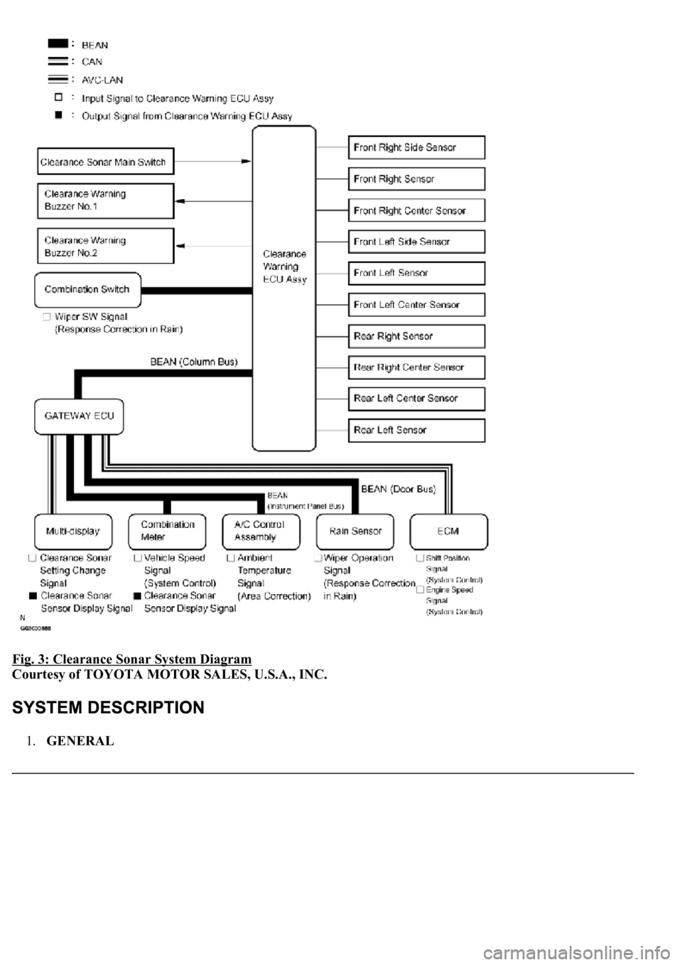
Fig. 3: Clearance Sonar System Diagram
Courtesy of TOYOTA MOTOR SALES, U.S.A., INC.
1.GENERAL
Page 1503 of 4500
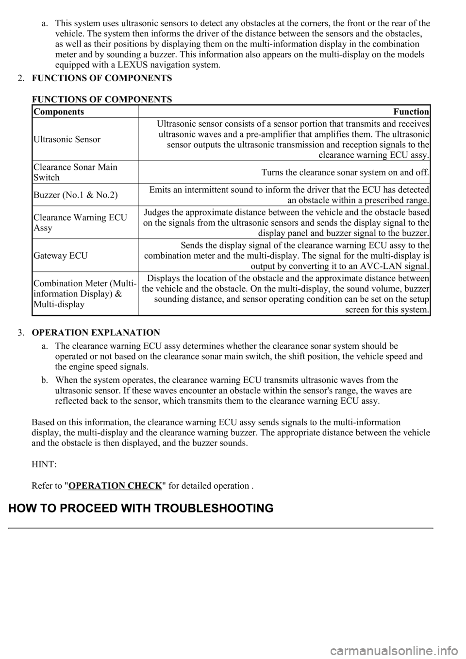
a. This system uses ultrasonic sensors to detect any obstacles at the corners, the front or the rear of the
vehicle. The system then informs the driver of the distance between the sensors and the obstacles,
as well as their positions by displaying them on the multi-information display in the combination
meter and by sounding a buzzer. This information also appears on the multi-display on the models
equipped with a LEXUS navigation system.
2.FUNCTIONS OF COMPONENTS
FUNCTIONS OF COMPONENTS
3.OPERATION EXPLANATION
a. The clearance warning ECU assy determines whether the clearance sonar system should be
operated or not based on the clearance sonar main switch, the shift position, the vehicle speed and
the engine speed signals.
b. When the system operates, the clearance warning ECU transmits ultrasonic waves from the
ultrasonic sensor. If these waves encounter an obstacle within the sensor's range, the waves are
reflected back to the sensor, which transmits them to the clearance warning ECU assy.
Based on this information, the clearance warning ECU assy sends signals to the multi-information
display, the multi-display and the clearance warning buzzer. The appropriate distance between the vehicle
and the obstacle is then displayed, and the buzzer sounds.
HINT:
Refer to "OPERATION CHECK
" for detailed operation .
ComponentsFunction
Ultrasonic Sensor
Ultrasonic sensor consists of a sensor portion that transmits and receives
ultrasonic waves and a pre-amplifier that amplifies them. The ultrasonic
sensor outputs the ultrasonic transmission and reception signals to the
clearance warning ECU assy.
Clearance Sonar Main
SwitchTurns the clearance sonar system on and off.
Buzzer (No.1 & No.2)Emits an intermittent sound to inform the driver that the ECU has detected
an obstacle within a prescribed range.
Clearance Warning ECU
AssyJudges the approximate distance between the vehicle and the obstacle based
on the signals from the ultrasonic sensors and sends the display signal to the
display panel and buzzer signal to the buzzer.
Gateway ECU
Sends the display signal of the clearance warning ECU assy to the
combination meter and the multi-display. The signal for the multi-display is
output by converting it to an AVC-LAN signal.
Combination Meter (Multi-
information Display) &
Multi-displayDisplays the location of the obstacle and the approximate distance between
the vehicle and the obstacle. On the multi-display, the sound volume, buzzer
sounding distance, and sensor operating condition can be set on the setup
screen for this system.
Page 1504 of 4500
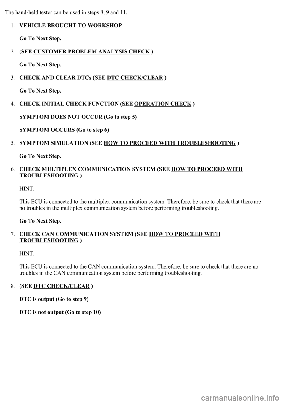
The hand-held tester can be used in steps 8, 9 and 11.
1.VEHICLE BROUGHT TO WORKSHOP
Go To Next Step.
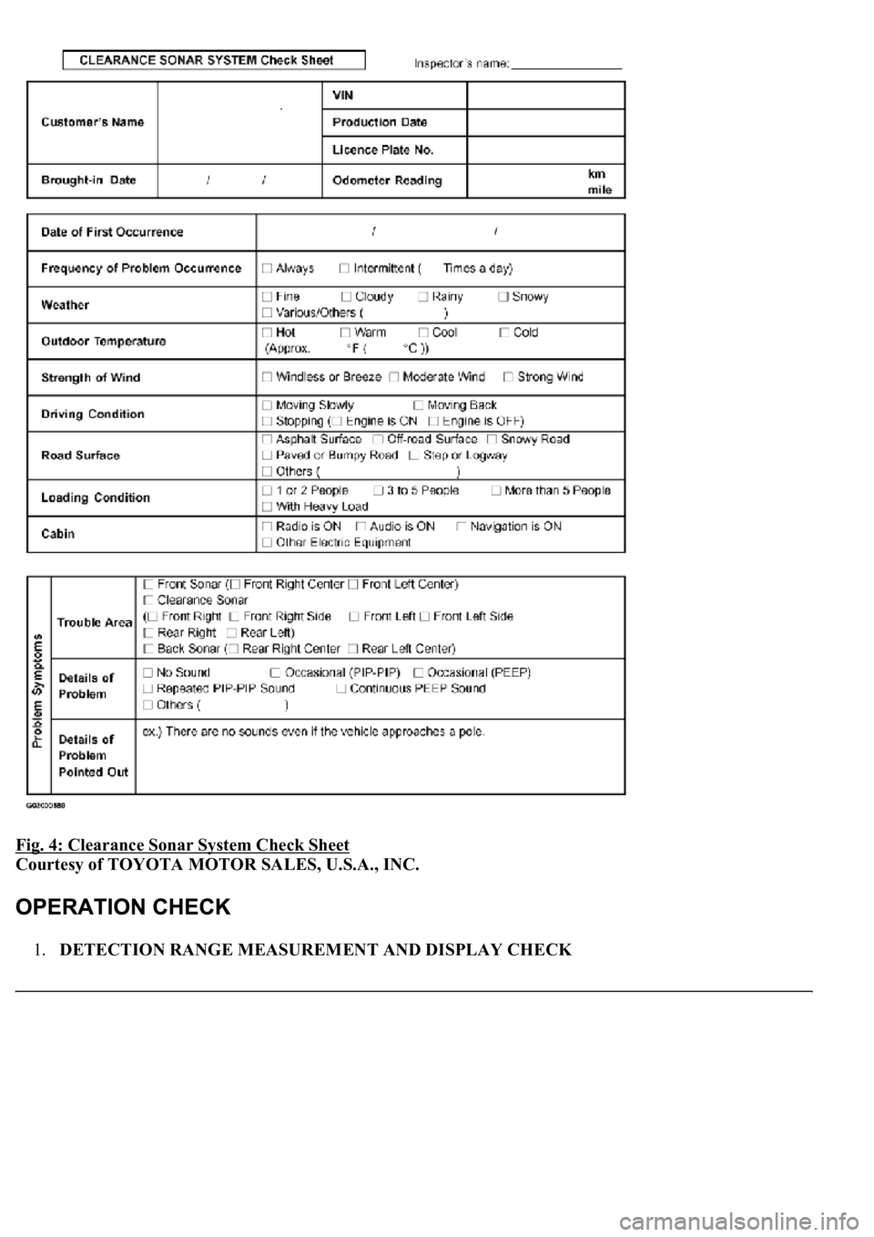
2.(SEE CUSTOMER PROBLEM ANALYSIS CHECK
)
Go To Next Step.
3.CHECK AND CLEAR DTCs (SEE DTC CHECK/CLEAR
)
Go To Next Step.
4.CHECK INITIAL CHECK FUNCTION (SEE OPERATION CHECK
)
SYMPTOM DOES NOT OCCUR (Go to step 5)
SYMPTOM OCCURS (Go to step 6)
5.SYMPTOM SIMULATION (SEE HOW TO PROCEED WITH TROUBLESHOOTING
)
Go To Next Step.
6.CHECK MULTIPLEX COMMUNICATION SYSTEM (SEE HOW TO PROCEED WITH
TROUBLESHOOTING )
HINT:
This ECU is connected to the multiplex communication system. Therefore, be sure to check that there are
no troubles in the multiplex communication system before performing troubleshooting.
Go To Next Step.
7.CHECK CAN COMMUNICATION SYSTEM (SEE HOW TO PROCEED WITH
TROUBLESHOOTING )
HINT:
This ECU is connected to the CAN communication system. Therefore, be sure to check that there are no
troubles in the CAN communication system before performing troubleshooting.
8.(SEE DTC CHECK/CLEAR
)
DTC is output (Go to step 9)
DTC is not output (Go to step 10)
Page 1505 of 4500
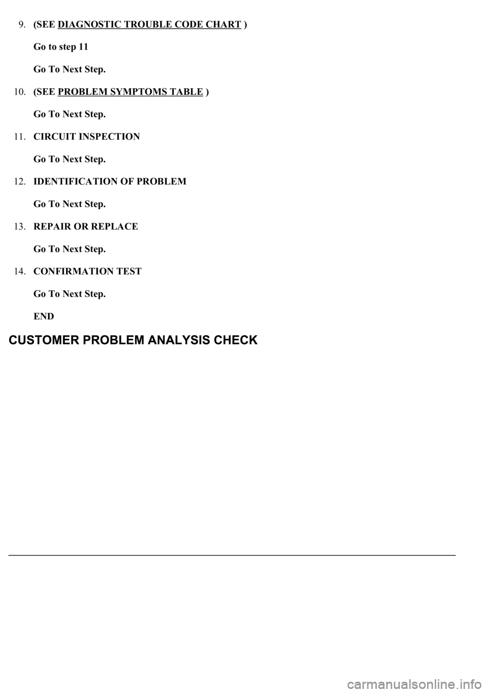
9.(SEE DIAGNOSTIC TROUBLE CODE CHART )
Go to step 11
Go To Next Step.
10.(SEE PROBLEM SYMPTOMS TABLE
)
Go To Next Step.
11.CIRCUIT INSPECTION
Go To Next Step.
12.IDENTIFICATION OF PROBLEM
Go To Next Step.
13.REPAIR OR REPLACE
Go To Next Step.
14.CONFIRMATION TEST
Go To Next Step.
END
Page 1506 of 4500
Fig. 4: Clearance Sonar System Check Sheet
Courtesy of TOYOTA MOTOR SALES, U.S.A., INC.
1.DETECTION RANGE MEASUREMENT AND DISPLAY CHECK
Page 1507 of 4500
a. Turn the ignition switch to the ON position.
b. Move the shift lever to the D position (when the front sonar and the front clearance sonar are
checked).
c. Move the shift lever to the R position (when the back sonar and the rear clearance sonar are
checked).
d. Turn the clearance sonar main switch on.
e. Move a diameter 60 mm (2.36 in.) pole around the sensor to measure the detection range of the
sensor.
Page 1508 of 4500
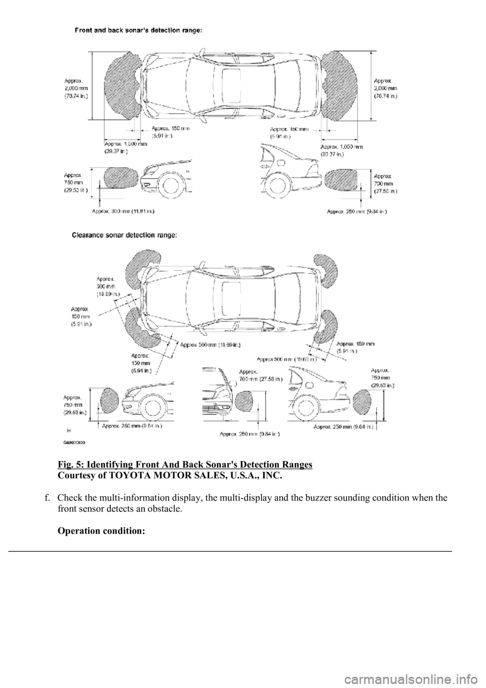
Fig. 5: Identifying Front And Back Sonar's Detection Ranges
Courtesy of TOYOTA MOTOR SALES, U.S.A., INC.
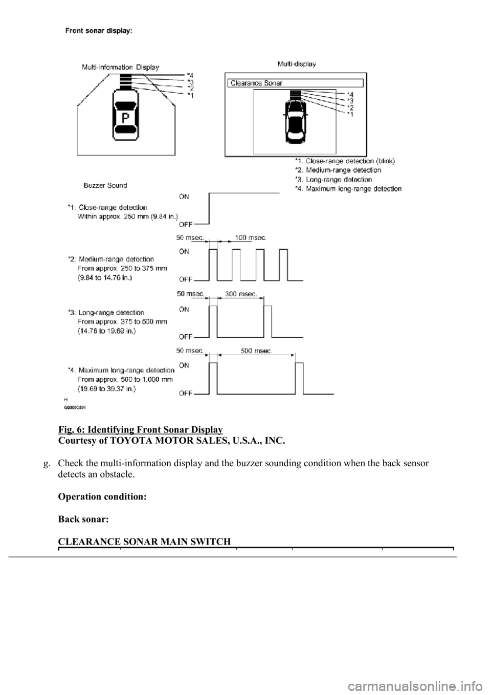
f. Check the multi-information display, the multi-display and the buzzer sounding condition when the
front sensor detects an obstacle.
Operation condition:
Page 1509 of 4500
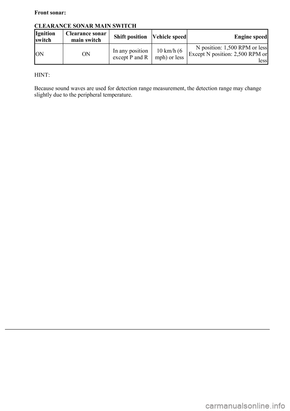
Front sonar:
CLEARANCE SONAR MAIN SWITCH
HINT:
Because sound waves are used for detection range measurement, the detection range may change
sli
ghtly due to the peripheral temperature.
Ignition
switchClearance sonar
main switchShift positionVehicle speedEngine speed
ONONIn any position
except P and R10 km/h (6
mph) or lessN position: 1,500 RPM or less
Except N position: 2,500 RPM or
less
Page 1510 of 4500
Fig. 6: Identifying Front Sonar Display
Courtesy of TOYOTA MOTOR SALES, U.S.A., INC.
g. Check the multi-information display and the buzzer sounding condition when the back sensor
detects an obstacle.
Operation condition:
Back sonar:
CLEARANCE SONAR MAIN SWITCH
Trending: Speedometer, spare tire, low beam, fuel, heating, service, cylinder head
