LEXUS LS430 2003 Factory Repair Manual
Manufacturer: LEXUS, Model Year: 2003, Model line: LS430, Model: LEXUS LS430 2003Pages: 4500, PDF Size: 87.45 MB
Page 1521 of 4500
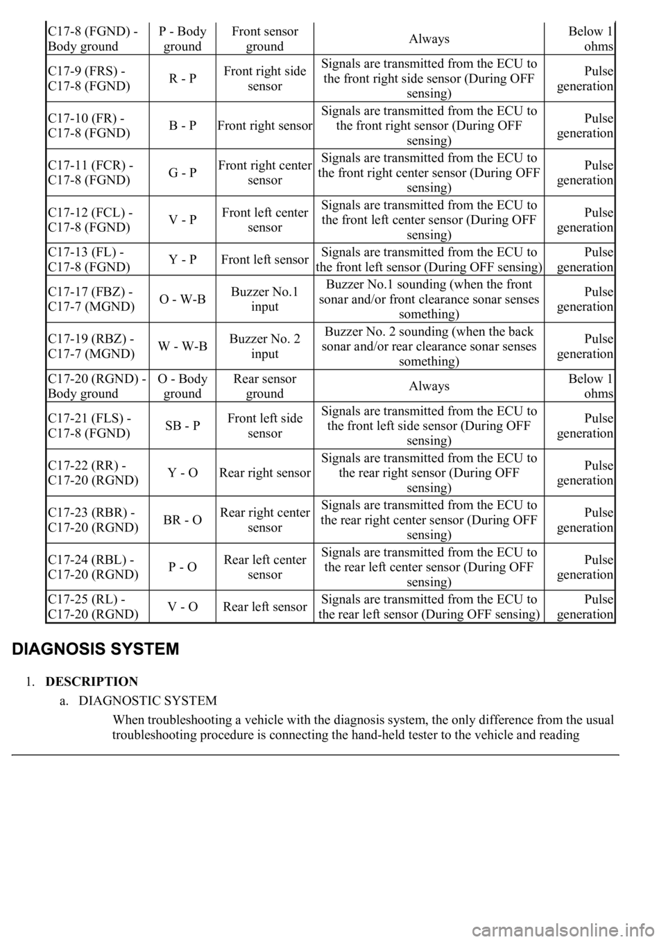
1.DESCRIPTION
a. DIAGNOSTIC SYSTEM
When troubleshooting a vehicle with the diagnosis system, the only difference from the usual
troubleshootin
g procedure is connecting the hand-held tester to the vehicle and reading
C17-8 (FGND) -
Body groundP - Body
groundFront sensor
groundAlwaysBelow 1
ohms
C17-9 (FRS) -
C17-8 (FGND)R - PFront right side
sensorSignals are transmitted from the ECU to
the front right side sensor (During OFF
sensing)Pulse
generation
C17-10 (FR) -
C17-8 (FGND)B - PFront right sensor
Signals are transmitted from the ECU to
the front right sensor (During OFF
sensing)Pulse
generation
C17-11 (FCR) -
C17-8 (FGND)G - PFront right center
sensorSignals are transmitted from the ECU to
the front right center sensor (During OFF
sensing)Pulse
generation
C17-12 (FCL) -
C17-8 (FGND)V - PFront left center
sensorSignals are transmitted from the ECU to
the front left center sensor (During OFF
sensing)Pulse
generation
C17-13 (FL) -
C17-8 (FGND)Y - PFront left sensorSignals are transmitted from the ECU to
the front left sensor (During OFF sensing)Pulse
generation
C17-17 (FBZ) -
C17-7 (MGND)O - W-BBuzzer No.1
inputBuzzer No.1 sounding (when the front
sonar and/or front clearance sonar senses
something)Pulse
generation
C17-19 (RBZ) -
C17-7 (MGND)W - W-BBuzzer No. 2
inputBuzzer No. 2 sounding (when the back
sonar and/or rear clearance sonar senses
something)Pulse
generation
C17-20 (RGND) -
Body groundO - Body
groundRear sensor
groundAlwaysBelow 1
ohms
C17-21 (FLS) -
C17-8 (FGND)SB - PFront left side
sensorSignals are transmitted from the ECU to
the front left side sensor (During OFF
sensing)Pulse
generation
C17-22 (RR) -
C17-20 (RGND)Y - ORear right sensor
Signals are transmitted from the ECU to
the rear right sensor (During OFF
sensing)Pulse
generation
C17-23 (RBR) -
C17-20 (RGND)BR - ORear right center
sensorSignals are transmitted from the ECU to
the rear right center sensor (During OFF
sensing)Pulse
generation
C17-24 (RBL) -
C17-20 (RGND)P - ORear left center
sensorSignals are transmitted from the ECU to
the rear left center sensor (During OFF
sensing)Pulse
generation
C17-25 (RL) -
C17-20 (RGND)V - ORear left sensorSignals are transmitted from the ECU to
the rear left sensor (During OFF sensing)Pulse
generation
Page 1522 of 4500
various data output from the vehicle's clearance warning ECU.
The clearance warning ECU records DTCs when the computer detects a malfunction in the
computer itself or in its circuits.
To check the DTCs, connect the hand-held tester to the DLC3 on the vehicle. The hand-held
tester enables you to erase the DTCs, activate the several actuators and check the freeze
frame data and data list.
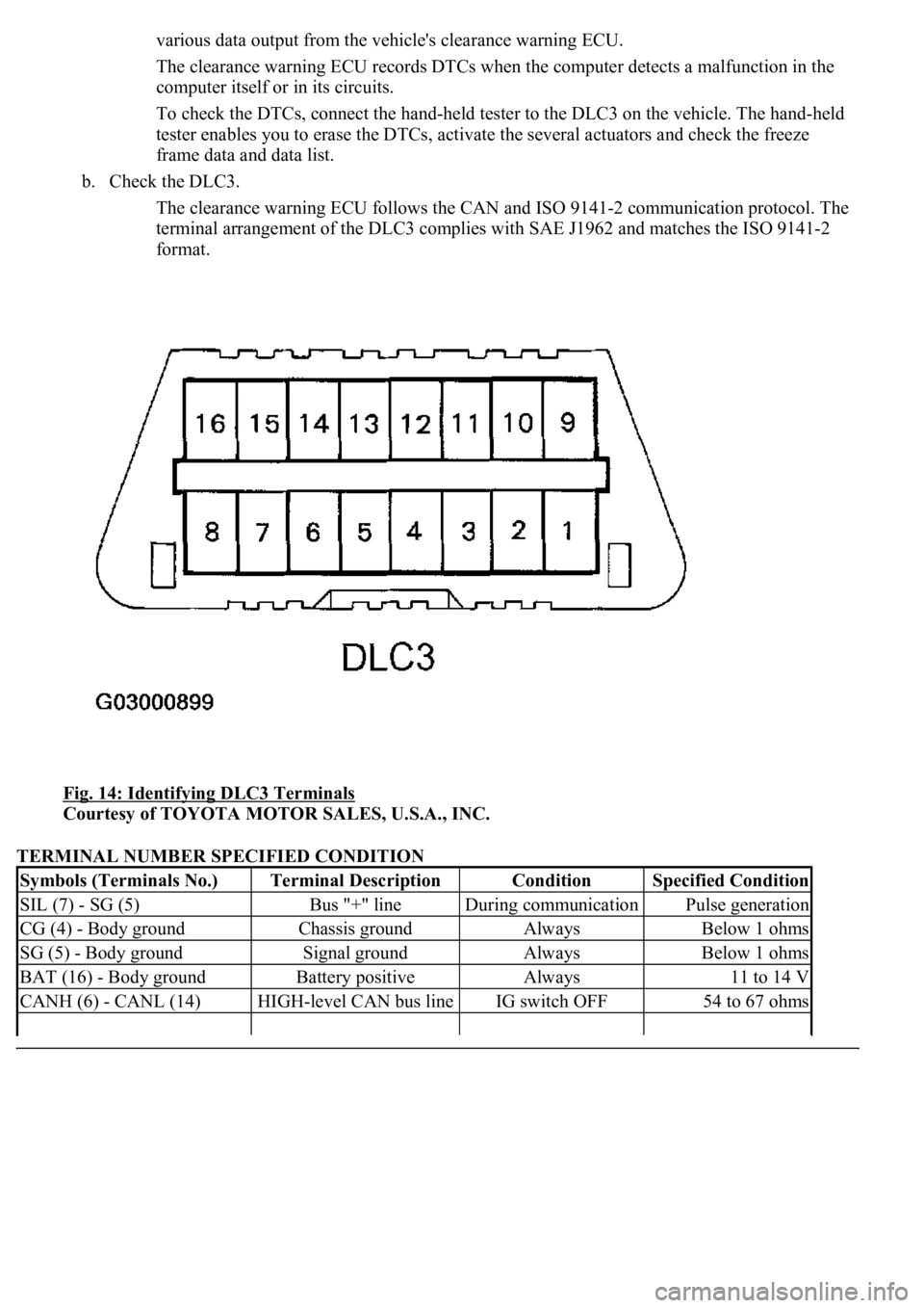
b. Check the DLC3.
The clearance warning ECU follows the CAN and ISO 9141-2 communication protocol. The
terminal arrangement of the DLC3 complies with SAE J1962 and matches the ISO 9141-2
format.
Fig. 14: Identifying DLC3 Terminals
Courtesy of TOYOTA MOTOR SALES, U.S.A., INC.
TERMINAL NUMBER SPECIFIED CONDITION
Symbols (Terminals No.)Terminal DescriptionConditionSpecified Condition
SIL (7) - SG (5)Bus "+" lineDuring communicationPulse generation
CG (4) - Body groundChassis groundAlwaysBelow 1 ohms
SG (5) - Body groundSignal groundAlwaysBelow 1 ohms
BAT (16) - Body groundBattery positiveAlways11 to 14 V
CANH (6) - CANL (14)HIGH-level CAN bus lineIG switch OFF54 to 67 ohms
Page 1523 of 4500
HINT:
If the display shows "UNABLE TO CONNECT TO VEHICLE" after connecting the hand-held tester cable to
the DLC3 and turning the ignition switch to the ON position, there is either a problem with the vehicle or tester.
If communication is normal when connecting the tester to another vehicle, inspect the DLC3 on the
original vehicle.
If communication is still not possible when connecting the tester to another vehicle, the problem is
probably in the tester itself, so consult the Service Department listed in the tester's operator's manual.
1.CHECK DTCs
a. Prepare the hand-held tester.
b. Connect the hand-held tester to the DLC3 at the lower part of the instrument panel.
c. Turn the ignition switch to the ON position and turn the hand-held tester on.
d. Use the hand-held tester to check the DTCs and the freeze frame data, and note or print the results.
(Refer to the operator's manual for operating instructions.)
e. SEE DIAGNOSTIC TROUBLE CODE CHART
to confirm the details of the DTCs.
2.CLEAR DTCs
a. The following procedures clear the DTCs and freeze frame data.
1. When using the hand-held tester:
Operate the hand-held tester. (Refer to the operator's manual for operating
instructions.)
2. When not using the hand-held tester:
Disconnect the battery terminals.
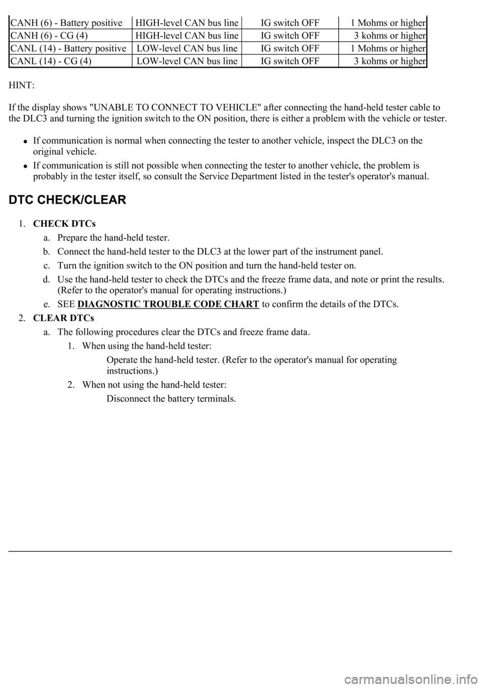
CANH (6) - Battery positiveHIGH-level CAN bus lineIG switch OFF1 Mohms or higher
CANH (6) - CG (4)HIGH-level CAN bus lineIG switch OFF3 kohms or higher
CANL (14) - Battery positiveLOW-level CAN bus lineIG switch OFF1 Mohms or higher
CANL (14) - CG (4)LOW-level CAN bus lineIG switch OFF3 kohms or higher
Page 1524 of 4500
Fig. 15: Connecting Cable Of Hand-Held Tester To Dlc3
Courtesy of TOYOTA MOTOR SALES, U.S.A., INC.
1.DATA LIST
a. Connect the hand-held tester to the DLC3.
b. Turn the ignition switch to the ON position.
c. Operate the hand-held tester according to the steps on the display and select "DATA LIST".
CSONAR:
Page 1525 of 4500
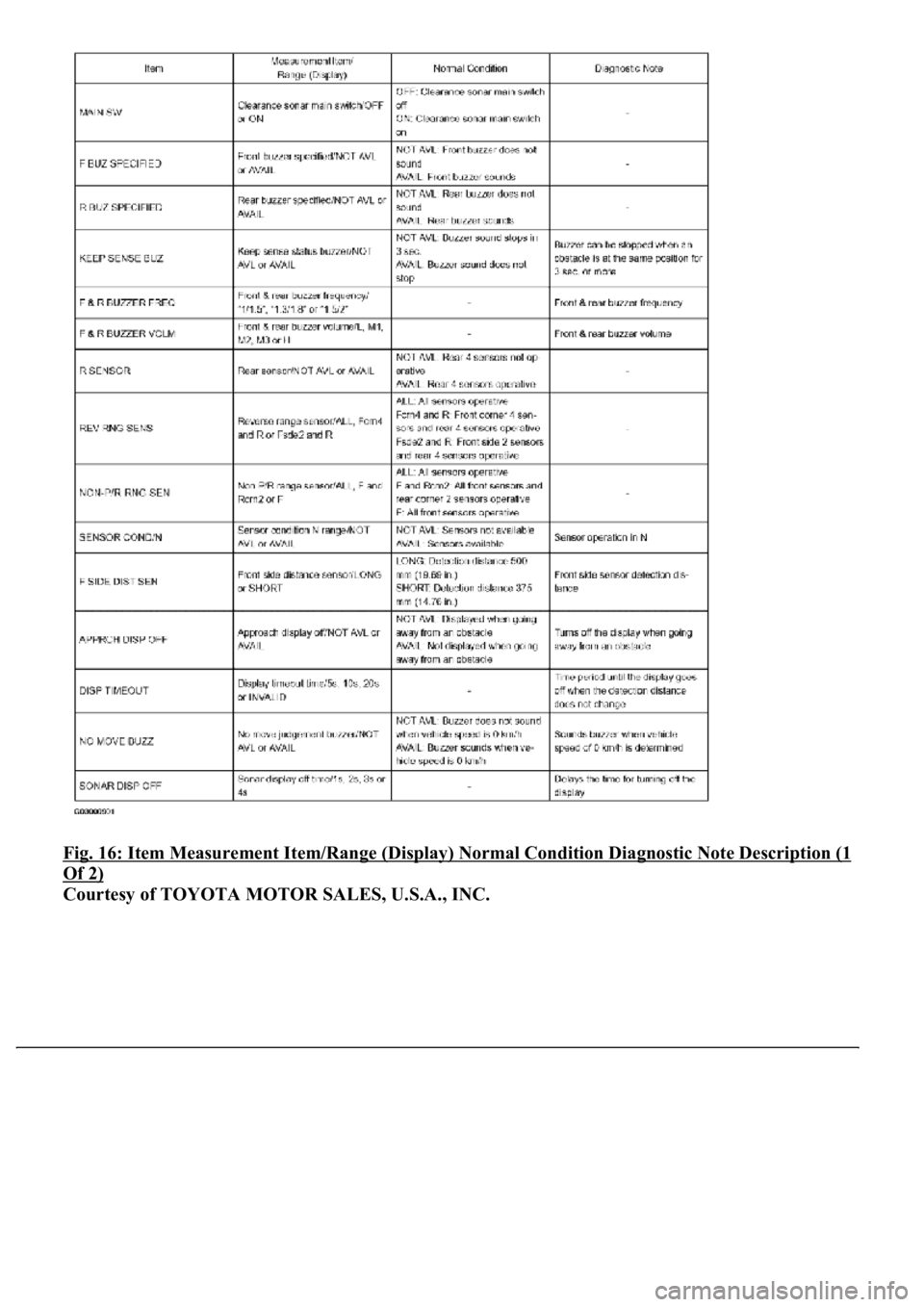
Fig. 16: Item Measurement Item/Range (Display) Normal Condition Diagnostic Note Description (1
Of 2)
Courtesy of TOYOTA MOTOR SALES, U.S.A., INC.
Page 1526 of 4500
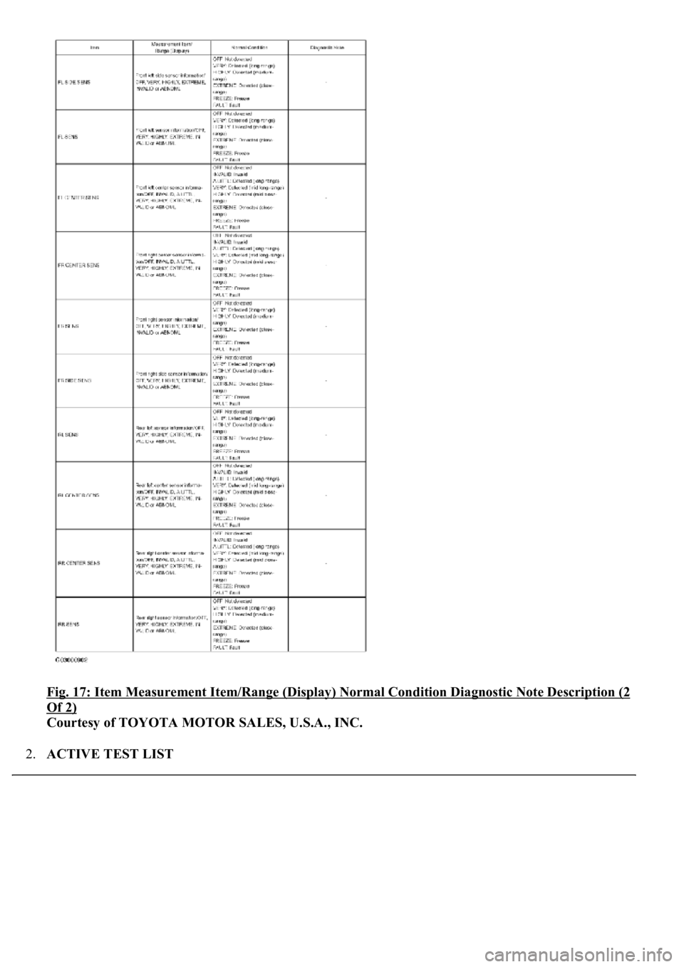
Fig. 17: Item Measurement Item/Range (Display) Normal Condition Diagnostic Note Description (2
Of 2)
Courtesy of TOYOTA MOTOR SALES, U.S.A., INC.
2.ACTIVE TEST LIST
Page 1527 of 4500
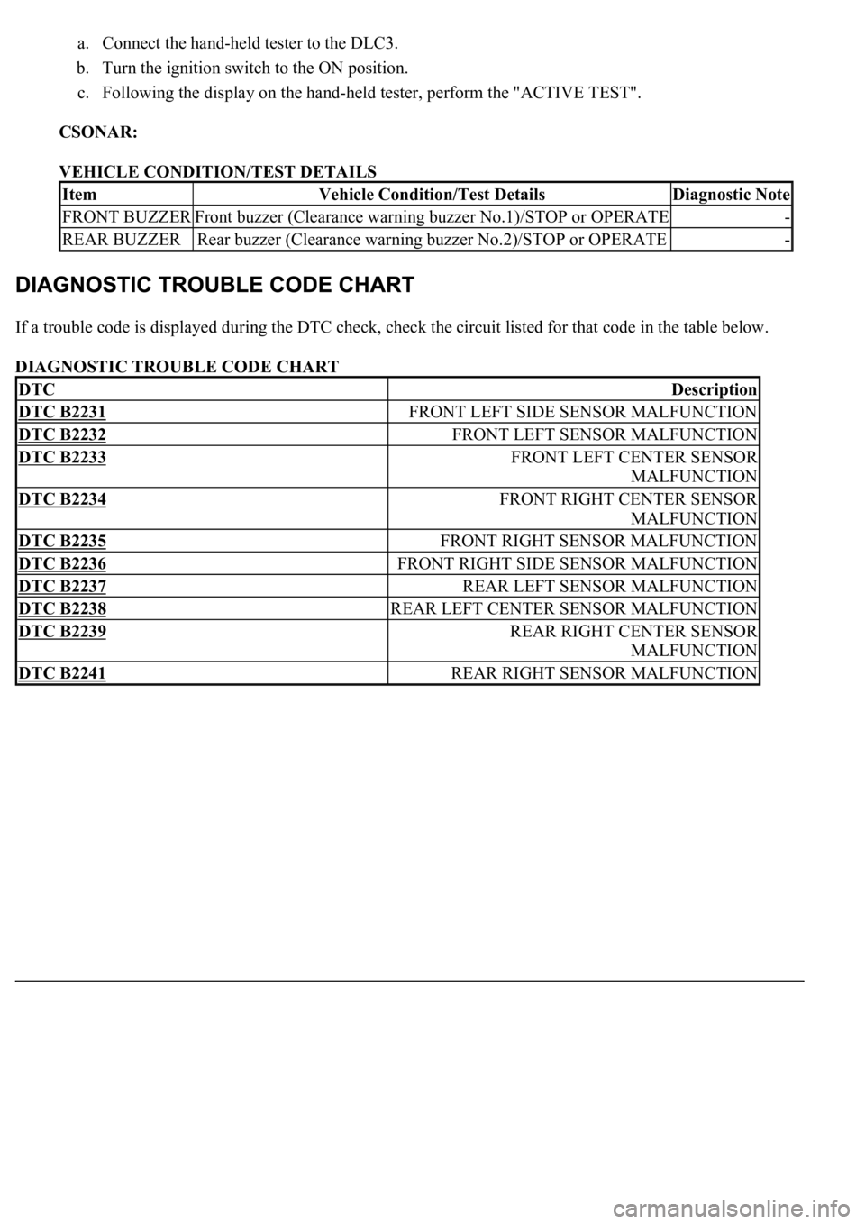
a. Connect the hand-held tester to the DLC3.
b. Turn the ignition switch to the ON position.
c. Following the display on the hand-held tester, perform the "ACTIVE TEST".
CSONAR:
VEHICLE CONDITION/TEST DETAILS
If a trouble code is displayed during the DTC check, check the circuit listed for that code in the table below.
DIAGNOSTIC TROUBLE CODE CHART
ItemVehicle Condition/Test DetailsDiagnostic Note
FRONT BUZZERFront buzzer (Clearance warning buzzer No.1)/STOP or OPERATE-
REAR BUZZERRear buzzer (Clearance warning buzzer No.2)/STOP or OPERATE-
DTCDescription
DTC B2231FRONT LEFT SIDE SENSOR MALFUNCTION
DTC B2232FRONT LEFT SENSOR MALFUNCTION
DTC B2233FRONT LEFT CENTER SENSOR
MALFUNCTION
DTC B2234FRONT RIGHT CENTER SENSOR
MALFUNCTION
DTC B2235FRONT RIGHT SENSOR MALFUNCTION
DTC B2236FRONT RIGHT SIDE SENSOR MALFUNCTION
DTC B2237REAR LEFT SENSOR MALFUNCTION
DTC B2238REAR LEFT CENTER SENSOR MALFUNCTION
DTC B2239REAR RIGHT CENTER SENSOR
MALFUNCTION
DTC B2241REAR RIGHT SENSOR MALFUNCTION
Page 1528 of 4500
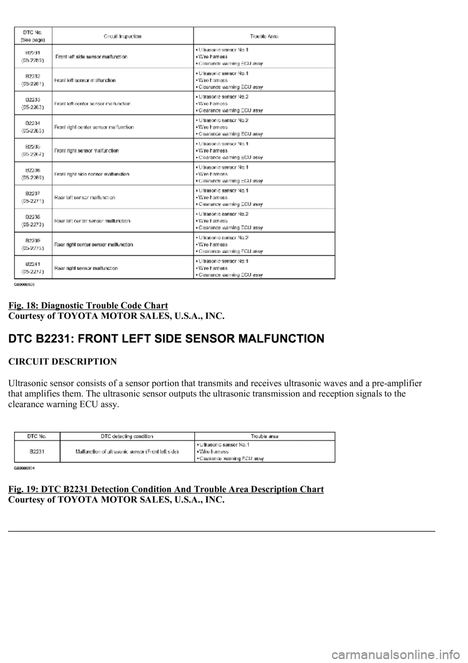
Fig. 18: Diagnostic Trouble Code Chart
Courtesy of TOYOTA MOTOR SALES, U.S.A., INC.
CIRCUIT DESCRIPTION
Ultrasonic sensor consists of a sensor portion that transmits and receives ultrasonic waves and a pre-amplifier
that amplifies them. The ultrasonic sensor outputs the ultrasonic transmission and reception signals to the
clearance warning ECU assy.
Fig. 19: DTC B2231 Detection Condition And Trouble Area Description Chart
Courtesy of TOYOTA MOTOR SALES, U.S.A., INC.
Page 1529 of 4500
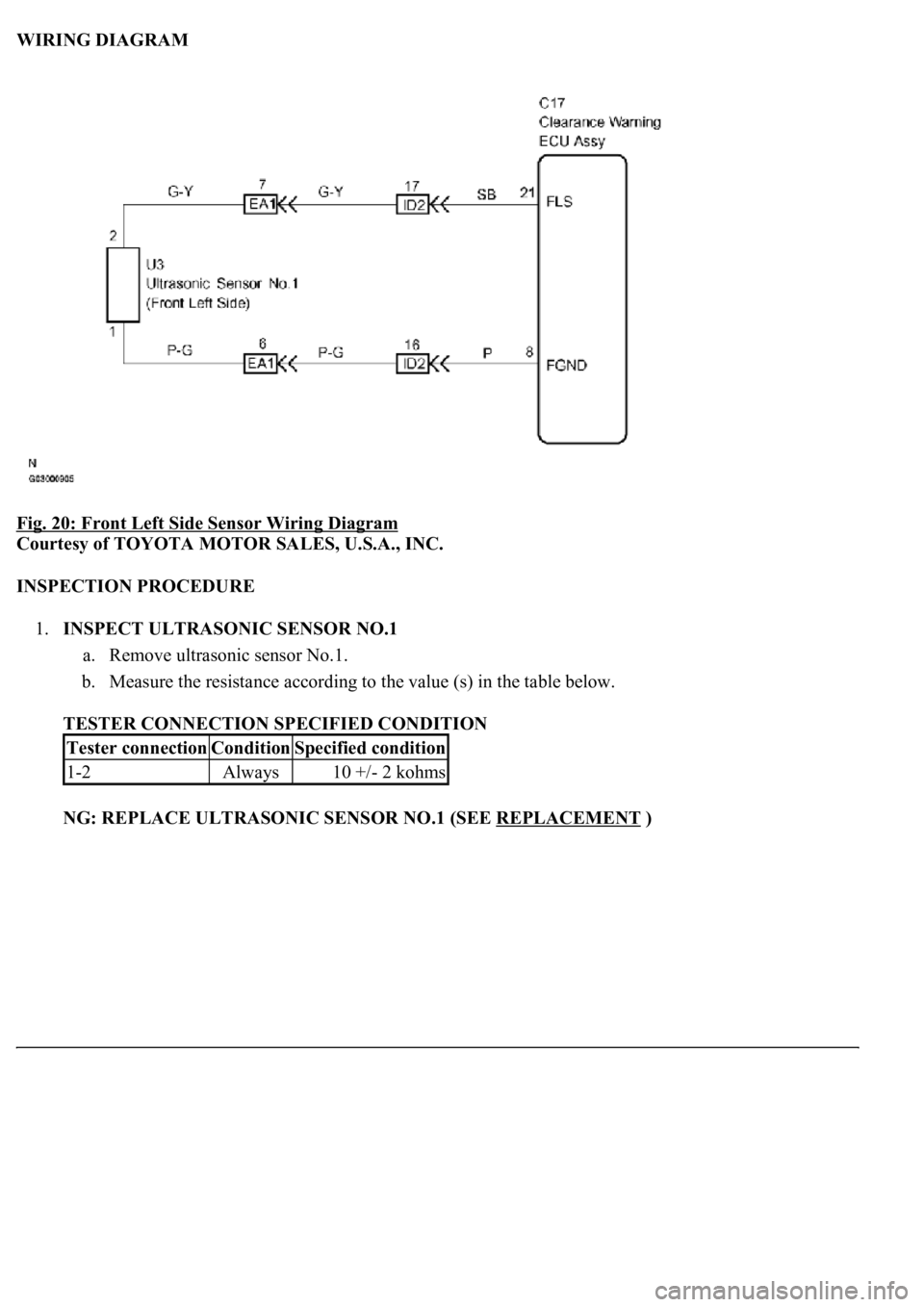
WIRING DIAGRAM
Fig. 20: Front Left Side Sensor Wiring Diagram
Courtesy of TOYOTA MOTOR SALES, U.S.A., INC.
INSPECTION PROCEDURE
1.INSPECT ULTRASONIC SENSOR NO.1
a. Remove ultrasonic sensor No.1.
b. Measure the resistance according to the value (s) in the table below.
TESTER CONNECTION SPECIFIED CONDITION
NG: REPLACE ULTRASONIC SENSOR NO.1 (SEE REPLACEMENT
)
Tester connectionConditionSpecified condition
1-2Always10 +/- 2 kohms
Page 1530 of 4500
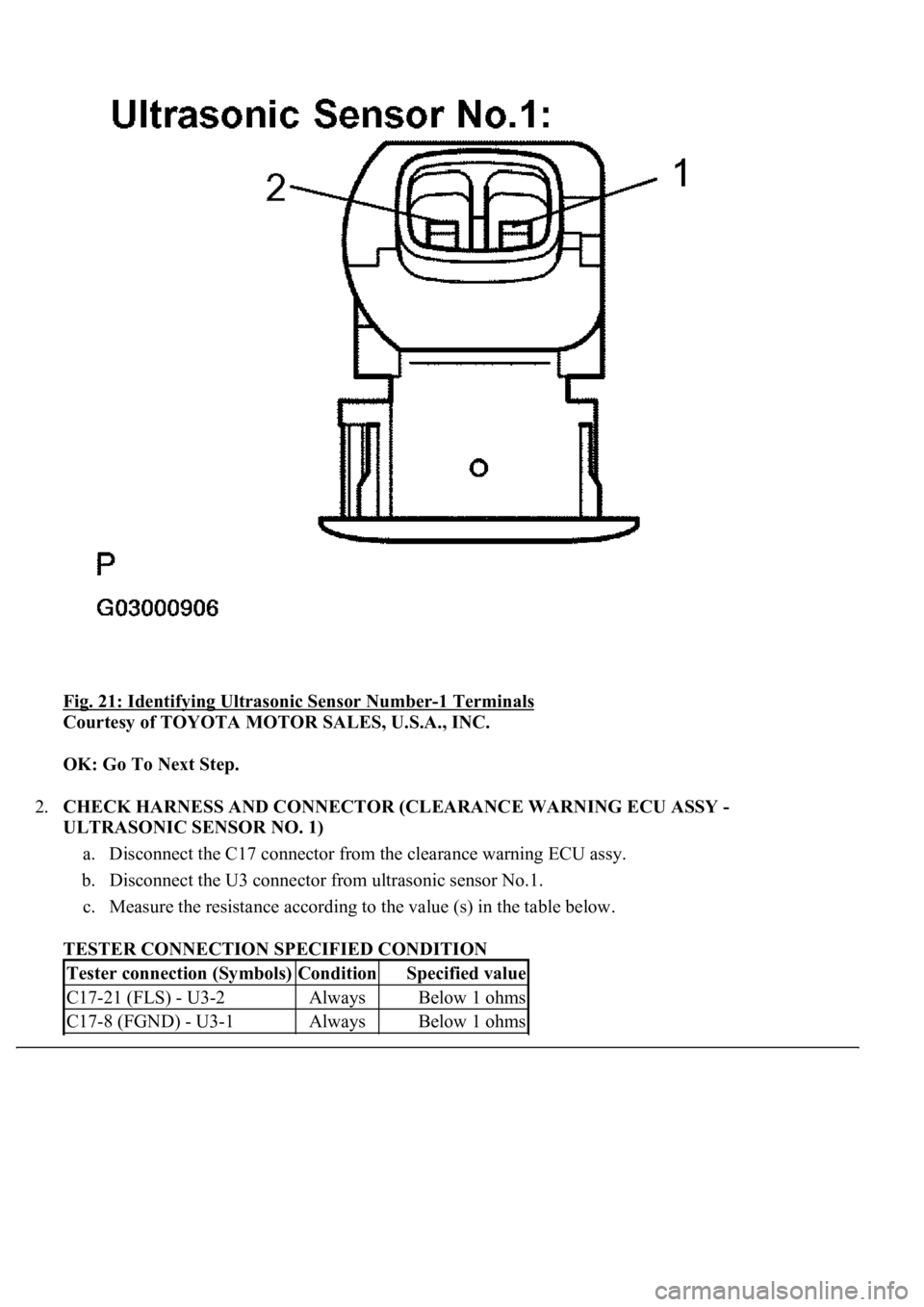
Fig. 21: Identifying Ultrasonic Sensor Number-1 Terminals
Courtesy of TOYOTA MOTOR SALES, U.S.A., INC.
OK: Go To Next Step.
2.CHECK HARNESS AND CONNECTOR (CLEARANCE WARNING ECU ASSY -
ULTRASONIC SENSOR NO. 1)
a. Disconnect the C17 connector from the clearance warning ECU assy.
b. Disconnect the U3 connector from ultrasonic sensor No.1.
c. Measure the resistance according to the value (s) in the table below.
TESTER CONNECTION SPECIFIED CONDITION
Tester connection (Symbols)ConditionSpecified value
C17-21 (FLS) - U3-2AlwaysBelow 1 ohms
C17-8 (FGND) - U3-1AlwaysBelow 1 ohms